1
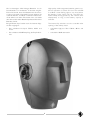
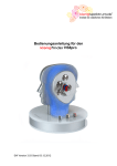
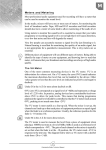
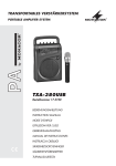
Betriebsanleitung
Operating Instructions
Ollenhauerstr. 98
13403 Berlin
Germany
Tel.: +49-30 / 417724-0
Fax: +49-30 / 417724-50
Email: [email protected]
Web: www.neumann.com
KU 100
Inhaltsverzeichnis
Table of Contents
1.
Kurzbeschreibung
1.
Overview
2.
Der Kunstkopf KU 100
2.
The KU 100 Dummy Head
2.1
Wirkungsweise und Anwendung
2.1
Principles of Operation and Applications
2.2
Die Mikrophonausgänge
2.2
Microphone Outputs
2.2.1 Der symmetrische Ausgang
2.1.1 Balanced Output
2.2.2 Die unsymmetrischen Ausgänge
2.2.2 Unbalanced Outputs
2.3
Das Öffnen des Kunstkopfes
2.3
The Opening of the Dummy Head
2.4
Das schaltbare Hochpaßfilter,
der –10 dB-Schalter
2.4
Switchable High-Pass Filter,
–10 dB Switch
2.5
Mikrophonkabel
2.5
Microphone Cables
3.
Stromversorgung
3.
Power Supply
3.1
Batteriespeisung
3.1
Battery Operation
3.2
Betrieb mit externem Netzgerät
3.2
Operation with External Power Supply Unit
3.3
Phantomspeisung
3.3
Phantom Powering
4.
Frequenzgänge
4.
Frequency Responses
4.1
Freifeldfrequenzgang
4.1
Free-field Frequency Response
4.2
Diffusfeldfrequenzgang
4.2
Diffuse-field Frequency Responses
4.3
Terzpegel der Eigenstörspannung
4.3
Third-Octave Self Noise Level
5.
Technische Daten KU 100
5.
KU 100 Technical Specifications
6.
Das Kalibrieren der Kunstkopfsysteme
6.
Calibrating the Dummy Head Systems
7.
Servicehinweise
7.
Service
8.
Zubehör
8.
Accessories
2
1. Kurzbeschreibung
1. Overview
Der Kunstkopf KU 100 ist in seinen Abmessungen
dem menschlichen Kopf nachgebildet und in den
Ohren mit Mikrophonen ausgerüstet.
The KU 100 dummy head is a replication of the
human head, equipped with microphones within the
“ears”. Listening to recordings made with this system through high-quality, diffuse-field equalized headphones or analyzing the acoustic data gathered by
the system affords a “listening” impression which
dimensionally recreates the acoustical information
present at the location of the head during the original
acoustical “event” (i.e. ‘Head-Related Stereophony’).
Zum Abhören der Kunstkopfsignale sollten hochwertige, diffusfeldentzerrte Kopfhörer verwendet
werden. Dann gewinnt man den Eindruck des Dabeiseins am Ort der Darbietung („Kopfbezogene
Stereophonie“).
Das Klangbild bei Lautsprecherwiedergabe entspricht
weitgehend dem eines herkömmlichen Stereomikrophons, jedoch mit differenzierterer Abbildung der
Raumtiefe.
lf reproduced through loudspeakers, the sound impressions are almost identical to those obtained by
means of conventional stereo microphone techniques
with an increased sense of “depth” of the soundstage.
Aufgrund seiner Bauweise eignet sich der Kunstkopf
als Aufnahmesystem und Meßmittel vor allem für
folgende Aufgaben:
Thanks to its design, the dummy head is a suitable
means of recording and monitoring for a number of
applications, in particular:
•
Hörspiel/Featureproduktionen
•
Radio Drama/Feature Productions
•
Konzertmitschnitte und Live-Übertragungen aus
den Bereichen Klassik, Jazz, Pop und Unterhaltung
•
Recording of concerts and live broadcasts in
the areas of classical music, jazz, pop music, and
entertainment shows
•
Stereoaufnahmen ohne großen Aufwand in akustisch sehr komplexen Räumen – z. B. in Kirchen
•
Stereo recordings with relatively simple means
in acoustically very complex environments (i.e.
churches, etc.)
•
Dokumentation von Tierstimmen und Naturbildern, von Konferenzen, Theater- und Opernaufführungen
•
Documentation of animal voices and natural
sounds, conferences, theater and opera performances
•
Einspielkontrolle in Sälen, Theatern und Auditorien
•
Monitoring of the effect of P.A. Systems in halls,
theaters, and auditoriums
•
Dokumentation und Beurteilung der Hörsamkeit
von Räumen wie z. B. Konzertsälen
•
Documentation and assessment of the audibility
conditions of rooms (i.e. concert halls)
•
Dokumentation und Beurteilung von Musikinstrumenten
•
Documentation and assessment of musical instruments
•
Dokumentation und Beurteilung einer elektroakustischen Übertragungsanlage in Räumen oder auch
in Fahrzeugen (Kommunikationsanlagen, Autolautsprecher)
•
Documentation and assessment of electroacoustic
P.A. Systems in rooms and/or in automobiles
(i.e. evaluation of automotive loudspeakers)
•
Sprachverständlichkeitsmessungen
•
Measurement of speech intelligibility
•
Dokumentation und Beurteilung der Belästigung
durch Lärm in der Industrie, am Arbeitsplatz und
im Verkehr
•
Documentation and assessment of noise nuisance
in industry, at workplaces or in traffic
•
Messung von (offenen) Kopfhörern
•
Measurement of (open) headphones
The dummy head is provided with balanced and
unbalanced, transformerless outputs.
Der Kunstkopf besitzt symmetrische und unsymmetrische transformatorlose Ausgänge.
3
Der symmetrische Ausgang
Balanced output
5-poliger XLR-Stecker:
5-pin XLR connector, pin assignment:
0 V, Masse
Pin 1:
0 V, ground
Stift 2 (+):
Stift 3:
Modulation linker Kanal
Pin 2 (+):
Pin 3:
modulation left channel
Stift 4 (+):
Stift 5:
Modulation rechter Kanal
Pin 4 (+):
Pin 5:
modulation right channel
Stift 1:
Über diesen symmetrischen Ausgang kann der Kunstkopf
KU 100 mit 48 V, 3,5 mA pro Kanal phantomgespeist
werden (DIN EN 60268-12 bzw. IEC 60268-12). Es
müssen stets beide Kanäle gespeist werden.
This balanced output also permits phantom powering of the KU 100 dummy head with dual 48 V,
3.5 mA (DIN EN 60268-12 and/or IEC 60268-12).
Both channels always have to be powered.
Der Anschluß erfolgt über das beigelegte 5-adrige
Kabel IC 5, das mit Hilfe des ebenfalls mitgelieferten
Adapterkabels AC 20 auf zwei 3-polige XLR-Stecker
aufgelöst werden kann.
The KU 100 dummy head is connected by means of
the 5-pin IC 5 cable (supplied) which can be distributed to two 3-pin XLR connectors by means of the
AC 20 adapter cable (supplied as well).
Kabelfarbe gelb: linker Kanal, Kabelfarbe rot: rechter
Kanal.
Yellow cable: left channel, red cable: right channel.
Steckerbelegung:
Connector pin assignment:
Stift 1:
0 V, Masse
Pin 1:
0 V, ground
Stift 2 (+):
Stift 3:
Modulation für symmetrische Eingänge
Pin 2 (+):
Pin 3:
modulation for balanced inputs
Der unsymmetrische Ausgang
Unbalanced output
BNC-Buchse L für den linken Kanal und BNC-Buchse R für den rechten Kanal.
Female BNC connector L for left channel and BNC
connector R for right channel.
Bei Verwendung dieser Ausgänge wird der Kunstkopf
KU 100 entweder intern mit Batterien oder extern
mit dem beiliegenden Steckernetzteil gespeist.
When these outputs are used the KU 100 dummy
head is powered either via internal batteries or via
the external power supply unit.
Stromversorgung
Power Supply
Wahl der Stromversorgung mit dem Kippschalter
neben dem 5-poligen XLR-Ausgang:
Power supply adjustment by means of the flip switch
beside the 5-pin XLR output:
„P48“ für Phantomspeisung über den symmetrischen
Ausgang des Kunstkopfes
“P48” for phantom powering via the balanced output
of the dummy head
„BATT.“ für Speisung durch 6 Batterien LR 6, Größe AA im Kunstkopf
“BATT.” for powering via six LR 6 batteries, size AA,
within the dummy head
„EXT.“ für Speisung über das mitgelieferte Steckernetzteil, anzuschließen an dem 2-poligen Einbaustekker „EXT.“
“EXT.” for powering via the power supply unit supplied, to be connected to the 2-pin male connector
“EXT. ”
Etwa 10 s nach dem Anschalten ist der Kunstkopf
betriebsbereit.
The dummy head is ready for operation approx.
10 seconds after power-up.
Zum Einlegen der Batterien den Kunstkopf mit den
beiden Vierteldrehverschlüssen am Hinterkopf entriegeln und auseinanderziehen. Dann wird ein Batteriegehäuse für sechs Batterien des Typs LR 6,
Größe AA („Mignon“) zugänglich.
In order to install the batteries, unlock the dummy
head at the two 90° lock fasteners at the back of the
head, and pull the two halves apart. The battery box
for six batteries, type LR 6, size AA (round cells) is
then accessible.
(+) positiver Spannungsanstieg bei einem Schalldruckanstieg vor dem jeweiligen Ohr
(+) polarity at a sudden rise of sound pressure in front of the respective
ear
4
Mit hochwertigen Alkali-Mangan-Batterien ist ein
Dauerbetrieb von mindestens 15 Stunden möglich.
Etwa eine Stunde, bevor die Batterien die Stromversorgung nicht mehr sicherstellen können, beginnt die
rote Leuchtdiode „Low Batt.“ zu blinken. Die Leuchtdiode blinkt auch beim Einschalten kurz auf, bleibt
aber bei ausreichender Batteriekapazität während des
Betriebs dunkel.
High-quality alkali-manganese batteries permit continuous operation of at least 15 hours. The red LED
“Low Batt.” starts flashing approx. one hour before
the battery power supply will fail. The LED also
flashes briefly during power-up, but remains dark
subsequently as long as the battery capacity is
sufficient.
Bei geöffnetem Kopf werden auch die internen Kippschalter zugänglich:
The internal flip switches are also accessible after
opening of the dummy head:
•
Der schaltbare Hochpaß 150 Hz, 40 Hz und
Linear
•
switchable high-pass filter 150 Hz, 40 Hz, and
linear
•
Die schaltbare 10 dB-Dämpfung der Empfindlichkeit
•
switchable 10 dB attenuation
5
2. Der Kunstkopf KU 100
2. KU 100 Dummy Head
2.1 Wirkungsweise und Anwendung
2.1 Principles of Operation and
Applications
Der Kunstkopf KU 100 ist in seinen Abmessungen
dem menschlichen Kopf nachgebildet und anstelle
der beiden Gehörorgane mit Mikrophonen ausgerüstet. Beim Abhören des Kunstkopfsignals mit einem
hochwertigen, diffusfeldentzerrten Kopfhörer entsteht
ein Höreindruck, der fast vollständig demjenigen
gleicht, den der Hörer bei stillgehaltenem Kopf am
Ort des Kunstkopfes gewinnen würde und vermittelt
daher die Illusion des Dabeiseins am Ort der Darbietung.
The KU 100 dummy head is a replica dimensionwise
of the human head, equipped with microphones in
place of the ears. Listening to the dummy head
signals through high-quality, diffuse-field equalized
headphones, the listener receives an impression
which is almost completely identical to that which he
or she would have when keeping the head stationary at the location of the dummy head, i.e. the
illusion of physical presence at the scene of the performance.
Das Klangbild bei Lautsprecherwiedergabe entspricht
weitgehend dem, das ein herkömmliches Stereomikrophon am Ort des Kunstkopfes übertragen
würde, jedoch mit differenzierterer Abbildung der
Raumtiefe.
lf reproduced through loudspeakers, the sound impressions are almost identical to those obtained by
means of conventional stereo microphone techniques
with an increased sense of “depth” of the soundstage.
Für kreative Hörspielgestaltung ist der Kunstkopf
ebenso gut geeignet wie beispielweise für Musikaufnahmen, wobei der Vorteil gegenüber herkömmlicher
Aufnahmetechnik in der getreuen Übertragung der
Raumakustik liegt. Der KU 100 wird aber auch zur
Untersuchung von Lärmeinflüssen an verschiedensten Arbeitsplätzen unter wirklichkeitsgetreuen Bedingungen eingesetzt. Dabei wird das Schallfeld physiologisch richtig erfaßt, kann aufgezeichnet und bei
Bedarf erst später – evtl. von mehreren Versuchspersonen unter denselben Hörbedingungen – ausgewertet werden.
For artistic recordings, the KU 100 is equally suited
for creative radio drama recordings and for music
presentations, the advantage of the KU 100 over conventional stereo recording techniques being a more
realistic representation of the acoustic conditions in
the recording environment. In industrial applications,
the KU 100 can be utilized to assess noise influences
at different workplaces under realistic conditions.
The sound field is received in a physiologically proper
manner and can be recorded for subsequent evaluation by different test subjects under the same
listening conditions.
Der KU 100 stellt bereits die dritte Generation des
Neumann-Kunstkopfes dar. Während der Schritt vom
ersten Studio-Kunstkopf, dem KU 80, zum KU 81 der
Übergang von der Freifeldentzerrung zur Diffusfeldentzerrung war und damit die Lautsprecherkompatibilität der Kunstkopfsignale sicherstellte, werden im
Kunstkopf KU 100 folgende technische Verbesserungen angeboten:
The KU 100 represents the third generation of the
Neumann artificial head stereo microphone systems
(dummy head). The original KU 80 was replaced by
the KU 81 which marked the transition from “freefield” equalization to “diffuse-field” equalization. This
yielded compatibility of the dummy head signals with
stereo loudspeaker reproduction. The KU 100 replaces the KU 81 and offers the following advancements:
Akustische Verbesserungen
Acoustic lmprovements
•
Überarbeitung der Außenohren für exakte
Symmetrie der Charakteristika links/rechts
•
Revised design of the outer ears for precise
symmetry of the left/right characteristics
•
noch bessere Annäherung an das Ideal „ebener
Diffusfeldfrequenzgang“
•
Improved approximation of the ideal “smooth
diffuse-field frequency response”
•
Korrektur der Ohrkoordinaten zur Vermeidung
einer Elevation der Schallquellen im Hörereignis
•
Adjusted ear coordinates, thereby avoiding
vertical displacements of sound sources (artificial
elevations) in the listening event
6
Schaltungstechnische Verbesserungen
Improved Circuitry
•
Transformatorlose Schaltungstechnik „fet 100“
•
Transformerless “fet 100” circuit
•
Erhöhung des Übertragungsmaßes um 5 dB
•
Sensitivity increased by 5 dB
•
Erweiterung des Dynamikumfangs um 5 dB
•
Dynamic range increased by 5 dB
Verbesserte Handhabung
Improved Flexibility
•
•
•
Mehrfache Stromversorgungsmöglichkeit:
Flexible power supply configurations:
–
Eingebaute Batteriespeisung mit KontrollLED „Low Batt.“
–
Integrated battery supply with LED “low
battery power”
–
externe Phantomspeisung P48 durch 5-poligen XLR-Stecker
–
external P48 phantom powering via 5-pin
XLR connection
–
Versorgung aus mitgeliefertem Steckernetzgerät möglich
–
powering via supplied external power
supply unit
Alternative Ausgangsbeschaltung:
–
•
Symmetrische XLR-Ausgänge für Studiobetrieb und getrennte links/rechts BNC-Ausgänge für unsymmetrische Meß-, Daten-und
Speichergeräte eingebaut
Flexible output connector configurations:
–
Integrated, balanced XLR outputs for studiooperation as well as separate Left/Right
BNC outputs for unbalanced measuring,
data processing and data storage devices
•
Schaltbares Hochpaßfilter (150 Hz, 40 Hz und
Linear)
•
Switchable high-pass filter (150 Hz, 40 Hz and
linear)
•
Schaltbare 10 dB-Dämpfung
•
Switchable 10 dB attenuation
Gerade wegen der aufgeführten Verbesserungen
haben die grundsätzlichen Veröffentlichungen über
das Arbeiten mit dem Kunstkopf, die in der beiliegenden Dokumentation zusammengestellt sind,
weiterhin Gültigkeit.
Especially because of the above-mentioned improvements, the general publications concerning the use
of the dummy head, which are compiled in the enclosed documentation, remain in full effect.
Sie sollen zeigen, wo der Kunstkopf als Aufnahmesystem und Meßmittel bisher mit Erfolg eingesetzt
wurde und warum er sich für die im folgenden aufgeführten Aufgaben z.T. besser eignet als „normale“ Stereomikrophonanordnungen oder Meßmikrophone:
Their purpose is to describe applications in which the
dummy head as a recording system and measuring
instrument has been successfully used so far, and
why it is sometimes more suitable than “normal”
stereo microphone arrangements or measuring microphones for the applications described below:
•
Hörspiel/Featureproduktionen
•
Radio Drama/Feature Productions
•
Konzertmitschnitte und Live-Ubertragungen aus
den Bereichen Klassik, Jazz, Pop und Unterhaltung
•
Recording of concerts and live broadcasts in the
areas of classical music, jazz, pop music, and
entertainment shows
•
Stereoaufnahmen ohne großen Aufwand in akustisch sehr komplexen Räumen – z.B. in Kirchen
•
Stereo recordings with relatively simple means
in acoustically very complex environments (i.e.
churches, etc.)
•
Dokumentation von Tierstimmen und Naturbildern, von Konferenzen, Theater- und Opernaufführungen
•
Documentation of animal voices and natural
sounds, conferences, theater and opera performances
•
Einspielkontrolle in Sälen, Theatern und Auditorien
•
Monitoring of the effect of P.A. Systems in halls,
theaters, and auditoriums
7
•
Dokumentation und Beurteilung der Hörsamkeit
von Räumen wie z.B. KonzertsäIen
•
Documentation and assessment of the audibility
conditions of rooms (i.e. concert halls)
•
Dokumentation und Beurteilung von Musikinstrumenten
•
Documentation and assessment of musical instruments
•
Dokumentation und Beurteilung einer elektroakustischen Übertragungsanlage in Räumen oder auch
in Fahrzeugen (Kommunikationsanlagen, Autolautsprecher)
•
Documentation and assessment of electroacoustic
P.A. Systems in rooms and/or in automobiles
(i.e. evaluation of automotive loudspeakers)
•
Sprachverständlichkeitsmessungen
•
Measurement of speech intelligibility
•
Dokumentation und Beurteilung der Belästigung
durch Lärm in der Industrie, am Arbeitsplatz und
im Verkehr
•
Documentation and assessment of noise nuisance
in industry, at workplaces or in traffic
•
Messung von (offenen) Kopfhörern
•
Measurement of (open) headphones
Der Kunstkopf ist das Anfangsglied einer Übertragungskette in „Kopfbezogener Stereophonie“. Am
anderen Ende sollten hochwertige diffusfeldentzerrte
Kopfhörer stehen. Deshalb wird in der beiliegenden
Literaturauswahl auch auf die optimale Kopfhörerentzerrung bzw. auf entsprechend konstruierte Kopfhörer eingegangen.
The dummy head is the first link of the transmission
chain in “Head-Related Stereophony”. High-quality,
diffuse-field equalized headphones should be on the
other end. This is why the enclosed literature also
refers to the subject of optimal headphone equalization as well as suitable designed headphones.
2.2 Die Mikrophonausgänge
2.2 Microphone Outputs
Der Kunstkopf KU 100 besitzt symmetrische und
unsymmetrische transformatorlose Ausgänge.
The KU 100 dummy head is provided with balanced
and unbalanced, transformerless outputs.
2.2.1
2.2.1 Balanced Output
Der symmetrische Ausgang
The balanced 5-pin XLR output features the following circuitry according to DIN EN 60268-12 and/or
IEC 60268-12:
Der symmetrische 5-polige XLR-Ausgang hat folgende Beschaltung gemäß DIN EN 60268-12 bzw. IEC
60268-12:
0 V, Masse
Pin 1:
0 V, ground
Stift 2 (+):
Stift 3:
Modulation linker Kanal
Pin 2 (+):
Pin 3:
modulation left channel
Stift 4 (+):
Stift 5:
Modulation rechter Kanal
Pin 4 (+):
Pin 5:
modulation right channel
Stift 1:
Über diesen symmetrischen Ausgang kann der Kunstkopf KU 100 mit 48 V, 3,5 mA pro Kanal phantomgespeist werden (s. Kapitel 3.3 „Phantomspeisung“).
This balanced output also permits phantom powering of the KU 100 dummy head with 48 V, 3.5 mA,
each channel, (see chapter 3.3: “Phantom, powering”).
Es muß beachtet werden, daß an diesem Ausgang auch bei Speisung aus Batterien oder aus
dem externen Steckernetzgerät die 48 V-Phantomspeisung anliegt, die intern erzeugt wird.
Note that the 48 V phantom power, which is
generated internally, is present at the output
even if power is obtained via the internal batteries or via the external power supply unit.
(+) positiver Spannungsanstieg bei einem Schalldruckanstieg vor dem jeweiligen Ohr
(+) polarity at a sudden rise of sound pressure in front of the respective
ear
8
Daher müssen spezielle Kabel verwendet werden,
falls der XLR-Ausgang für unsymmetrische Eingänge
benutzt werden soll (s. Kapitel 2.5 „ Mikrophonkabel“).
Special cables are hence necessary if the XLR output
has to be used for unbalanced inputs (see chapter
2.5: “Microphone cable”).
Der 5-polige XLR-Ausgang kann mit Hilfe des
zum Lieferumfang gehörigen Adapterkabels AC 20
auf zwei 3-polige XLR-Stecker aufgelöst werden
und paßt dann auf in der Studiotechnik übliche
(phantomgespeiste) Mikrophoneingänge (s. Kapitel
2.5 „Mikrophonkabel“).
The 5-pin XLR output can be distributed to two
3-pin XLR connectors by means of the AC 20
adapter cable supplied and then matches the
common (phantom-powered) microphone inputs for
studio applications (see chapter 2.5: “Microphone
cable”).
2.2.2
2.2.2 Unbalanced Outputs
Die unsymmetrischen Ausgänge
Für den Betrieb an unsymmetrischen Eingängen
(DAT-Recorder, Meßgeräte etc.) stehen die Ausgangssignale gleichspannungsfrei an zwei BNC-Buchsen, beschriftet mit L für den linken Kanal und R für
den rechten Kanal, zur Verfügung.
The output signals are also available dc-free at two
female BNC connectors (marked “L” and “R” for left
and right respectively) for operation in conjunction
with unbalanced inputs, (i.e. DAT recorders, measurement instruments, etc.).
Bei Verwendung dieser Ausgänge wird der KU 100
entweder intern mit Batterien oder extern mit
dem beiliegenden Steckernetzteil gespeist. Siehe
dazu Kapitel 2.3 „Das Öffnen des Kunstkopfes“, Kapitel 3.1 „Batteriespeisung“ und Kapitel 3.2 „Betrieb
mit externem Netzgerät.
When the engineer is utilizing the unbalanced outputs, the required phantom power can be obtained
either via internal batteries or via the external power
supply. See chapter 2.3: “Opening the dummy head”,
chapter 3.1: “Battery supply”, and chapter 3.2: “Operation with external power supply unit“.
Durch spezielle Adapterkabel (separat lieferbares
Zubehör) kann der Kunstkopf auch unter Verwendung
des 5-poligen XLR-Ausgangs auf unsymmetrische
Klinkeneingänge geschaltet werden. Siehe Kapitel 2.5
„Mikrophonkabel“.
By means of special adapter cables (separately available accessories) the dummy head can also be connected to unbalanced jack-plug inputs. See chapter
2.5: “Microphone Cables”.
2.3 Das Öffnen des Kunstkopfes
2.3 Opening the Dummy Head
Zum Einlegen bzw. Austauschen von Batterien bei
netzunabhängiger Speisung, zum Bedienen des
schaltbaren Hochpaßfilters oder der 10 dB-Dämpfung
oder für eventuelle Reparaturarbeiten muß der Kunstkopf geöffnet werden.
The KU 100 dummy head can be opened to access
the batteries for mains-independent power supply, to
operate the switchable high-pass filter or the 10 dB
attenuation unit, or whenever any service work has
to be done.
Dieses geschieht mit Hilfe der beiden Vierteldrehverschlüsse am Hinterkopf. Sie werden durch jeweils
eine Viertel-Linksdrehung entriegelt. Dann kann die
hintere Kopfhälfte (ohne Ohren) parallel nach hinten
abgezogen werden, während die vordere Kopfhälfte
z.B. auf dem Stativ etc. verbleiben kann.
This is done by means of the two 90° lock fasteners at the back of the head which are unlocked by
turning them counter-clockwise. The back of the
head (without the ears) can then be pulled off leaving
the front which can be left in place, e.g. on a microphone stand.
Nach dem Öffnen des Kunstkopfes werden die Batteriehalterung, die Ohrsysteme und das Gehäuse der
Ausgangsstufe sichtbar.
The battery holder, the ear systems, and the output
stage are visible after opening the dummy head.
Der Zusammenbau erfolgt sinngemäß umgekehrt
durch Aufschieben des Hinterkopfes mit anschließendem Verriegeln durch Rechtsdrehung der beiden
Vierteldrehverschlüsse, bis die Knäufe waagerecht
positioniert sind.
For reassembly, proceed in inverse order: first fix the
back of the head in place and lock by turning the lock
fasteners until the knobs are in a horizontal position.
9
2.4 Das schaltbare Hochpaßfilter,
der –10 dB-Schalter
2.4 Switchable High-Pass Filter,
–10 dB Switch
Nach dem Öffnen des Kunstkopfes (s. Kapitel 2.3)
werden an der Oberseite der Ausgangsstufe zwei
Kippschalter zugänglich:
After opening the dummy head, (see chapter 2.3)
two flip switches are accessible on top of the output stage:
Links der 3-stufige Schalter für verschiedene Grenzfrequenzen eines Hochpaßfilters, rechts der –10 dBSchalter zur Reduzierung des Übertragungsmaßes.
On the left-hand side is a 3-position switch for
different corner frequencies of a high-pass filter. The
–10 dB pad switch is on the right.
Beide Schalter wirken jeweils auf beide Kanäle.
Each switch influences both channels.
Die –3 dB-Grenzfrequenzen des Hochpaßfilters sind:
The –3 dB corner frequencies of the high-pass filter
are:
8 Hz in Schalterstellung LIN, 40 Hz und 150 Hz. Dadurch lassen sich tieffrequente Störungen wie z.B.
Körperschall ausblenden.
8 Hz in the LIN position, 40 Hz, and 150 Hz. This
feature permits elimination of low-frequency interferences, such as structure-borne noise.
2.5 Mikrophonkabel
2.5 Microphone Cable
Der symmetrische Anschluß des Kunstkopfes
KU 100 erfolgt über das beigelegte 5-polige geschirmte Mikrophonkabel IC 5.
Balanced connection to the KU 100 dummy head is
possible via the shielded, 5-conductor microphone
cable IC 5 (supplied).
Mit Hilfe des ebenfalls zum Lieferumfang gehörenden Adapterkabels AC 20 kann die 5-polige XLRArmatur auf zwei 3-polige XLR-Stecker aufgelöst
werden und paßt dann auf in der Studiotechnik übliche (phantomgespeiste) Mikrophoneingänge.
The 5-pin XLR fitting can be distributed to two
3-pin XLR connectors by means of the AC 20
adapter cable (supplied) and then matches the common (phantom-powered) microphone inputs for
studio applications.
Die Kabelfarbe gelb des Adapterkabels AC 20 bezeichnet den linken Kanal, die Farbe rot den rechten
Kanal.
The yellow cable of the AC 20 adapter cable is for
the left channel, the red cable for the right channel.
Die 3-poligen Stecker XLR 3 M sind entsprechend
DIN EN 60268-12 bzw. IEC 60268-12 beschaltet:
The 3-pin XLR 3 male connectors are wired according to DIN EN 60268-12 and/or IEC 60268-12:
Jeweils
Stift 1:
0 V, Gehäuse (Masse)
Pin 1:
0 V, shield (ground)
Stift 2 (+):
Stift 3:
Modulation für symmetrische
Eingänge
Pin 2 (+):
Pin 3:
modulation for balanced inputs
Als separates Zubehör ist das Adapterkabel AC 29
lieferbar. Mit ihm kann der 5-polige XLR-Stecker des
Kunstkopfes auf unsymmetrische Eingänge von z.B.
DAT-Recordern adaptiert werden.
The AC 29 adapter cable is available as separate accessory. It facilitates connection of the 5-pin XLR
connector of the dummy head to unbalanced inputs,
e.g. of DAT recoders.
Das Kabel AC 29 führt die Modulation auf zwei
6,3 mm Ø Monoklinkenstecker. Das Kabel hat RCGlieder eingebaut, um die am 5-poligen XLR-Ausgang des KU 100 anstehende Gleichspannung abzublocken.
The AC 29 cable routes the modulation to two
mono 1/4" type jack-plug connectors, 6.3 mm. The
cable is provided with integrated RC elements in order to ward off the dc voltage which is available at
the 5-pin XLR output of the KU 100.
(+) positiver Spannungsanstieg bei einem Schalldruckanstieg vor dem jeweiligen Ohr
(+) polarity at a sudden rise of sound pressure in front of the respective
ear
10
Eine Verlängerung des 5-poligen Kabels ist mit
weiteren Kabeln vom Typ IC 5 (separates Zubehör)
möglich. Standardlänge ist jeweils 10 m.
The 5-pin cable can be extended by means of
additional cables, type IC 5 (separate accessories).
The standard length is 10 meters.
Die 3-poligen XLR-Stecker des AC 20 können mit
zwei 10 m langen Kabeln IC 3 (3-polig XLR, separates Zubehör) verlängert werden.
The 3-pin XLR connectors of the AC 20 can be extended by means of two 10 meter IC 3 cables
(3-pin XLR, separate accessories).
Andere Kabellängen und/oder Kabelmaterial ohne
Armaturen sind auf Wunsch lieferbar.
Cables of different length and/or cables without
fittings are available on request.
Die akustischen Eigenschaften des Kunstkopfes werden auch durch sehr lange (Neumann-)Kabel nicht
beeinflußt. Erst bei einer Kabellänge deutlich über
300 m macht sich ein Abfall im oberen Frequenzbereich bemerkbar.
The acoustic properties of the dummy head are not
affected by extra-Iong (Neumann) cables. lt is only
with cable lengths well in excess of 300 meters that
fall-off in the higher frequency range may become
noticeable.
3. Stromversorgung
3. Power Supply
Der Kunstkopf ist ca. 10 s nach dem Einschalten der
Stromversorgung betriebsbereit. Er kann aus drei
unterschiedlichen Quellen gespeist werden:
The dummy head is ready for operation approx.
10 seconds after power-up. lt can be powered from
three different sources:
3.1 Batteriespeisung
3.1 Battery Operation
Zum Einlegen oder Auswechseln von Batterien muß
der Kunstkopf geöffnet werden (s. Kap. 2.3). Im
oberen Kopfteil befindet sich eine herausnehmbare
Halterung für sechs Batterien vom Typ LR 67
Größe AA („Mignon“), je 1,5 V. Zu empfehlen ist
die Verwendung hochwertiger Alkali-Mangan-Batterien, die aus Sicherheitsgründen während langer
Betriebspausen aus dem KU 100 entfernt werden
sollten. Dafür kann der Batterieanschluß (Druckknopfkontakte) abgezogen und die gesamte Halterung herausgenommen werden.
The KU 100 can be powered by six batteries, type
LR 6, size AA (“round cells”) of 1.5 V each. A
removable holder is located in the upper portion of
the head. See chapter 2.3 for information on accessing the battery section. We recommend the use of
high-quality alkali-manganese batteries which should
be removed from the KU 100 for safety reasons
whenever it will not be used for prolonged periods.
Removal of the complete battery holder is accomplished by pulling off the battery connections (snap
contacts).
Zur Batteriespeisung muß der Schalter an der Kopfunterseite auf „BATT.“ geschaltet sein.
The switch at the bottom of the head must be set
to “BATT.” for battery operation.
Mit frischen Batterien ist ein Dauerbetrieb von mindestens 15 Stunden möglich 1) .
New batteries will power the dummy head for at
least 15 hours 1) .
Etwa eine Stunde bevor die Batterien die Stromversorgung nicht mehr sicherstellen können, beginnt die
rote Leuchtdiode „Low Batt.“, die sich am hinteren
Halsansatz befindet, zu blinken. Die Leuchtdiode
blinkt auch beim Einschalten kurz auf, bleibt dann
aber bei ausreichender Batteriekapazität während des
Betriebs dunkel.
The red LED “Low Batt.” indicator at the neck starts
flashing approx. one hour before the battery power
supply will fail.
1)
1)
The LED also flashes briefly during power-up, but
remains dark subsequently as long as the battery
capacity is sufficient.
Bei Zimmertemperatur erhöht. Da die Kapazität von Batterien sehr temperaturabhängig ist, verändert sich die Betriebsdauer bei geringerer oder
höherer Temperatur.
11
At normal room temperatures. The battery capacity will be significantly
different with lower/higher ambient temperatures.
3.2 Betrieb mit externem Netzgerät
3.2 Operation with External Power
Supply Unit
Zum Betrieb des Kunstkopfes KU 100 mit dem zum
Lieferumfang gehörenden Steckernetzgerät muß der
Schalter an der Kopfunterseite auf „EXT.“ geschaltet werden. Das Steckernetzgerät wird mit dem
2-poligen Einbaustecker „EXT.“ verbunden und verschraubt.
Operation of the KU 100 dummy head with the
power supply unit supplied requires the switch at
the bottom of the head to be set to “EXT.”. The
power supply unit is connected to the integrated
2-pin “EXT.” connector and secured by means of a
coupling ring.
Diese Leitung kann mit einem Kabel CC 100 verlängert werden (separates Zubehör, Standardlänge
10 m).
This cable can be extended with a CC 100 cable
(separate accessory, standard length 10 meters).
Der Kunstkopf wird mit 9 V, 60 mA Gleichstrom
vom Steckernetzgerät gespeist. Der erlaubte Arbeitsbereich ist +7 V (70 mA) ... +26 V (20 mA). (Für
Servicezwecke: der linke Pin des Einbausteckers ist
bei Draufsicht von außen die Plusleitung, der rechte
Pin ist 0 V, Masse. Im Gegenstecker ist die Plusleitung mit Pin 1 bezeichnet, Pin 2 ist 0 V, Masse).
The dummy head requires a dc current of nominally
9 V, 60 mA. The permissible operating range is +7 V
(70 mA) to +26 V (20 mA). (For service purposes:
when seen from outside, the left pin of the integrated connector is the positive pole, the right pin
being 0 V, ground. The positive pole of the mating
connector is marked “Pin 1”, pin 2 being 0 V,
ground).
An die angelieferte Gleichspannung werden keine
besonderen Anforderungen bezüglich Siebung gestellt.
There are no particular filtering requirements concerning the dc voltage supplied.
3.3 Phantomspeisung
3.3 Phantom powering
Über die symmetrischen Ausgänge des 5-poligen
XLR-Steckers bzw. über die beiden 3-poligen XLRStecker des Adapterkabels AC 20 kann der Kunstkopf KU 100 phantomgespeist werden (P48, IEC
1938). Es müssen stets beide Kanäle mit 48 V, je
3,5 mA gespeist werden.
Phantom powering of the KU 100 dummy head is
possible (P48, IEC 1938) via the symmetrical outputs
of the 5-pin XLR connectors and/or via the two 3pin XLR connectors of the AC 20 adapter cable.
Both channels in any case require a supply of 48 V,
3.5 mA each.
Bei der Phantomspeisung fließt der Speisestrom
jeweils vom positiven Pol der Spannungsquelle
(Mischpult oder Netzgerät) über die elektrische Mitte
der beiden Modulationsadern zum Mikrophon. Er
wird hierzu über zwei gleichgroße Widerstände bei
den Tonadern gleichsinnig zugeführt.
With phantom powering, the feeding current flows
from the positive pole of the voltage source (mixing
console or power supply unit), through the electrical center of the two modulation wires to the microphone. The supply current is fed into the two
audio wires in the same direction via two identically resistors.
Die Rückleitung des Gleichstroms erfolgt über den
Kabelschirm. Zwischen beiden Modulationsadern besteht also keine Potentialdifferenz.
The dc return is via the cable shield. This means
that there is no difference in potentials between the
two modulation wires.
Für die Stromversorgung sind alle P48-Netzgeräte
geeignet, die mindestens 3,5 mA je Kanal abgeben.
Das entsprechende Neumann P48-Netzgerät hat die
Bezeichnung N 48 i-2
i-2.
Any P48 power supply unit supplying at least 3.5 mA
per channel is suitable for power supply purposes.
The corresponding Neumann P48 power supply unit
is the model N 48 i-2
i-2.
Die Zuordnung der Mikrophonanschlüsse und die
Polarität der Modulationsadern ist am Ausgang der
Speisegeräte die gleiche wie am Mikrophon.
The assignment of the microphone connections and
the polarity of the modulation wires are the same at
the output of the power supply unit and at the microphone.
12
4. Frequenzgänge
Frequency Responses
Abbildung 1: Freifeldfrequenzgang unter 0° ( von vorn)
Figure 1: Free-field frequency response 0° ( front)
Abbildung 2: Diffusfeldfrequenzgang
Figure 2: Diffuse-field frequency response
13
± 2 dB
± 1 dB
Abbildung 3: Terzpegel der Eigenstörspannung
Figure 3: Third-Octave self noise level
14
5. KU 100 Technische Daten
5. KU 100 Technical Specifications
1 Pa = 10 µbar
0 dB 20 µPa
1 Pa = 10 µbar
0 dB 20 µPa
Akustische Arbeitsweise ...................... Druckempfänger
Acoustical oper. principle ............ Pressure transducer
Richtcharakteristik .................................................................. Ohr
Directional pattern .................................................................. Ear
Übertragungsbereich ................................ 20 Hz ... 20 kHz
Frequency range .......................................... 20 Hz ... 20 kHz
Feldübertragungsfaktor1)
Sensitivity 1)
at 1 kHz .............................. 20 mV/Pa ± 1 dB
bei 1 kHz ............................ 20 mV/Pa ± 1 dB
–34 dBV
–34 dBV
Nennimpedanz
symmetrischer Ausgang ........................................... 50 Ohm
unsymmetrischer Ausgang .................................. 200 Ohm
Rated impedance
symmetrical output .................................................... 50 ohms
unsymmetrical output ........................................... 200 ohms
Nennabschlußimpedanz .................................... 1000 Ohm
Rated load impedance ....................................... 1000 ohms
Geräuschpegelabstand
(bezogen auf 1 Pa bei 1 kHz,
DIN 45 590 / DIN 45 405, CCIR 468-3) ......... 65 dB
S/N ratio
(related to 1 Pa at 1 kHz,
(DIN 45 590 / DIN 45 405, CCIR 468-3) ........ 65 dB
Ersatzgeräuschpegel
(DIN 45 590 / DIN 45 405, CCIR 468-3) ........ 29 dB
Equivalent noise level
(DIN 45 590 / DIN 45 405, CCIR 468-3) ........ 29 dB
A-bewerteter Äquivalentschalldruckpegel,
bedingt durch innere Störquellen
(DIN / IEC 651) .................................................................. 16 dB
A-weighted equivalent SPL
due to inherent noise
(DIN/IEC 651) ...................................................................... 16 dB
Grenzschalldruckpegel für
0,5 % Klirrfaktor2) ................................................. 135 dB 112 Pa
Max. Ausgangsspannung
dabei .............................................................................. 2 V 8 dBu
Max. SPL for less than
0.5 % THD 2) ................................................. 135 dB 112 Pa
maximal output
voltage .......................................................................... 2 V 8 dBu
Stromversorgung (alternativ)
Power supply (alternative)
Phantomspeisespannung
(P48, IEC 1938) ...................................................... 48 V ± 4 V
Phantom powering
(P48, IEC 1938) .................................................... 48 V ± 4 V
Stromaufnahme pro Kanal ........................................ 3,5 mA
Current consumption per channel ..................... 3.5 mA
Batteriespeisung ..................... 6 x 1,5V (AA), „Mignon“
Battery supply .................... 6 x 1.5 V (AA) “round cell”
Externe Speisung mit Steckernetzteil (im Lieferumfang) .............................. 9 V, 60 mA
External power supply unit
(supplied) ................................................................... 9 V, 60 mA
Gewicht
KU 100 ohne Batterien ........................................ ca. 3500 g
mit Tragekoffer ........................................................... ca. 9500 g
Weight
KU 100 without batteries ........................ approx. 3500 g
with carrying case .......................................... approx. 9500 g
Abmessungen
KU 100 .................................................. 180 x 280 x 210 mm
Tragekoffer (B x H x T) ............ 390 x 360 x 260 mm
Dimensions
KU 100 .................................................. 180 x 280 x 210 mm
carrying case (W x H x D) ...... 390 x 360 x 260 mm
1)
2)
1)
2)
bei 1 kHz an 1 kOhm Nennabschlußimpedanz. 1 Pa 94 dB SPL.
Klirrfaktor des Mikrophonverstärkers bei einer Eingangsspannung, die der
von der Kapsel beim entsprechenden Schalldruck abgegebenen Spannung
entspricht.
15
at 1 kHz into 1 kOhm rated load impedance. 1 Pa 94 dB SPL.
THD of microphone amplifier at an input voltage equivalent to the capsule
output at the specified SPL.
6. Das Kalibrieren
der Kunstkopfsysteme
6. Calibrating the
Dummy Head Systems
Die beiden Kunstkopfsysteme „Links“ und „Rechts“
können einzeln kalibriert werden.
The two microphone systems on the “left” and on
the “right” can be calibrated separately.
Mit Hilfe eines Pistonphon-Adapters lassen sich
Kalibratoren für 1"-Meßmikrophonkapseln (z.B. Bruel
& Kjaer Typ 4230 oder Typ 4228) von außen in den
jeweiligen Ohrkanalansatz stecken und beaufschlagen
diesen mit einem definierten Schalldruckpegel. Dann
kann entweder der Ausgangspegel nur des Kunstkopfes oder des gesamten Aufnahmesystems gemessen und notiert werden.
A pistonphone adapter permits calibrators for 1"
measuring microphone capsules (e.g. Bruel & Kjaer,
type 4230 or type 4228) to be inserted from outside into the respective ear channel outlet. The calibrators then expose the microphone capsules to a
defined sound pressure level. lt is then possible to
measure and record the output level either of the
dummy head only or of the entire recording system.
7. Servicehinweise
7. Service Information
Zum normalen Gebrauch muß der Kunstkopf nur
zum Einlegen bzw. zum Wechseln der Batterien
oder zum Betätigen des Hochpaßfilters oder des
Dämpfungsschalters geöffnet werden. Siehe dazu
Kapitel 2.3.
Opening of the dummy head is only required when
installing or replacing the batteries or operating
the high-pass filters or attenuation switch. See
chapter 2.3.
Für Servicearbeiten ist eventuell ein Öffnen auch des
Ohrsystems und der Ausgangsstufe erforderlich.
Service work may require also opening of the ear
system and/or the output stage.
Das Ohrsystem besteht aus den beiden Außenohren und dem zylindrischen Gehäuse zwischen den
Ohren. Dieses ist jeweils neben den Außenohren im
Vorderkopf eingeschnappt und kann komplett herausgehoben werden.
The ear system consists of the two outer ears and
the cylindrical enclosure between the ears. This
enclosure is snap-fastened beside the outer ears in
the front portion of the head and can be removed
completely.
Die Außenohren sind auf das zylindrische Gehäuse
aufgeschnappt und lassen sich ohne Werkzeug abziehen. Dann werden die Ohradapter mit dem Ohrkanal frei. Sie können jeweils von den zylindrischen
Gehäuserohren und diese ihrerseits vom mittleren
Vierkant abgeschraubt werden, so daß die Platine mit
den Impedanzwandlern (IC 101, IC 102) und Filterstufen zugänglich wird.
The outer ears are snap-fastened on the cylindrical
enclosure and can be pulled off without any additional
tools. The ear adapters and the ear channels are then
accessible. They can be detached from the cylindrical
enclosure tubes which subsequently will unscrew
from the central square, whereupon the board. with
the impedance converters (IC 101, IC 102) and filter
stages becomes accessible.
Achtung:
Note:
Auf keinen Fall darf mit dem Finger auf die Gabelkontakte und auf die übrigen anderen hochohmigen Teile in diesem Bereich gefaßt werden, da
geringste Schmutz und Fettrückstände die Isolation herabsetzen und Störspannungen verursachen
können.
You should never touch the forked contact at the
face of the board with your fingers, nor should you
touch the other extremely high-impedance parts
in this area as even the slightest dirt and grease
residues will reduce the insulation and cause
noise.
In den Ohradaptern befindet sich jeweils die Kondensator-Mikrophonkapsel und ein akustisches Anpaßfilter. Diese Ohradapter – obwohl aus mehreren
Teilen zusammengesetzt – sollten als Einheit behandelt und im Falle eines Defekts komplett zur Reparatur ins Werk eingeschickt werden.
Each ear adapter contains the condenser microphone
capsule and an acoustic impedance transforming filter. Although these ear adapters consist of several
parts, they should be treated as a unit and sent as
such to the manufacturer if additional work is necessary.
16
Da beide Ohradapter im Werk auf gleiche Übertragungsmaße ausgesucht werden, ist darüberhinaus
zu empfehlen, bei einem Defekt jeweils beide Ohradapter einzuschicken.
Both ear adapters are carefully matched by the
manufacturer in all relevant characteristics. Therefore
both ear adapters should be returned to the factory
whenever any repair work is necessary.
Anstelle der Ohradapter läßt sich der Meßadapter
MA 84/KU 100 auf die Gehäuserohre schrauben.
Dann kann in den Meßadapter eine Modulationsspannung eingespeist und das gesamte System elektrisch überprüft werden, ohne einen akustischen
Meßraum zu benötigen.
The ear adapters can be replaced by the MA 84/
KU 100 test adapter. lt is then possible to feed a
modulation voltage into the test adapter, so that the
entire system can be checked electrically without the
need to use an acoustic measuring room.
Beim Zusammensetzen der Teile ist darauf zu
achten, daß
When assembling the parts, please ensure that:
•
die Kontaktstifte der Mikrophonkapseln korrekt in
den jeweiligen Gabelkontakt an den Stirnseiten
der Platine eingeführt werden,
•
the contact pins of the microphone capsules are
properly inserted into the respective forked
contact at the face of the board,
•
die richtigen Außenohren entsprechend der
Gravur L, R (für links und rechts) auf dem
Mittelteil auf die Ohradapter aufgeschnappt
werden,
•
the proper outer ears are snapped onto the ear
adapters as indicated by the marks L (left) and
R (right) on the central part,
•
das Zuführungskabel im Stauraum unter dem
zylindrischen Gehäuse verstaut wird und dafür der
Kabelaustritt aus dem Vierkant-Mittelteil nach
unten in den Stauraum zeigt,
•
the incoming cable is stored in the cable space
below the cylindrical enclosure, with the cable
outlet of the central square pointing downwards
to the cable space,
•
das Anschlußkabel zur Batteriehalterung oberhalb
des zylindrischen Gehäuses verläuft, damit der
Batteriesatz bequem herausgenommen werden
kann.
•
the connecting cable leading to the battery
holder runs above the cylindrical enclosure, so
that the batteries can be removed without any
problems.
Die Ohradapter sind für das linke und für das rechte
Ohr identisch, sind also keinem Ohr besonders
zugeordnet.
Note: The ear adapters are identical for the left and
right ears, i.e. not assigned to a particular ear.
Das viereckige Gehäuse der Ausgangsstufe kann aus
dem Vorderkopf herausgenommen werden, wenn
die beiden Befestigungsschrauben entfernt worden
sind.
The square enclosure of the output stage can be removed from the front portion of the head after the
two fixing screws have been removed.
Um das Gehäuse zu öffnen, muß erst die obere
Platte abgeschraubt und herausgehoben werden.
Anschließend kann die untere Platte mit den Steckverbindern etc. abgeschraubt und mitsamt dem kompletten Innenaufbau vorsichtig herausgezogen werden.
In order to open the enclosure, first remove the
screws of the upper board (rear panel) and detach
it. Thereafter, the lower board (front panel) including the plug connectors etc. can be unscrewed and
pulled out carefully, together with the complete
internal components.
Wenn die Ohren und die Ohradapter vom Ohrsystem abgenommen sind, kann dieses durch das
Gehäuse der Ausgangsstufe hindurchgeschoben
werden. Es können aber auch die Anschlußleitungen
zum Ohrsystem von der Ausgangsstufe abgezogen
werden, wenn zuvor die Schelle zu deren Zugentlastung von der Platine abgeschraubt worden ist.
After the ears and the ear adapters have been removed from the ear system, it can be pushed
through the enclosure of the output stage. lt is, however, also possible to pull the connecting cables leading to the ear system off the output stage, if the tension relief clamp for the connecting cables has been
taken off the board beforehand.
17
8. Zubehör
8. Accessories
Zum mitgelieferten Zubehör gehört ein Steckernetzteil (siehe auch Kapitel 2.5 und Kapitel 3).
Power supply unit (see chapter 2.5 and chapter 3)
is included with the KU 100.
Der Kunstkopf kann stehend oder hängend auf
Stative oder Galgen montiert werden. Dafür sind
oben und unten am Kopf 5/8"-27-Gang-Gewindeanschlüsse vorhanden. Reduziermuttern für 3/8''- und
1/2"-Gewindestutzen werden mitgeliefert.
The dummy head can be installed on or suspended
from microphone stands or booms. For this purpose,
the head is provided with 5/8", 27-thread connections at its top and bottom. Reducing nuts for 3/8"
and 1/2" threads are supplied with the system.
IC 5 (10 m) ............................................................. Best.-Nr. 06623
IC 5 mt (10 m) ..................................................... Best.-Nr. 06624
(gehört zum Lieferumfang)
10 m langes Mikrophonkabel, Durchmesser 5 mm,
mit Doppeldrallumspinnung als Abschirmung. 5-polige XLR-Steckverbinder.
IC 5 (10 m) .............................................................. Cat. No. 06623
IC 5 mt (10 m) ...................................................... Cat. No. 06624
(included in the supply schedule)
10 m long microphone cable, 5 mm in diameter, with
double twist braiding for screening. 5-pin XLR connectors.
AC 20 (1 m) ........................................................... Best.-Nr. 06595
(gehört zum Lieferumfang)
Y-Kabel mit einer 5-poligen XLR-Buchse und zwei
3-poligen XLR-Steckern, für die Verteilung von 2-kanaliger Modulation auf 2 Monokanäle, z. B. bei Verwendung des Speisegerätes BS 48 i-2.
AC 20 (1 m) ............................................................ Cat. No. 06595
(included in the supply schedule)
Y-cable with one 5-pin XLR connector and two 3-pin
XLR connectors. It is used to split two-channel signals into two mono channels, when using, for example, the BS 48 i-2 power supply.
AC 29 (0,3 m) ...................................................... Best.-Nr. 06604
Y-Kabel mit einer 5-poligen XLR-Buchse und zwei
6,3 mm Monoklinkensteckern, unsymmetrisch, mit
Abblockung der Phantomspannung, für den 5-poligen
XLR-Ausgang der Matrixbox MTX 191 (für
MTX 191 A siehe AC 27) und KU 100 an Geräte
mit 6,3 mm Monoklinkenbuchsen.
AC 29 (0.3 m) ....................................................... Cat. No. 06604
Y-cable with a 5-pin XLR connector and two 6.3 mm
monojacks, unbalanced, with blocking condensers. It
is used to connect the 5-pin XLR output of the
MTX 191 (MTX 191 A see AC 27) matrix amplifier and KU 100 microphone to units with 6.3 mm
monojack inputs.
MF 4 ........................................ sw ............................. Best.-Nr. 07337
Der Mikrophonfuß MF 4 ist ein Fußbodenständer aus
Grauguß, ca. 2,6 kg schwer, Durchmesser 160 mm. Der
Ständer ist schwarzmatt lackiert und steht gleitfest auf
einem Gummiring. Ein umwendbarer Gewindezapfen
und ein mitgeliefertes Reduzierstück ermöglichen die
Verwendung für 1/2"- und 3/8"-Gewindeanschlüsse.
MF 4 ........................................ blk .............................. Cat. No. 07337
Floor stand with grey cast iron base, 2.6 kg, 160 mm
in diameter. The floor stand has a matt black finish
and rests on a nonskid rubber disk attached to the
bottom. A reversible stud and a reducer for 1/2" and
3/8" threads are also supplied.
M 212 c ............................... sw/ni ....................... Best.-Nr. 07251
M 212 c ist ein Galgenaufsatz für den Fußbodenständer M 214/1. Gewicht 4,3 kg. Seitliche Ausladung
variabel von 1,1 m bis 1,8 m, mit Gegengewicht für
schwere Mikrophone. 3/8"-Gewindezapfen, 1/2"-Stativanschluß. Oberfläche teils vernickelt, teils schwarz
lackiert.
M 212 c ............................... blk/ni ....................... Cat.-No. 07251
M 212 c is a boom attachment designed for the floor
stand M 214/1. Weight 4.3 kg. Boom extension is
adjustable between 1.1 m and 1.8 m. Counterbalanced for heavy microphones; 3/8" threaded stud,
1/2" female thread. The boom is partly nickel-plated, partly black lacquered.
M 214/1 ............................... sw/ni ....................... Best.-Nr. 07248
M 214/1 ist ein Fußbodenständer, klappbar, Gewicht
6 kg, sehr standfest durch ausladende Fußkonstruktion. Höhe variabel von 1,3 m bis 2,2 m, zusammengeklappt 1,2 m. Oberfläche teils vernickelt, teils
M 214/1 ............................... blk/ni ....................... Cat.-No. 07248
M 214/1 is a folding floor stand, weight 6 kg, heavy
duty. The height is adjustable between 1.3 and
2.2 m, when folded 1.2 m. The stand is partly nickel-plated, partly black lacquered. It has a 1/2" thread-
18
schwarz lackiert. 1/2"-Gewindezapfen für die Befestigung des Mikrophons oder des Galgenaufsatzes
M 212 c.
ed stud for mounting microphones or the M 212 c
boom attachment.
PA 100 .................................. sw ............................. Best.-Nr. 06199
Der Pistonphon-Adapter erlaubt das Einstecken eines
Pistonphons für 1"-Meßmikrophone (z.B. Typ 4230
oder Typ 4228 der Firma Bruel & Kjaer) in jeweils
einen Ohrkanal des Kunstkopfes KU 100. Damit
kann jedes Ohrsystem einzeln kalibriert werden,
ohne daß der Kunstkopf geöffnet werden muß
(s. auch Kapitel 4.)
PA 100 .................................. blk .............................. Cat. No. 06199
The pistonphone adapter permits inserting of a pistonphone for 1" measuring microphones (e.g. Bruel
and Kjaer, type 4230 or type 4228) in each ear channel of the KU 100. Each ear system can hence be
calibrated separately without opening the dummy
head (see chapter 4).
STV 4 ...................................... sw ............................. Best.-Nr. 06190
STV 20 ................................... sw ............................. Best.-Nr. 06187
STV 40 ................................... sw ............................. Best.-Nr. 06188
STV 60 ................................... sw ............................. Best.-Nr. 06189
Die Stativverlängerungen STV... werden zwischen Fußbodenständer und Mikrophonhalterung geschraubt.
Dadurch entstehen unterschiedlich hohe Tisch- oder
Fußbodenstative.
STV 4 ...................................... blk .............................. Cat. No. 06190
STV 20 ................................... blk .............................. Cat. No. 06187
STV 40 ................................... blk .............................. Cat. No. 06188
STV 60 ................................... blk .............................. Cat. No. 06189
The STV... stand extensions are used between microphone and floor stands to provide table or floor
stands of variable heights.
Die STV... haben eine Länge von 40, 200, 400 oder
600 mm. Durchmesser: 19 mm.
The STVs are 40, 200, 400 or 600 mm long.
Diameter: 19 mm.
WSB ........................................ sw ............................. Best.-Nr. 07372
Für Außenaufnahmen ist die Verwendung eines
Windschutzes empfehlenswert. Der Windschutz
WSB besteht aus zwei Formkörpern aus offenporigem Polyurethanschaum, die mit Hilfe eines Bügels
wie Kopfhörer dem KU 100 aufgesetzt werden. Die
Dämpfung des Windgeräusches beträgt ca. 15 dB.
WSB ........................................ blk .............................. Cat. No. 07372
Use of a windscreen is recommended for outdoor
recording. The WSB windscreen consists of two
shells of polyurethane foam which can be attached
to the KU 100 as would headphones. Wind noise is
reduced by approx. 15 dB.
19
IC 5
AC 20
AC 29
MF 4
M 212 c
M 214/1
PA 100
WSB
STV...
Irrtümer und technische Änderungen vorbehalten • Errors excepted, subject to changes
Printed in Germany • Publ. 05/02 69413 / A 03