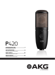
1
D-01
Bedienungsanleitung
digitales mikrophon
2
Operating Instructions
digital microphone
8
georg neumann gmbh · ollenhauerstr. 98 · 13403 berlin · germany
fon +49 (0)30 / 41 77 24-0 · fax -50 · [email protected] · www.neumann.com
1.
geschlossen wird. Das D-01 ist gegen Überspannung geschützt und verträgt kurzzeitig bis +55 V.)
Einleitung
In dieser Anleitung finden Sie alle wichtigen Informationen für den Betrieb und die Pflege des von
Ihnen erworbenen Mikrophons. Lesen Sie diese
Anleitung und die der dazugehörigen Geräte bitte
sorgfältig und vollständig, bevor Sie es benutzen.
Bewahren Sie die Anleitung bitte so auf, dass sie
für alle momentanen und späteren Nutzer jederzeit zugänglich ist.
• Reparatur- und Servicearbeiten dürfen nur von
erfahrenem und autorisiertem Fachpersonal
durchgeführt werden. Wenn Sie das Mikrophon
eigenmächtig öffnen oder umbauen, erlischt
die Gewährleistung.
• Verwenden Sie das Mikrophon nur in dem in
den technischen Daten angegebenen Leistungsbereich.
• Lassen Sie das Mikrophon auf Umgebungstemperatur akklimatisieren, bevor Sie es einschalten.
• Nehmen Sie das Mikrophon nicht in Betrieb,
wenn es beschädigt ist.
• Verlegen Sie Kabel stets so, dass niemand darüber stolpern kann.
• Halten Sie Flüssigkeiten vom Mikrophon und
dessen Anschlüssen fern.
• Verwenden Sie zum Reinigen keine Lösungsmittel oder aggressiven Reinigungsmittel.
• Entsorgen Sie das Mikrophon nach den Bestimmungen Ihres Landes.
Weitergehende Informationen, insbesondere
auch zu den verfügbaren Zubehörteilen und den
Neumann-Servicepartnern, finden Sie auf unserer
Website www.neumann.com. Die Servicepartner
können Sie auch telefonisch unter +49 (0) 30 /
41 77 24 – 0 erfragen.
Auf unserer Website www.neumann.com finden
Sie in der Rubrik Downloads ergänzend folgende
PDF-Dateien:
• Hinweise zur Pflege des Mikrophons
• Bedienungsanleitung DMI-2 (Digitales Mikrophon-Interface)
• Bedienungsanleitung RCS (Remote Control
Software)
• Kurzbeschreibung des Standards AES 42
Weitergehende Informationen zur Schnittstelle
digitaler Mikrophone finden Sie bei www.aes.org/
standards unter „AES 42-2006: AES standard for
acoustics – Digital interface for microphones“.
Zum weltweiten Erfahrungsaustausch unter
Neumann-Anwendern bieten wir das Neumann
Online-Forum an, das sich durch die integrierte
Archivfunktion zu einem umfangreichen KnowHow-Pool entwickelt hat.
2.
Das D-01 ist ein Studio-Kondensatormikrophon
mit digitalem Ausgang gemäß dem internationalen
Standard AES 42. Dieser basiert auf dem in Studiogeräten üblichen Standard AES 3 (AES/EBU)
für digitale Audiosignale, erweitert um die Phantomspeisung für das Mikrophon, um Fernsteuerund Synchronisationsdaten sowie um User-Bits
zum Empfang von Mikrophon-Steuerdaten.
Das D-01 ist ein Großmembranmikrophon mit umschaltbarer Richtcharakteristik, von Kugel, breite
Niere, Niere, Hyperniere bis Acht, sowie 10 weiteren Zwischenstellungen.
Sicherheitshinweise
Die Einsprechrichtung des Mikrophons ist seitlich,
die Vorderseite wird durch das Neumann-Emblem
gekennzeichnet.
Schließen Sie das Mikrophon nur an Mikrophoneingänge und Speisegeräte an, die eine
Phantomspeisung nach AES 42 liefern.
(Das Mikrophon wird jedoch nicht beschädigt,
falls es versehentlich kurzzeitig an einen analogen
Mikrophoneingang mit 48 V-Phantomspeisung an-
2
Beschreibung
Registrieren Sie bitte Ihr System auf der Website
www.my-Solution-D.com, um jederzeit über Updates informiert zu werden!
Der bestimmungsgemäße Gebrauch dieses Mikrophons ist die Wandlung akustischer in digitale
elektrische Signale.
D
3.
Bei der im Mikrophonkorb elastisch gelagerten
Großmembrankapsel handelt es sich um die ebenfalls neu entwickelte Kapsel K 07.
Die K 07 im Zusammenhang mit der MikrophonEingangsschaltung und der neuartigen Wandlertechnologie ist das erste Doppelmembransystem,
das einen Ersatzgeräuschpegel von nur 8 dB-A
bietet.
Das Mikrophon zeichnet sich aus durch besonders saubere und verfärbungsfreie Klangübertragung bei sehr niedrigem Eigengeräuschpegel
und gleichzeitig höchster Aussteuerbarkeit. Es
verwendet zur Digitalisierung ein von Neumann
entwickeltes und patentiertes A/D-Wandlungsverfahren. Dadurch ist sichergestellt, dass der
gesamte Dynamikumfang der Kapselsignale in
die digitale Ebene überführt wird. Mit der integrierten digitalen Signalverarbeitung bietet das
Mikrophon außerdem Funktionen, die bisher nur
im Mischpult oder zusätzlichen Geräten realisiert
werden konnten. Diese Funktionen werden im Kapitel Technische Daten beschrieben.
Der Kapseldurchmesser beträgt 30 mm, die Dicke
des Kapselsystems 4,5 mm. Beide Membranen
liegen dicht an der Kapsel-Oberfl äche, um interne Laufzeiten des Schalls, seine Wege um das
Kapselsystem herum sowie Reflexionen an den
Membran-Spannringen zu minimieren.
Das Ergebnis sind sehr flache, ausgeglichene Frequenzgänge für alle 15 im Mikrophon D-01 wählbaren Richtcharakteristiken.
Im oberen Formantbereich ab 3 kHz ist die Kapsel
breitbandig etwa 2 dB empfindlicher als in den Lagen darunter. Dies gibt ihr einen frischen, offenen
Klang ohne Verfärbungen.
Die K 07 arbeitet mit einem besonders kleinen
Membranabstand. Dieser sorgt für eine wirksame,
rein akustische Bedämpfung des Systems. Da zum
Erreichen der Mikrophoneigenschaften keine Resonanzwirkungen genutzt werden, ist das Impulsverhalten des Mikrophons ausgezeichnet, und
es vermag alle Ausgleichsvorgänge in Musik und
Sprache unverfälscht zu übertragen.
Die Kapsel ist zum Schutz gegen Körperschallübertragung elastisch gelagert. Durch den bis unter
20 Hz linear verlaufenden Frequenzgang des D-01
können auch extrem niederfrequente Signale
unverfälscht übertragen werden. Andererseits
ist das Mikrophon dadurch auch empfindlich für
tieffrequente Störsignale wie Körperschall, Poppund Windgeräusche. Bei eventuellen Störungen
empfiehlt es sich daher, entweder den Frequenzgang im unteren Bereich zu beschneiden (siehe
Abschnitt 4.2, Software-Funktionen) und/oder
einen Popschirm PS 20 a oder einen Windschutz
WS 47 zu verwenden (siehe Zubehör, Kapitel 7).
Die Richtcharakteristik der Kapsel kann über die
RCS-Software in 15 Stufen verändert und das Mikrophon damit besonders feinfühlig den Aufnahmegegebenheiten angepasst werden.
Der 3-polige XLR-Ausgang des Mikrophons ist
nach AES 42 beschaltet und mechanisch kompatibel zu der bekannten analogen Anschlusstechnik.
Dies hat den Vorteil, dass analoge Mikrophonkabel bis zu einer mittleren Entfernung von etwa
100 m eingesetzt werden können. Bei versehentlichem Aufstecken auf einen phantomgespeisten
analogen Mikrophoneingang ist das D-01 durch
eine Überspannungsschutzschaltung gegen Beschädigung geschützt.
Steht zum Anschluss des Mikrophons kein AES 42Eingang (z. B. am Mischpult) zur Verfügung, bietet
Neumann das zweikanalige Digitale MikrophonInterface (DMI-2) mit der dazugehörigen Steuersoftware RCS zur Fernsteuerung aller Mikrophoneigenschaften an (siehe auch Kapitel Technische
Daten).
4.
Inbetriebnahme
Mikrophon einrichten
Befestigen Sie das Mikrophon auf einem ausreichend stabilen und standfesten Stativ. Verwenden
Sie ggf. eine elastische Aufhängung, um die Übertragung von Körperschallgeräuschen mechanisch
zu unterdrücken. Setzen Sie dafür das Mikrophon
von oben in den Innenkorb ein und schrauben
Sie es mit der Rändelmutter am Innenkorb fest.
Zur Dämpfung von Wind- oder Popgeräuschen
verwenden Sie bei Bedarf einen Wind- oder Popschutz aus unserem Zubehörprogramm.
Mikrophon anschließen
Vorsicht: Eine falsche Versorgungsspannung
kann das Mikrophon beschädigen!
Schließen Sie das Mikrophon nur an Mikrophoneingänge und Speisegeräte an, die eine Phantomspeisung nach AES 42 liefern. Siehe auch Kapitel
„Sicherheitshinweise“.
Vorsicht: Sehr hohe Signalpegel können Ihr
Gehör und Ihre Laut sprecher schädigen!
Reduzieren Sie an den angeschlossenen Wiedergabegeräten die Lautstärke, bevor Sie das Mikrophon anschließen, auch wegen der Gefahr der
akustischen Rückkopplung.
3
D
Verbinden Sie das Mikrophon über ein XLR-Kabel
mit dem AES 42-Mikrophoneingang Ihres Digitalen Mikrophon-Interface DMI-2 (siehe auch die
Anleitungen für DMI-2 und RCS) oder eines anderweitigen Audiogerätes nach AES 42.
verschoben. Während des Umladens ist das Mikrophon kurzzeitig stumm geschaltet.
Gain: Die Verstärkung erfolgt ausschließlich auf
der digitalen Ebene und führt damit nicht zu der
aus der analogen Signalbearbeitung bekannten
Rauschaddition und zu möglichen Klangbeeinflussungen. Das Schalten erfolgt knackfrei.
Eine blaue LED im Mikrophon zeigt bei korrekter
Speisung die Betriebsbereitschaft an. Sie leuchtet beim Einschalten zunächst schwach und nach
kurzer Zeit mit der voreingestellten Helligkeit.
Diese kann bei Verwendung des Digitalen Mikrophon-Interfaces DMI-2 mit der Remote Control
Software in vier Stufen variiert und ausgeschaltet
werden.
Peak-Limiter: Der sehr schnelle Peak-Limiter hat
eine einstellbare Ansprechschwelle und verhindert Übersteuerungen bzw. Clippen des Audiosignals im Signalweg.
Kompressor/Limiter: Weiterhin ist ein vollständig
parametrisierbarer Kompressor/Limiter implementiert. Dieser kann breitbandig oder als Hochtonkompressor/Limiter (De-Esser) in einem von
drei wählbaren Frequenzbereichen arbeiten. Alle
wichtigen Parameter sind einstellbar.
Achten Sie beim Anschließen von Kabeln auf die
korrekte Verriegelung der Steckverbinder.
Lange Kabel und mehrfache Steckverbindungen
führen zu einem Spannungsabfall der Speisespannung und zu einer Verschlechterung des JitterVerhaltens insbesondere bei hohen Abstastraten.
Verwenden Sie daher möglichst durchgehende Kabelverbindungen zwischen Mikrophon und Folgegerät und bei größeren Distanzen ausschließlich
AES/EBU-Kabel (Wellenwiderstand 110 Ohm).
Achten Sie darauf, dass das Mikrophon und alle
Geräte der digitalen Signalkette synchronisiert
sind. Wird das Digitale Mikrophon-Interface von
Neumann verwendet, sollten die angeschlossenen
Mikrophone immer im Synchronmode (Mode 2)
betrieben werden, unabhängig davon, ob in der
nachfolgenden Signalkette Sample Rate Converter im Einsatz sind. Auf diese Weise wird im DMI
eine sehr effektive Jitterunterdrückung wirksam.
Auch ist die Ausgabe zweier Mikrophonsignale in
einem AES 3-Stereosignal nur möglich, wenn die
Mikrophone untereinander synchron laufen.
Parameter, die über die AES 42-Schnittstelle
ferngesteuert werden können
Richtcharakteristik: Die Umschaltung der Richtcharakteristik wird durch Veränderung der Polarisationsspannung der hinteren Kapselhälfte realisiert. Während des Umladens ist das Mikrophon
kurzzeitig stumm geschaltet.
Low Cut: Der Low Cut bietet gemäß AES42-Standard die vier Einstellungen: off, 40 Hz, 80 Hz und
160 Hz.
Vordämpfung: Die Vordämpfung wird durch
Reduktion der Kapselspannung realisiert. Bei
Aktivierung wird der Dynamikbereich um den
entsprechenden Wert zu höheren Schalldrücken
D
4
Außerdem lassen sich die Abtastrate, der Synchronisationsmodus, Testsignale, die Polarität
und Stummschaltung des Ausgangssignals und
die LEDs fernsteuern.
Die Software im Mikrophon kann über das Neumann DMI-2 aktualisiert werden, so dass Erweiterungen der Software auch bestehenden Kunden
zur Verfügung stehen. Zu Details des Updates lesen Sie bitte die RCS-Anleitung.
5.
Außerbetriebnahme und Aufbewahrung
Ziehen Sie beim Lösen von Kabeln stets nur an
den Steckverbindern und nicht am Kabel.
Mikrophone, die längere Zeit nicht verwendet
werden, sollten bei normalem Umgebungsklima
staubgeschützt aufbewahrt werden. Verwenden
Sie hierfür einen nicht fusselnden, luftdurchlässigen Staubschutzbeutel oder die Originalverpackung des Mikrophons.
6.
Technische Daten
Fernsteuerbare Funktionen
1)
Zulässige klimatische Verhältnisse:
Betriebstemperaturbereich.............. 0 °C … +40 °C
Lagerungstemperaturbereich ...... –20 °C … +70 °C
Feuchtebereich ......................0 % … 99 % rel. hum.
bei +20 °C
0 % … 95 % rel. hum.
bei +60 °C
Vordämpfung .............................. 0/–6/–12/–18 dB
Hochpassfilter ........................... Off/40/80/160 Hz
Digitale Signalverstärkung .......................0...63 dB
in 1 dB-Schritten, knackfrei
Testsignal ............................ Off, 1 kHz (–48 dBFS),
rosa Rauschen (–35 dBFS),
weißes Rauschen (–43 dBFS)
Akust. Arbeitsweise ................... DoppelmembranDruckgradientenempfänger
Richtcharakteristik ................Kugel...Niere...Acht,
insgesamt 15 Stellungen
Übertragungsbereich ......................20 Hz...20 kHz
Feldübertragungsfaktor2) ....................... –44 dBFS
Kompressor/Limiter ......................................On/Off
Untere Grenzfrequenz
des Arbeitsbereichs ...........Flat/1 kHz/2 kHz/4 kHz
Max. Dämpfung (gain reduction):
flat mode ....................................................... > 63 dB
1 kHz/2 kHz/4 kHz ........................................ > 20 dB
Ratio ............................................... 1,2:1/1,5:1/2:1/
3:1/4:1/6:1/8:1/>100:1
Threshold .........................–63 dBFS..–10...0 dBFS,
in 1 dB Stufen
Attack time ..............0/0,1/0,3/1/3/10/30/100 ms
Release time .................. 0,05/0,1/0,2/0,5/1/2/5 s
Ersatzgeräuschpegel,
CCIR4) ...............................................................19 dB
Ersatzgeräuschpegel,
A-bewertet4) ..................................................8 dB-A
Geräuschpegelabstand3),
CCIR4) ...............................................................75 dB
Geräuschpegelabstand3),
A-bewertet4) ................................................... 86 dB
Grenzschalldruckpegel
bei 0 dBFS ............................................. 138 dBSPL
Dynamikumfang4) .........................................130 dB
A/D-Wandlung ........................Neumann-Verfahren
(patentiert), 28 Bit
interne Wortbreite
Digitale Signalverarbeitung ......Fixpoint, variable
interne Wortbreite,
28...60 Bit
Abtastraten ......................................44,1/48/88,2/
96/176,4/192 kHz
Ausgangsdatenformat ...........24 Bit nach AES/EBU
(AES 3)
Bei 0 dB Vordämpfung und 0 dB Gain.
1)
Alle Werte für nicht-kondensierende Feuchtigkeit.
2)
bei 1 kHz, 0 dB Verstärkung und 94 dB SPL
3)
bezogen auf 94 dB SPL
4)
nach IEC 60268-1;
CCIR-Bewertung nach CCIR 468-3, Quasi-Spitzenwert;
A-Bewertung nach IEC 61672-1, Effektivwert
(bezogen auf eine Pegeländerung von ca. 10 dB )
Peak-Limiter...................................................On/Off
Attack time ...................................–160 µs (negativ)
Release time ............................. ca. 50 ms...150 ms
(signalabhängig)
Threshold ........................................Off: 0 dBFS fest
On: –15 dBFS...0 dBFS,
in 1 dB-Stufen
Mute................................................................On/Off
Phase (Polarität) ......................................... 0, 180°
Anzeige .............................LED 1 (rot), LED 2 (blau),
Helligkeit einstellbar
Abtastraten .......44,1/48/88,2/96/176,4/192 kHz
Latenzzeit:
44,1/48 kHz .......................................... 52 Samples
88,2/96 kHz.......................................... 61 Samples
176,4/192 kHz......................................121 Samples
Synchronisation:
asynchroner Betrieb (freilaufend),
Frequenz-Grundgenauigkeit.................... ± 25 ppm
synchroner Betrieb,
Ziehbereich .................................... min. ± 100 ppm
Stromversorgung
(Phantomspeisung gemäß AES 42)
Speisespannung .................................. +6...+10,5 V
Stromaufnahme ..................................max. 220 mA
Steckverbinder ............................................ XLR 3 M
Abmessungen ...............................Ø 63,5 x 185 mm
Gewicht ...........................................................700 g
5
D
7.
Zubehör* (Fotos im Anhang)
Elastische Aufhängung
EA 2 ..........................ni ................ Best.-Nr. 008432
Tisch- und Fußbodenständer
MF 3 .........................sw ............... Best.-Nr. 007321
MF 4 .........................sw ............... Best.-Nr. 007337
MF 5 .........................gr ................ Best.-Nr. 008489
Mikrophonneigevorrichtung
MNV 87 ....................ni ................ Best.-Nr. 006804
Stativgelenke, weitere mechanische Adapter
DS 120 .....................sw ............... Best.-Nr. 007343
SG 1 ..........................sw ............... Best.-Nr. 008445
Popschutz
PS 15 .......................sw ............... Best.-Nr. 008472
PS 20 a ...................sw ............... Best.-Nr. 008488
Anschlusskabel
IC 3 mt .....................sw ............... Best.-Nr. 006543
IC 4 ..........................ni ................ Best.-Nr. 006547
D
6
Fehlercheckliste*
Fehler
▶ Mögliche Ursachen
▶ Abhilfe
Keine
Funktion /
Keine Signalübertragung
Speisespannung fehlt
Überprüfen Sie das Speisegerät und ggf. die
zugehörigen Software-Einstellungen
(RCS -> System -> MicPWR).
Das Mikrophon ist nicht mit
einem AES 42-Eingang verbunden
Verwenden Sie einen AES 42–Eingang.
Das Mikrophon ist nicht mit dem
richtigen Kanal verbunden
Überprüfen Sie den Signalweg.
Der Kanal ist gemutet
Deaktivieren Sie Mute in der AES 42-Fernsteuerung.
Zu hohe Schalldrücke im
aufzunehmenden Tonsignal
Vergrößern Sie den Aufnahmeabstand oder aktivieren
Sie die Vordämpfung in Ihrer AES 42-Fernsteuerung.
Übersteuerung durch tieffrequente Störgeräusche
(Trittschall, Wind)
Benutzen Sie einen geeigneten Windschutz (Zubehör).
Aktivieren Sie die Vordämpfung in Ihrer AES 42-Fernsteuerung.
Bedeutung der Farbcodierungen:
ni = nickel, sw = schwarz, gr = grau
* Ausführliche Beschreibungen und weitere Artikel finden Sie
in unserem Zubehörkatalog oder unter www.neumann.com
Ton verzerrt /
schlechte
Signalqualität
Schaumstoff windschutz
WS 47 .......................sw ............... Best.-Nr. 006826
8.
9.
Lieferumfang
Mono-Set
Stereo-Set
Mikrophon
Mikrophon D-01
2 Mikrophone D-01
Mikrophon D-01
Elast. Aufhängung EA 2
2 Elast. Aufhängungen EA 2
Interface DMI-2
Interface DMI-2
Adapter USB 485
Adapter USB 485
Bedienungsanleitungen
Bedienungsanleitungen
Bedienungsanleitung
Aluminiumkoffer
Aluminiumkoffer
Holzetui
Kabel IC 3
2 Kabel IC 3
Kabel RJ 45
Kabel RJ 45
Kabel BNC
Kabel BNC
Kabel USB
Kabel USB
Netzkabel
Netzkabel
Aktivieren Sie ggf. den entsprechenden Eingang auf
dem zugeordneten Kanalzug des Mischpults.
Benutzen Sie einen geeigneten Popschutz (Zubehör).
Aktivieren Sie die Vordämpfung in Ihrer AES 42-Fernsteuerung.
*
Weitere Fehlermöglichkeiten sind in der Bedienungsanleitung zum DMI-2 erläutert.
7
D
1.
Introduction
This manual contains essential information for
the operation and care of the microphone you
have purchased. Please read these instructions
and those of the connected devices carefully and
completely before using the product. Please keep
this manual where it will be accessible at all times
to all current and future users.
Additional information, in particular concerning available accessories and Neumann service
partners, can be found on our website: www.neumann.com. Information about service partners
can also be obtained by telephone: +49 (0) 30 /
41 77 24 - 0.
The following related files are available in PDF
format in the Downloads section of our website
www.neumann.com:
• Some Remarks on Microphone Maintenance
• DMI-2 Digital Microphone Interface Operating
Manual
• RCS Remote Control Software Operating Manual
• Short description of the AES 42 standard
Additional information concerning the digital microphone interface can be found on the website:
www.aes.org/standards “AES 42-2006: AES standard for acoustics – Digital interface for microphones”.
Our Neumann online forum enables Neumann
users worldwide to share their experiences.
Through its integrated archive function, the forum
has developed into an extensive knowledge pool.
Please register your system on the website www.
my-Solution-D.com, to be informed whenever updates are available!
2.
Safety instructions
The microphone has the intended purpose of
converting acoustic signals into digital electrical
signals.
EN
8
3.
can handle a voltage of up to +55 V for a short period.)
to reduce reflections from the rings tensioning
the diaphragm.
• Repairs and servicing are to be carried out only
by experienced, authorized service personnel.
Unauthorized opening or modification of the
microphone shall void the warranty.
• Use the microphone only under the conditions
described in the Technical Data.
• Allow the microphone to adapt to the ambient
temperature before switching it on.
• Do not operate the microphone in a damaged
condition.
• Always run cables in such a way that there is no
risk of tripping over them.
• Ensure that liquids are kept at a safe distance
from the microphone and its connections.
• Do not use solvents or aggressive cleansers for
cleaning purposes.
• Dispose of the microphone in accordance with
the regulations applicable to the respective
country.
The resulting frequency responses of the D-01 microphone are very flat and smooth for all 15 available polar patterns.
Description
The D-01 is a studio condenser microphone with a
digital output that complies with the international standard AES 42. Based upon the usual AES 3
(AES/EBU) standard for digital audio signals in
studio equipment, this standard has been extended to include phantom power for the microphone,
remote control and synchronization data, and
user bits for receiving microphone control data.
The D-01 is a large diaphragm microphone with
switchable polar pattern: omni, wide cardioid,
cardioid, hypercardioid, figure-8, as well as 10
intermediate settings.
The microphone is addressed from the side. The
front side is designated by the Neumann logo.
The capsule is the newly developed K 07 large diaphragm capsule. It is elastically mounted inside
the microphone head grille.
Connect the microphone only to microphone
inputs and to equipment which supplies phantom power in accordance with AES 42.
The K 07, together with the microphone input circuitry and the new A/D conversion technology, is
the first double diaphragm system to provide an
equivalent self noise level of only 8 dB-A.
(But the microphone will not be damaged if it is
accidentally connected to an analog microphone
input with a phantom power of 48 V for a short
period. The D-01 has overvoltage protection and
The capsule diameter is 30 mm, and the thickness
of the capsule system is 4.5 mm. Both diaphragms
lie very close to the capsule surface in order to
minimize internal and external path lengths, and
of the capsule signal is transferred to the digital
domain. The integrated digital signal processing
also provides functions which were previously
available only via a mixing console or additional
studio equipment. These functions are described
in the “Technical data” section.
In the upper formant range above 3 kHz the capsule is more sensitive by approximately 2 dB. This
ensures a fresh, open sound character without
coloration.
The K 07 operates with an especially small distance between diaphragms and electrodes. This
provides for an efficient, purely acoustical damping of the system. As the microphone characteristics are obtained without resorting to corrective resonance effects, the impulse response of
the microphone is excellent, and it transmits all
transient signals in music and speech without any
coloration.
The capsule is mounted elastically to attenuate
vibration noise. Since the frequency response of
the D-01 is linear down to below 20 Hz, even very
low frequency signals can be transmitted without
coloration. However this implies that the microphone is also sensitive to low frequency noise signals such as structure-borne, pop and wind noise.
To avoid interference it is therefore advisable to
use the microphone low cut filter (see Section 4.2
”Software Functions“) and/or to use a PS 20 a pop
screen or a WS 47 windscreen (see Section 7 ”Accessories“).
The directional characteristic of the capsule can
be set to any of 15 polar patterns via RCS-software, allowing a particularly fine adjustment of
the microphone to recording conditions.
If there is no microphone input according to
AES 42 standard available Neumann provides the
two-channel Digital Microphone Interface (DMI-2)
with the accompanying RCS control software for
remote controlling all microphone characteristics
(see also the “Technical data” section).
4.
Setup
Mounting the microphone
Attach the microphone to a stable, sturdy stand.
Use an elastic suspension, if necessary, for the
mechanical suppression of structure-borne noise.
For this purpose set the microphone into the inner
cage from above, and secure it to the inner cage
with the threaded nut. If required, use a windscreen or popscreen from our range of accessories in order to suppress wind or pop noise.
Connecting the microphone
Caution: An incorrect supply voltage can damage the microphone!
Connect the microphone to microphone inputs
and to equipment which supplies phantom power in accordance with AES 42. See also chapter
“Safety Instructions”.
Caution: Very high signal levels can damage
loudspeakers and your hearing!
The 3-pin XLR output of the microphone is configured according to AES 42-2001 and is mechanically compatible with the similar connections of
analog microphones. This has the advantage of
allowing analog microphone cables to be used for
runs of up to approximately 100 m. Over-voltage
protection prevents damage to the D-01 in the
event that it is inadvertently connected to a phantom-powered analog microphone input.
Reduce the volume of connected playback equipment before connecting the microphone. This is
also advisable in order to avoid acoustic feedback.
The microphone features exceptionally clean
sound transmission which is free of coloration,
with very low self-noise and an extensive dynamic
range. Digitization is performed by an A/D conversion process developed and patented by Neumann. This ensures that the full dynamic range
With a correct power supply, a blue LED on the microphone indicates that the microphone is ready
to operate. After switching on, the LED at first
glows dimly, and after a short time shines with
the preset brightness. When the DMI-2 Digital Microphone Interface is used with the Remote Con-
Connect the microphone by means of an XLR cable
to the AES 42 microphone input of the DMI-2 Digital Microphone Interface (see also DMI-2 and RCS
manuals) or to other audio equipment complying
with the AES 42 standard.
9
EN
trol Software, the LEDs can be set to four different
brightness levels or switched off.
(de-esser) in one of three selectable frequency
ranges. All important parameters are adjustable.
When connecting the cables, ensure that the connectors are locked correctly.
In addition, the sampling rate, the synchronization mode, test signals, the polarity and muting of
the output signal and the LEDs can be controlled
remotely.
Long cables and multiple connectors lead to a
drop in the supply voltage and to a deterioration
in jitter behavior, particularly in the case of high
sampling rates. Therefore, to the greatest extent
possible, use continuous cable between the microphone and subsequent equipment, and for
longer distances use AES/EBU cable exclusively
(with an impedance of 110 ohms).
Ensure that the microphone and all equipment in
the digital signal chain are synchronized. If the
Neumann Digital Microphone Interface is used,
the connected microphones should always be operated in synchronous mode (Mode 2), whether or
not sample rate converters are used in the subsequent signal chain. This will ensure very effective
jitter suppression in the DMI. Also, the output of
two microphone signals as one AES 3 stereo signal is possible only if the microphones are synchronized with one another.
Parameters which can be remote controlled
via the AES 42 interface
Polar pattern: Switching the polar pattern is
achieved by varing the polarization voltage of the
rear capsule half. During the reloading process
the microphone is temporarily muted.
Low Cut: Acccording to AES42 there are four setting for the low cut: off, 40 Hz, 80 Hz and 160 Hz.
Pre-attenuation: Pre-attenuation is achieved by
reducing the capsule voltage. If pre-attenuation is
activated, the dynamic range is shifted by the corresponding value to higher sound pressure levels.
During the reloading process the microphone is
temporarily muted.
Gain: Gain is carried out exclusively in the digital
domain, thus avoiding the additional noise and
possible effects on the sound which can occur in
analog processing. The switching process is clickless.
Peak limiter: The very fast peak limiter has an adjustable threshold, and prevents overloading or
clipping of the audio signal in the signal path.
Compressor/Limiter: As well, a compressor/limiter with completely adjustable parameters is
provided. It can function over a broad frequency
range, or as a high-frequency compressor/limiter
EN
10
The software in the microphone can be updated
via the Neumann DMI-2. Therefore software updates are also available to existing customers.
Please refer to the RCS manual for details concerning the updates.
5.
Shutdown and Storage
When disconnecting a cable, always pull only on
the connector and not on the cable itself.
Microphones which are unused for prolonged
periods should be stored under normal ambient
atmospheric conditions, and should be protected
from dust. For this purpose, use a lint-free, airpermeable dust cover or the original packaging of
the microphone.
6.
Technical data
Remote controlled functions
1)
Permissible atmospheric conditions
Operating temperature range.......... 0 °C to +40 °C
Storage temperature range ...........–20 °C to +70 °C
Humidity range .....................0 % to 99 % at +20 °C
0 % … 95 % at +60 °C
Acoustical op. principle ............Double diaphragm
pressure gradient transducer
Directional
pattern.......................... Omni...cardioid...figure-8,
15 patterns in total
Frequency range ............................ 20 Hz to 20 kHz
Sensitivity2) ............................................. –44 dBFS
Equivalent noise level,
CCIR4) ...............................................................19 dB
Equivalent noise level,
A-weighted4) ..................................................8 dB-A
Signal-to-noise ratio3),
CCIR4) ...............................................................75 dB
Signal-to-noise ratio3),
A-weighted4) ................................................... 86 dB
Maximum SPL
at 0 dBFS3) ............................................. 138 dBSPL
Dynamic range
including capsule4) .......................................130 dB
A/D conversion ...........................Neumann process
(patented), 28-bit
internal word length
Digital signal processing ..... Fixed-point, variable
internal word length
28 bits to 60 bits
Sampling rates .................................44,1/48/88,2/
96/176,4/192 kHz
Output data format ............................ 24 bits as per
AES/EBU (AES 3)
At 0 dB pre-attenuation and 0 dB gain.
1)
All values are for non-condensing humidity.
2)
at 1 kHz, 0 dB gain, and 94 db SPL
3)
re 94 dB SPL
4)
according to IEC 60268-1;
CCIR-weighting acccording to CCIR 468-3, quasi peak;
A-weighting according to IEC 61672-1, RMS
Pre-attenuation .......................... 0/–6/–12/–18 dB
High-pass filter .......................... Off/40/80/160 Hz
Digital gain.................................................0...63 dB
in steps of 1 dB, clickless
Test signals .......................... Off, 1 kHz (–48 dBFS),
pink noise (–35 dBFS),
white noise (–43 dBFS)
Compressor/Limiter ......................................On/Off
Lower cut-off frequency
of the working range ..........Flat/1 kHz/2 kHz/4 kHz
Max. gain reduction:
Flat mode ...................................................... > 63 dB
1 kHz/2 kHz/4 kHz ........................................ > 20 dB
Compression ratio ..........................1.2:1/1.5:1/2:1/
3:1/4:1/6:1/8:1/>100:1
Threshold .........................–63 dBFS..–10...0 dBFS,
in steps of 1 dB
Attack time ..............0/0.1/0.3/1/3/10/30/100 ms
Release time .................. 0.05/0.1/0.2/0.5/1/2/5 s
(for a level change of approx. 10 dB )
Peak limiter ....................................................On/Off
Attack time .................................–160 µs (negative)
Release time .................. approx. 50 ms to 150 ms
(signal-dependent)
Threshold ......................................Off: 0 dBFS fixed
On: –15 dBFS to 0 dBFS,
in steps of 1 dB
Mute................................................................On/Off
Phase (polarity) ......................................... 0°, 180°
Signal light ...................... LED 1 (red), LED 2 (blue),
brightness adjustable
Sampling rates ..44.1/48/88.2/96/176,4/192 kHz
Latency:
44.1/48 kHz ...........................................52 samples
88.2/96 kHz ...........................................61 samples
176,4/192 kHz...................................... 121 samples
Synchronization
Asynchronous operation (free-running),
frequency stability ................................... ± 25 ppm
Synchronous operation,
pulling range .................................. min. ± 100 ppm
Power supply
(phantom power complying with AES 42)
Supply voltage range ...................... +6 V to +10.5 V
Current consumption .........................max. 220 mA
Connector..................................................... XLR 3 M
Dimensions ...................................Ø 63.5 x 185 mm
Weight .............................................................700 g
11
EN
7.
Accessories* (see photos in appendix)
Elastic Suspensions
EA 2 ..........................ni ..................Cat. No. 008432
Table and Floor Stands
MF 3..........................blk ................Cat. No. 007321
MF 4 .........................blk ................Cat. No. 007337
MF 5 .........................gry ................Cat. No. 008489
Auditorium Hanger
MNV 87 ....................ni ..................Cat. No. 006804
Stand Mounts, Misc. Mechanical Adapters
DS 120 .....................blk ................Cat. No. 007343
SG 1 ..........................blk ................Cat. No. 008445
Popscreen
PS 15 .......................blk ................Cat. No. 008472
PS 20 a ...................blk ................Cat. No. 008488
Connecting Cables
IC 3 mt ....................blk ................Cat. No. 006543
IC 4 ...........................ni ..................Cat. No. 006547
Troubleshooting*
Problem
▶ Possible causes
▶ Solution
Microphone not
operating /
No signal
transmission
Supply voltage not activated
Check the power supply device and if necessary
the associated software settings (RCS -> System ->
MicPWR).
The microphone is not connected
to an AES 42 input
Use an AES 42 input.
The microphone is not connected
to the correct channel
Check the signal path.
The channel is muted
Deactivate the mute in the AES 42 remote control.
Excessive sound pressure of the
signal to be recorded
Take a more distant microphone position or activate
the pre-attenuation in the AES 42 remote control.
Overload due to low-frequency
interference (e.g. impact sound
or wind)
Use an appropriate windscreen (accessory). Activate
the pre-attenuation in the AES 42 remote control.
Meaning of color codes:
ni = nickel, blk = black, gry = grey
* Detailed descriptions and additional articles can be found
in our accessories catalog or at: www.neumann.com
Distorted
sound /
bad signal
quality
Foam Windscreens
WS 47 .......................blk ................Cat. No. 006826
8.
9.
Scope of delivery
Mono set
Stereo set
Microphone
D-01 microphone
2 D-01 microphones
D-01 microphone
EA 2 elast. suspension
2 EA 2 elast. suspensions
*
EN
DMI-2 interface
DMI-2 interface
USB 485 converter
USB 485 converter
Operating manuals
Operating manuals
Operating manual
Aluminium case
Aluminium case
Wooden case
IC 3 cable
2 IC 3 cable
RJ 45 cable
RJ 45 cable
BNC cable
BNC cable
USB cable
USB cable
AC line cable
AC line cable
12
If necessary, activate the appropriate input on the
corresponding channel of the mixing console.
Use an appropriate popscreen (accessory). Activate
the pre-attenuation in the AES 42 remote control.
Please see also the manual of the DMI-2 for further trouleshootings.
13
EN
10. Frequenz- und Polardiagramme
10. Frequency responses and polar patterns
gemessen im freien Schallfeld nach IEC 60268-4, Toleranz ±2 dB
measured in free-fi eld conditions (IEC 60268-4), tolerance ±2 dB
14
15
®
EA 2
MF 3
MF 4
MF 5
MNV 87
DS 120
SG 1
WS 47
PS 15
PS 20 a
IC 3 mt
IC 4
Konformitätserklärung
Declaration of Conformity
Die Georg Neumann GmbH erklärt, dass dieses Gerät
die anwendbaren CE-Normen und -Vorschriften erfüllt.
Neumann ist in zahlreichen Ländern eine eingetragene
Marke der Georg Neumann GmbH.
Georg Neumann GmbH hereby declares that this device
conforms to the applicable CE standards and regulations.
Neumann is a registered trademark of the
Georg Neumann GmbH in certain countries.
®
Irrtümer und technische Änderungen vorbehalten • Errors excepted, subject to changes
Printed in Germany • Publ. 10/07 514790/A02