1
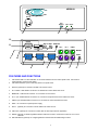
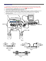
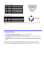
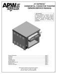
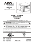
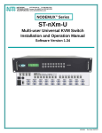
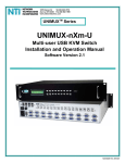
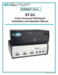
KEEMUX® Series KEEMUX-P2 (2-Port PS/2 KVM Switch) INSTALLATION / USER GUIDE MAN049 Rev Date 4/8/2004 WARRANTY INFORMATION The warranty period on this product (parts and labor) is two (2) years from the date of purchase. Please contact Network Technologies Inc at (800) 742-8324 (800-RGB-TECH) in the US and Canada or (330) 562-7070 (worldwide) or at our website at http://www.networktechinc.com for information regarding repairs and/or returns. A return authorization number is required for all repairs/returns. COPYRIGHT Copyright© 2004 by Network Technologies Inc. All rights reserved. No part of this publication may be reproduced, stored in a retrieval system, or transmitted, in any form or by any means, electronic, mechanical, photocopying, recording, or otherwise, without the prior written consent of Network Technologies Inc, 1275 Danner Drive, Aurora, OH 44202 CHANGES The material in this guide is for information only and is subject to change without notice. Network Technologies Inc reserves the right to make changes in the product design without reservation and without notification to its users. TABLE OF CONTENTS INTRODUCTION ............................................................................................................................................................................... 1 MATERIALS...................................................................................................................................................................................... 1 FEATURES AND FUNCTIONS......................................................................................................................................................... 2 INSTALLATION ................................................................................................................................................................................ 3 Units with audio support (optional)............................................................................................................................................ 4 Power-Up Sequence .................................................................................................................................................................... 4 Power-Down Sequence ............................................................................................................................................................... 4 USING THE NTI SWITCH ................................................................................................................................................................. 4 Front Panel Control ..................................................................................................................................................................... 4 Keyboard Control......................................................................................................................................................................... 5 COMMAND Mode ..................................................................................................................................................................... 5 SCAN Mode .............................................................................................................................................................................. 5 BROADCAST Mode.................................................................................................................................................................. 5 Keyboard Features .................................................................................................................................................................. 6 AUDIO SUPPORT ............................................................................................................................................................................. 6 DUAL VIDEO SUPPORT .................................................................................................................................................................. 6 RS232 CONTROL ............................................................................................................................................................................. 6 TECHNICAL SPECIFICATIONS ....................................................................................................................................................... 8 REMOTE (RMT-2-ST) ....................................................................................................................................................................... 9 TROUBLESHOOTING ...................................................................................................................................................................... 9 INTRODUCTION The KEEMUX-P2 switch allows one user to access two PS/2 CPUs with only one keyboard, monitor and mouse. Internal autoboot circuitry allows both CPUs to boot simultaneously and error-free without the need for a keyboard, monitor and mouse on each CPU. Available Options • • • • A KEEMUX-P2 can be ordered that supports a hard-wired remote control (RMT-2-ST) for increased user control flexibility. Add "-RMT" to the part number. (i.e. KEEMUX-P2-RMT) The RMT-2-ST remote (ordered separately) comes standard with a 6 foot cable but a cable of up to 100 feet can be ordered (DKEXT-35/50/75/100). Audio support to enable user to connect stereo speakers to receive audio signals from connected CPUs- add "-AUD" to the part number (i.e. KEEMUX-P2-AUD) RS232 support for alternative control using RS232 connection. Add "-RS" to the part number (i.e. KEEMUX-P2-RS) Dual Video option supports CPUs with two video outputs. Add "-DV" to the part number (i.e.KEEMUX-P2-DV) See our catalog, visit our website at http://www.nti1.com, or contact your NTI sales representative for more details. MATERIALS Materials Supplied with this kit: • NTI KEEMUX-P2 PS/2 KVM Switch Additional material supplied when model includes AUD, RS, or DV option: • 120VAC or 240VAC at 50 or 60Hz-9VDC/0.5A AC Adapter Materials Not Supplied, BUT REQUIRED: A set of 2 cables for each CPU being connected to the switch must be used: PS/2 CPU to switch • VEXT-xx-MM • (1) VVKINT-xx-MM for keyboard and mouse interface. OR (2) VKINT-xx-MM for keyboard or mouse interface 1 NTI KEEMUX R R Network Technologies Inc Remote CPU SELECT 3 CPU 1 CPU 2 1 2 12 RS232 AUD 2 AUD 1 AUD OUT 11 PC 2 OFF 12345678 ON 6 PC 1 5 4 6 3 2 USER 5 4 6 3 1 2 MOUSE 5 4 3 1 2 1 KYBD 9 6 10 5 4 3 2 PC 2 VIDEO PC 1 VIDEO 4 6 1 5 4 6 3 2 5 4 1 3 2 1 PWR MONITOR 6 5 7 8 FEATURES AND FUNCTIONS 1. 2. CPU Status LEDs- for visual indication of connection between the user and a specific CPU. Also used for visual indication of switch mode status CPU Select Switches- push to manually switch to a specific CPU 3. Remote- (optional) for connection of RMT-2-ST remote control 4. PC x VIDEO- 15HD female connectors- for attachment of video cables from CPUs 5. MONITOR - 15HD female connector- for connection of user monitor 6. PC x- 6 pin miniDIN female connectors- for connection of keyboard and mouse cables from CPUs 7. USER- 6 pin miniDIN female connectors- for connection of user's keyboard and mouse 8. PWR - for connection of optional power supply 9. AUD x- (optional) for connection of audio cables from audio sources 10. AUD OUT- (optional) for connection of audio cable to audio output devices (speakers) 11. RS232- (optional) for attaching RS232 interface cable from a CPU to control the functions of one or more switches 12. DIP SWITCHES- (optional) for configuring RS232 communication and addressing functions 2 INSTALLATION 1. Turn OFF power to all CPUs that will be connected to the NTI Switch before connecting or disconnecting any cables. WARNING! Damage to the CPU may result if power is not turned OFF before connecting or disconnecting cables. 2. 3. 4. 5. 6. 7. Connect PS/2 keyboard to “USER KEYBD” port on the rear panel of the switch. (See Fig. 1) Connect PS/2 mouse to “USER MOUSE” port on the rear of the switch. Connect monitor to “MONITOR” port on the rear of the switch. Using (1) VVKINT-xx-MM or (2) VKINT-xx-MM or VKEXT-xx-MM cables (Fig. 2 & 3, required, not supplied), connect the keyboard and mouse ports of a PS/2 CPU to “PC 1 KEYBD” and “PC 1 MOUSE” ports on the rear of the switch. Using VEXT-xx-MM (Fig. 4, required, not supplied), connect the video port of a PS/2 CPU to “PC 1 VIDEO” port on the rear of the switch. Repeat steps 5 & 6 for connecting a second CPU to the remaining ports on the rear of the switch. VGA Multi-Scan Monitor Rear View of KEEMUX-P2 PC 2 6 PC 1 5 4 6 3 2 USER 5 4 6 3 1 2 MOUSE 5 4 3 1 2 1 KYBD 6 5 4 3 2 PC 2 VIDEO PC 1 VIDEO 6 1 5 4 3 2 MONITOR 6 1 5 4 3 2 1 PWR VKINT-xx-MM PS/2 Keyboard VEXT-xx-MM PS/2 Mouse VEXT-xx-MM VVKINT-xx-MM VKINT-xx-MM PS2 CPU PS2 CPU Fig. 1 Male 6 pin miniDIN PS/2 Male 6 pin miniDIN PS/2 Male 6 pin miniDIN PS/2 Male 6 pin miniDIN PS/2 VKINT-6/10-MM VKEXT-25/50-MM VVKINT-3/6/10/15/25/50-MM Fig. 2 Fig. 3 Male 15HD VGA Male 15HD VGA VEXT-3/6/10/15/25/35/50/75/100-MM Fig. 4 3 Units with audio support (optional) Connect the 3.5mm plug from speakers to the 3.5mm jack labeled "AUD OUT". Attach SA-xx-MM audio cables (purchased separately) between the audio port on each CPU and the 3.5mm audio jacks marked "AUD 1" on the KEEMUX switch. Be sure to connect the audio cables from each CPU to audio jacks of the same number as the keyboard, mouse, and video cable ports connected to. ( See Fig. 5). 3.5mm Stereo Jack Rear View of KEEMUX-P2-AUD AUD 2 AUD 1 AUD OUT PC 2 66 PC 1 55 44 6 33 22 USER 5 44 66 3 11 22 MOUSE 55 44 33 11 22 11 KYBD 66 55 44 33 22 PC 2 VIDEO PC 1 VIDEO 6 11 5 44 66 3 22 55 44 11 33 22 11 MONITOR Rear View of PS/2 CPU PWR 3.5mm Stereo Plug Speakers Audio Port line out ONE WILL BE MARKED "line out" ,"spkr", "headphones" OR WITH THIS SYMBOL 3.5mm Stereo Plug 3.5mm Stereo Plug SA-xx-MM Fig. 5 Power-Up Sequence 1. The KEEMUX-P2 is powered by the CPUs it is connected to (unless using a power supply with an option). 2. Turn ON power to monitor attached to the KEEMUX-P2. 3. Turn ON power to either or both CPU(s) attached to the KEEMUX-P2. Power-Down Sequence 1. Turn OFF CPUs attached to the KEEMUX-P2. 2. Turn OFF power to monitor attached to the KEEMUX-P2. USING THE NTI SWITCH The switch can be operated by the front control panel or by keyboard control. Front Panel Control 1. 2. Pressing the touch switch on the front panel will toggle between CPU 1 and CPU 2 and connect the selected CPU to the keyboard, monitor and mouse. Holding down the "CPU SELECT" button for more than 2 seconds will cause the switch to cycle through 3 extended modes of operation: SCAN, BROADCAST, and COMMAND (see below for Command, Scan and Broadcast Mode sections). Release the button when the desired mode has been selected. 4 Keyboard Control In order to control the switch with the keyboard, COMMAND Mode must be enabled. To enter/exit COMMAND Mode from the keyboard: (ACCENT ~ Press Ctrl KEY) + ` COMMAND Mode When the COMMAND Mode is ON, all 3 status LEDs on the keyboard will illuminate to indicate that COMMAND Mode is enabled and the following functions are available: (NOTE: The user must exit COMMAND Mode in order to type to a CPU.) Function: Keystroke: Increment Port Decrement Port I or (move to next higher port) D or (move to next lower port) KEY SYMBOLS LEGEND: S or Toggle “BROADCAST” Mode ON and OFF B + - Sets scan time-out period for each port. T - (0-2) x Selects a specific port P - 0 - Toggle “SCAN” Mode ON and OFF Exit COMMAND Mode Esc or - Ctrl - (0-9) x x (0-9) x PRESS EITHER KEY CHORDED SEQUENCE- PRESS CONSECUTIVELY AND KEEP KEYS PRESSED UNTIL ALL ARE PRESSED. PRESS CONSECUTIVELY (xxx from 002 to 255. ie. t 002 would set the time-out period for 2 seconds) (P0x would be P01 or P02) + ~ ` (ACCENT KEY) SCAN Mode SCAN Mode is indicated by a flashing CPU port LED. The switch scans to either port with a CPU powered-ON. That port remains active for the configured dwell time (default time is 5 seconds) before switching to the other powered-ON CPU port. See COMMAND MODE Section for configuring the scan dwell time. NOTE: The keyboard and mouse must remain idle for the full SCAN dwell time before the switch selects the other port. CPU 1 CPU 2 A flashing CPU LED means that CPU is being scanned and is active. BROADCAST Mode (USE WITH EXTREME CAUTION) BROADCAST Mode is indicated when both CPU LEDs are illuminated. This mode allows the operator to send keystrokes to both active CPUs simultaneously. However, BROADCAST Mode has some critical requirements: 1. BROADCAST Mode must be OFF when booting an attached CPU. 2. COMMAND Mode must be OFF for keystrokes to reach attached CPU(s) when in BROADCAST. CPU 1 CPU 2 5 Two illuminated CPU LEDs means that the switch is in BROADCAST Mode. Keyboard Features The keyboard configuration of each CPU is saved in the NTI Switch. For example, if the CPU attached to Port 2 had CAPS LOCK and NUM LOCK selected the last time that CPU was accessed, then they will automatically be set when that CPU is accessed again. AUDIO SUPPORT (Optional) Audio support provides the following additional features: • Audio signals from the same CPU that keyboard, mouse, and video signals are from can be received by the user. • Audio inputs accept any standard line level audio (1Vrms or 2.5Vp-p). • Audio outputs are capable of driving an 8 Ohm speaker load with 200mW of continuous RMS power. Audio signals are switched along with the keyboard, mouse and video signals using the buttons on the KEEMUX switch. DUAL VIDEO SUPPORT (Optional) Dual Video support enables CPUs with two video outputs to be connected to the KEEMUX switch and two user monitors to be connected to view both sets of video signals. Both monitors must be of the type VGA multi-scan. RS232 CONTROL (Optional) RS232 Connections and Configuration Remote Connection The RS232 Interface is designed to meet the RS232C standard and can be controlled from any host CPU or other controller with an RS232 communications port. The pin-out for the DB-9 connector on the unit can be found on page 7. A straight through DB-9 cable (not null modem) will work for most CPUs. Baud Rate The baud rate of the host CPU can be changed by using the menus in the RMTEST program (see "RS232 Interface Test Program" below). The desired baud rate of 9600, 2400, 1200, or 300 may be set. A data protocol of 8 data bits, no parity, and 1 stop bit is used for communications. The baud rate of the KEEMUX is configured using dipswitches (see page 7). Unit Address To allow multiple units to be controlled from a single host port, the RS232 control interface is designed to allow "daisy chaining" up to 15 units. In order to connect multiple KEEMUX units together a Matrix-Y-1 cable must be used. (See Fig. 6). See Fig. 7 for the pinout of the Matrix-Y-1 cable. CPU RS232 Serial Port Matrix-Y-1 Matrix-Y-1 Matrix-Y-1 RS232 RS232 RS232 NTI SWITCH NTI SWITCH NTI SWITCH First Unit Second Unit Last Unit Fig. 6 6 Wiring Schematic of Matrix-Y-1 cable 9D Male (Unit #1) 9D Female (Source) 9D Male (Unit #2) 2 3 3 3 5 5 5 2 2 7 8 1 4 6 Not connected to source connector Jumper Jumpers Fig. 7 Dipswitches The dipswitches located next to the RS232 connection (Fig. 8) are used to configure the baud rate and address of the KEEMUX. The default baud rate is 9600. The default address is 1. Use the charts below to change the baud rate and address as needed. OFF 12345678 ON Fig. 8 BAUD RATE The baud rate can be changed by powering down the unit, changing the DIP switch, and then powering back up. This table shows how to set the baud rate. DIP SWITCH 4 OFF OFF OFF OFF ON ON ON ON 3 OFF OFF ON ON OFF OFF ON ON 2 OFF ON OFF ON OFF ON OFF ON BAUD RATE 300 600 1200 2400 4800 9600 9600 9600 DIP SWITCH The unit powers up with a default baud rate of 9600 and a fixed data protocol of 8 data bits, no parity, and 1 stop bit. To change the baud rate, unit address, and loop back (more on the unit address and loop back later), an 8-SPST DIP switch on the panel near the DB-9 connectors can be used. This table shows the DIP switch functions and their default positions. UNIT ADDRESS To allow multiple units to be controlled from a single host port, the remote interface is designed to allow "daisy chaining" of up to 15 units. By setting the appropriate DIP switches, each unit can be given a unique address (1-15). Then the unit will only respond to commands on the bus if its address is embedded in the command. The "loop back" DIP switch should be ON for the last unit in the chain, and OFF for all other units. If only one unit is being controlled, DIP switch 1 should be left ON. This table shows how to set the unit address. 8 OFF OFF OFF OFF OFF OFF OFF OFF ON ON ON ON ON ON ON ON 7 DIP SWITCH 7 6 OFF OFF OFF OFF OFF ON OFF ON ON OFF ON OFF ON ON ON ON OFF OFF OFF OFF OFF ON OFF ON ON OFF ON OFF ON ON ON ON SWITCH FUNCTION 1 2 3 4 5 6 7 8 loop back baud rate 0 baud rate 1 baud rate 2 unit address 0 unit address 1 unit address 2 unit address 3 UNIT ADDRESS 5 OFF ON OFF ON OFF ON OFF ON OFF ON OFF ON OFF ON OFF ON 0 (not valid) 1 2 3 4 5 6 7 8 9 10 11 12 13 14 15 DEFAULT ON ON ON ON ON OFF OFF OFF RS232 Interface Test Program RS232 communication is configured using the RMTEST program, located on the supplied floppy disk. This software allows a user to test the functions of an NTI KEEMUX or Multi-user/Multi-platform switch RS232 interface. The RMTEST program generates a main menu with the 3 selections described below: MAIN OPTIONS 1. Matrix Options 2. Setup Options 3. Quit - send commands to the unit. - set COM port, baud rate, and unit address - quit the program If Matrix Options is selected, the following menu, which has 7 options, is displayed: MATRIX OPTIONS 1. Reset single unit 2. Reset all units 3. Change single output 4. Change all outputs 5. Read single output 6. Read unit size 7. Return to main menu - reset single matrix to power-up defaults (not applicable) - reset all daisy chained matrix units (not applicable) - connect an input to one output - connect an input to all outputs - read which input is connected to an output - read how many inputs and outputs the unit has - go back to the MAIN OPTIONS menu The Setup Options main menu selection only needs to be executed if the switches baud rate or unit address have been changed from the factory defaults ( 9600 baud, and unit address = 1). When this option is selected, the following menu, which has 4 options, is displayed: SETUP OPTIONS 1. Set COM port (default = COM1) 2. Set baud rate (default = 9600) 3. Set unit address (default = 01) 4. Return to main menu - set port to COM1-COM3 - set baud rate (see interface manual for supported baud rates) - set the unit address (if multiple units are daisy-chained) - Go back to the MAIN OPTIONS menu For any selection that requires user input, the user is prompted. When commands are sent to the KEEMUX, the command string and KEEMUX responses are echoed to the screen. All commands generated by the program are formatted according to the information provided in the sections above. If any transmission problems are detected, an error message is displayed. TECHNICAL SPECIFICATIONS PS2 Keyboard or Mouse Pin # 1 2 3 4 5 6 Signal KYBD DATA MOUSE DATA GND +5 KYBD CLOCK MOUSE CLOCK Mating face of a 6 pin miniDIN female PS/2 KEYBOARD AND MOUSE 6 PIN# 1 2 3 4 5 6 7 8 Signal RED GREEN BLUE ID2 TST RED GND GREEN GND BLUE GND 1 3 1 Pin # 9 10 11 12 13 14 15 Signal NC GND ID0 ID1 HS VS NC ID3 Mating face of a 15HD male VGA VIDEO 5 4 2 VGA Video 6 2 7 11 3 8 12 8 4 9 13 5 10 14 15 RS232 Port (DB-9 MALE) PIN SIGNAL FUNCTION 1 No connection 2 RXD Receive data 3 TXD Transmit data 4 DTR Data terminal ready 5 GND Signal ground 6 DSR Data set ready 7 RTS Request to send 8 CTS Clear to send 9 No connection 1 2 6 4 3 8 7 5 9 Mating Face of DB-9 Male REMOTE (RMT-2-ST) 5 DIN SIGNAL DESCRIPTION 1 LED1 TTL output, low = port 1 selected 2 LED2 TTL output, low = port 2 selected 3 SWT TTL of contact closure input (10K pullup) 4 GND Ground 5 PWR +5V for LEDs, limited to 20mA Low= < .4 volts High=> 2.4 volts 1 3 Mating face of a 5 DIN female 4 5 2 Control: When pin 3 (SWT) is brought low for a minimum of 10 MS, and then returned high, the switch will select the other port (toggle). TROUBLESHOOTING 1. 2. 3. 4. 5. Verify all cables are securely connected and that installation procedure was carefully followed. Verify that the power-up sequence was observed. If a CPU seems to be locked up, press the "CPU SELECT" button a couple of times. If the problem still persists, unplug the keyboard and mouse cables (not the CPU keyboard and mouse) from KEEMUX-P2 and reconnect them. If the KEEMUX-P2 switch continues to have erratic or inconsistent operation, there may not be enough power coming from the CPUs to operate it (common with some older CPUs). If this is the case, contact NTI and order an optional power supply (PS0018). If the suggestions above have been tried and the KEEMUX-P2 KVM switch is still not functioning properly, a solution to the problem may be found on our website at http://www.networktechinc.com in the Frequently Ask Questions (FAQ) section, or, please call us directly at (800) 742-8324 (800-RGB-TECH) or (330) 562-7070 and we'll be happy to assist in any way we can. 9 SERIAL NO.: DATE: INSPECTED BY: KEEMUX-P2 KEEMUX-P2-RMT KEEMUX-P2-AUD KEEMUX-P2-DV Man049 Rev. 4/8/04 10