1
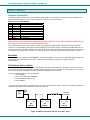
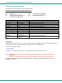
NTI
R
1275 Danner Dr Tel:330-562-7070
NETWORK
TECHNOLOGIES Aurora, OH 44202 Fax:330-562-1999
INCORPORATED www.networktechinc.com
NODEMUX ® Series
ST-nXm-U
Multi-user Universal KVM Switch
Installation and Operation Manual
Software Version 1.34
MAN044
Rev Date 3/9/2007
TRADEMARK
NODEMUX is a registered trademark of Network Technologies Inc in the U.S. and other countries.
COPYRIGHT
Copyright © 2000-2007 by Network Technologies Inc. All rights reserved. No part of this publication may be reproduced, stored
in a retrieval system, or transmitted, in any form or by any means, electronic, mechanical, photocopying, recording, or otherwise,
without the prior written consent of Network Technologies Inc, 1275 Danner Drive, Aurora, Ohio 44202.
CHANGES
The material in this guide is for information only and is subject to change without notice. Network Technologies Inc reserves the
right to make changes in the product design without reservation and without notification to its users.
i
MAN044
Rev Date 3/9/2007
TABLE OF CONTENTS
INTRODUCTION............................................................................................................................................................. 1
Features....................................................................................................................................................................... 1
Compatibility ................................................................................................................................................................ 1
Ordering Information.................................................................................................................................................... 3
ST-nXm-U Switch ..................................................................................................................................................... 3
Materials ................................................................................................................................................................... 3
Interface Cables........................................................................................................................................................ 4
FEATURES AND FUNCTIONS ...................................................................................................................................... 5
RACK MOUNTING INSTRUCTIONS ............................................................................................................................. 6
INSTALLATION & CONFIGURATION........................................................................................................................... 7
Cable Selection Guide For CPU and Keyboard/Mouse ............................................................................................ 10
USING THE NTI NODEMUX UNIVERSAL KVM SWITCH .......................................................................................... 11
Basic Operation ......................................................................................................................................................... 11
Keypad Control .......................................................................................................................................................... 11
OSD Control .............................................................................................................................................................. 12
Security Option with Password ............................................................................................................................... 12
Enabling The Security Feature ............................................................................................................................... 12
Password and User Name ................................................................................................................................ 12
OSD Modes Available With Security Enabled ........................................................................................................... 13
User Login............................................................................................................................................................... 13
Administration ......................................................................................................................................................... 13
Port Status .............................................................................................................................................................. 14
Administration Options............................................................................................................................................ 14
User Name List ....................................................................................................................................................... 15
System Access List................................................................................................................................................. 15
User Access Functions .............................................................................................................................................. 16
Command Mode ..................................................................................................................................................... 16
Edit Mode................................................................................................................................................................ 17
Search Mode........................................................................................................................................................... 18
Maintenance Mode ................................................................................................................................................. 18
Help Mode............................................................................................................................................................... 19
SUN DDC Configuration ............................................................................................................................................ 19
RS232 CONTROL......................................................................................................................................................... 20
Remote Connection ................................................................................................................................................... 20
Baud Rate ............................................................................................................................................................... 20
Unit Address and Loop Back .................................................................................................................................. 20
RS-232 Command Protocol....................................................................................................................................... 22
RS-232 Command Protocol Quick Reference........................................................................................................ 22
Autostatus .......................................................................................................................................................... 22
Matrix Switcher's Control Program For Windows 9X, NT, 2000 and XP................................................................... 23
SerTest- RS232 Interface Test Program ................................................................................................................... 24
Main Options........................................................................................................................................................ 24
Matrix Operations ................................................................................................................................................ 24
Setup Options ...................................................................................................................................................... 25
RMTEST-RS232 Interface Test Program.................................................................................................................. 25
Main Options........................................................................................................................................................... 25
Matrix Options......................................................................................................................................................... 25
Setup Options ......................................................................................................................................................... 25
KEYBOARD MAPPING ................................................................................................................................................ 26
Key Equivalents ......................................................................................................................................................... 26
SUN's Startup Keys ................................................................................................................................................... 26
TROUBLESHOOTING.................................................................................................................................................. 28
SPECIFICATIONS ........................................................................................................................................................ 28
INDEX............................................................................................................................................................................ 29
WARRANTY INFORMATION ....................................................................................................................................... 29
ii
MAN044
Rev Date 3/9/2007
TABLE OF FIGURES
Figure 1- Mount the NODEMUX to a rack....................................................................................................................... 6
Figure 2- Connect monitor to NODEMUX ....................................................................................................................... 7
Figure 3- Connect PS/2 devices to NODEMUX .............................................................................................................. 8
Figure 4- Connect PS/2 CPU to NODEMUX................................................................................................................... 9
Figure 5- Cable Selection Guide ................................................................................................................................... 10
Figure 6- Login screen .................................................................................................................................................. 12
Figure 7- Administration Mode ...................................................................................................................................... 13
Figure 8- Port Status for Port 1 ..................................................................................................................................... 14
Figure 9- Administration Options menu......................................................................................................................... 14
Figure 10- User Name List ............................................................................................................................................ 15
Figure 11- System Access List...................................................................................................................................... 15
Figure 12- Command Mode main menu ....................................................................................................................... 16
Figure 13- Maintenance Mode menu ............................................................................................................................ 19
Figure 14- RS232 connection with "IN" and "OUT" ports.............................................................................................. 20
Figure 15- RS232 connection with Matrix-Y-1 cable..................................................................................................... 21
Figure 16- Matrix-Y-1 wiring schematic......................................................................................................................... 21
Figure 17- Keyboard key layouts .................................................................................................................................. 27
iii
MAN044
Rev Date 3/9/2007
NTI NODEMUX MULTI-USER UNIVERSAL KVM SWITCH
INTRODUCTION
The NTI ST-nXm-U (NODEMUX) is a multi-user / universal KVM switch, (n= number of users, m= number of CPUs). It allows
multiple users, up to 8, each with a keyboard, monitor, and mouse, to communicate directly with any PC or SUN workstation
connected to the switch. A single switch can connect to up to 32 CPUs. These CPUs can be file servers, network managers, etc.
The auto-boot circuitry in the NODEMUX allows all CPUs to boot simultaneously without keyboard and/or mouse error.
Features
¾
Users can work individually or share the same CPU.
¾
Up to n users can work with m CPUs where n and m are the switch size acquired.
¾
Universal input and output ports that interface cables plug into adapt to PC and SUN platform devices.
¾
Power cycle circuit control allows the NTI switch to be powered OFF, then ON, at any time without affecting the attached
CPUs.
¾
Power cycle circuit control allows the attached CPUs to be powered OFF, then ON, at any time without affecting the switch or
other attached CPU.
¾
OSD enabled system with security features optionally enabled on a port by port basis.
¾
A microprocessor is dedicated to each CPU, preventing connected CPUs from locking up.
¾
Each connected CPU can boot without a keyboard or mouse.
¾
Keyboard and mouse interface cable can be hot-plugged during operation.
¾
LCD display on the front panel shows the CPU to which each user is connected.
¾
10 connection setups can be saved in memory by the user for instant setup recall.
¾
No dip switches or jumpers necessary to configure.
¾
Video formats up to 1900X1200 can be displayed from all platforms. (A VGA multi-scan monitor must be used)
¾
User’s keyboard and mouse can control the switch using the On Screen Display (OSD) of each user’s connections
¾
Names can be assigned to the CPUs
¾
Password security on a PORT enabled basis.
¾
RS-232 control allows control of the switch with one CPU serial port.
¾
Power required is 110 or 220 VAC @ 50-60 Hz at less than 25 watts.
Compatibility
Supported CPUs:
•
All PS/2 style PCs
•
PS/2 laptops
•
IBM RS6000
•
Silicon Graphics
•
HP9000
•
Supports SUN, including ULTRAs™, SUN Blade™ 100, SUN Blade 1000, SUN Fire™ 280R, SUN Fire V20z and SUN
Ray™ (using NTI’s USB-SUN adapter).
Supported Mice:
•
Compatible with all standard 2-button PS/2 mice as well as the following:
•
Microsoft IntelliMouse®
•
Logitech (and other) 3-button mice.
•
Alps glidepoint touchpad (extended functions-i.e. tapping, etc.-are not supported).
•
Cirque Glidepoint touchapd.
•
IBM Scroll Point mouse (extended stick functions are not supported).
•
Kensington Orbit trackball.
•
Logitech 2-button wheel mouse.
•
Microsoft Ballpoint mouse.
•
SUN 3-button mice are supported. Wheel button on IntelliMouse emulates SUN's third mouse button.
1
NTI NODEMUX MULTI-USER UNIVERSAL KVM SWITCH
Supported Keyboards
•
User devices can be PS/2 or SUN.
•
SUN startup keys are supported on all platforms of input devices.
•
Keystrokes are translated across platforms.
•
Keyboard is hot-pluggable.
•
Internet and Windows key supported.
Supported Monitors:
•
Multiscan SVGA, XGA, and VGA monitors
See our catalog, visit our website at www.networktechinc.com, or contact an NTI sales representative at 800-742-8324 (800-RGBTECH) or 330-562-7070 for more details.
2
NTI NODEMUX MULTI-USER UNIVERSAL KVM SWITCH
Ordering Information
ST-nXm-U Switch
The ST-nXm-U switch is built to a specific size ranging from 2 to 8 users and 8 to 32 CPUs. The switch is built at the factory
based on the specified size ordered. The switch has universal inputs and outputs that support all platforms and are configured
with interface cables (see " Interface Cables" below). The “n” in the part number ST-nXm-U represents the number of users.
Select either 2 ,4, or 8 user switches. The “m” in the part number represents the number of CPUs. The switch is available with
support for either 8 , 16,or 32 CPUs. It is not necessary to connect a user or CPU to each port (ex. a ST-2x16 switch has the
capability of supporting 16 CPUs, but can have only 10 CPUs connected and 6 empty ports.
ST-nXm-U
Replace the “n” with either 2,4, or 8
Replace the “m” with either 8,16, 24, or 32
The following list represents the available sizes that can be ordered:
ST-2X2-U*
ST-4X8-U*
ST8X8-U
ST-2X4-U*
ST-4X16-U
ST8X16-U
ST-2x8-U*
ST-4X32-U
ST8X24-U
ST-2x16-U
ST8X32-U
ST-2X32-U
*This size is also available in a desktop style case instead of a rack mount case- just add "DT" when ordering
Materials
Materials Supplied with this kit include:
•
•
•
•
•
NTI ST-nXm-U Multi-user Universal KVM Switch
Power cord- country specific
120 or 240VAC at 50 or 60Hz-5VDC/4A AC Adapter (models ST-2X2-UDT, ST-2X4-UDT, ST-2X8-UDT, and ST-4X8-UDT
only)
8-#10-32 x 3/4" pan head screws and #10-32 cagenuts (server cabinet mounting hardware)
CD with pdf file of this manual
3
NTI NODEMUX MULTI-USER UNIVERSAL KVM SWITCH
Interface Cables
Interface cables are not included and must be purchased separately.
A set of 2 cables for each CPU being connected to the switch:
PS/2 CPU to Switch
VEXT-xx-MM for video interface
VKTINT-xx-MM for keyboard and mouse interface
OR
SUN CPU to Switch
VEXT-xx-MM for video interface
13W3M-15HDF (adapter for 13W3 to 15HD)
SKTINT-xx-MM for keyboard/mouse interface
One of the following cables must be used to connect the keyboard/mouse:
PS/2 keyboard/mouse
VKTINT-1
OR
SUN keyboard/mouse
None needed. SUN keyboard plugs directly in.
where:
xx is the length of the cable in feet
MM indicates male-to-male connector, and
MF indicates male-to-female connector.
See also, page 10, for Cable Selection Guide.
Cables can be purchased from Network Technologies Inc by calling 800-RGB-TECH (800-742-8324) or (330)-562-7070 or by
visiting our website at www.networktechinc.com.
Custom cable lengths are available – contact NTI for pricing and distance / resolution limitations.
4
NTI NODEMUX MULTI-USER UNIVERSAL KVM SWITCH
2
1
NODEMUX TM
NTI
R
ESC
USR
6
7
8
9
0
*
MENU
CPU
1
2
3
4
5
ENTER
Network Technologies Inc
DDC
Front View of NODEMUX
FEATURES AND FUNCTIONS
1.
Keypad- buttons for user control over switch functions
2.
LCD Display- for visual indication of connection between the user and a specific CPU.
3.
CPU x- 8 pin miniDIN female connectors- for connection of CPU device cables
4.
User x- 8 pin miniDIN female connectors- for connection of user device cables
5.
Power switch- for powering the NODEMUX On/Off
6.
IEC Power Connector- for attachment of power cord (not available on all units)
7.
Fuse Holder- holder for replaceable 2A 240VAC overcurrent protection fuse (not available on all units)
8.
RS232- for attaching RS232 interface cable from a CPU to control the functions of one or more switches
9.
MONITOR x- 15HD female connectors- for connection of user monitors
10. VIDEO x- 15HD female connectors- for attachment of video cables from CPUs
3
4
Rear View of NODEMUX
USER 4
USER 3 USER 2
USER 1
NTI
R NETWORK
1275 Danner Dr
Tel:330-562-7070
TECHNOLOGIES
INCORPORATED Aurora, OH 44202 Fax:330-562-1999
www.nti1.com
CPU 16 CPU 15 CPU 14 CPU 13 CPU 12 CPU 11 CPU 10 CPU 9
R
S
2
3
2
5 6 7
CPU 8
CPU 7
CPU 6
CPU 5
CPU 4
CPU 3
CPU 2
CPU 1
MONITOR 3
MONITOR 1
VIDEO 15
VIDEO 13
VIDEO 11
VIDEO 9
VIDEO 7
VIDEO 5
VIDEO 3
VIDEO 1
MONITOR 4
MONITOR 2
VIDEO 16
VIDEO 14
VIDEO 12
VIDEO 10
VIDEO 8
VIDEO 6
VIDEO 4
VIDEO 2
8
9
10
5
NTI NODEMUX MULTI-USER UNIVERSAL KVM SWITCH
RACK MOUNTING INSTRUCTIONS
This NTI switch was designed to be directly mounted to a rack. It includes a mounting flange to make attachment easy.
Install 4 cage nuts (supplied) to the rack in locations that line up with the holes (or slots) in the mounting flange on the NTI switch.
Then secure the NTI switch to the rack using four #10-32 screws (supplied). Be sure to tighten all mounting screws securely.
Note: Do not block power supply vents in the NTI switch chassis (if provided).
front of and behind the NTI switch.
Be sure to allow for adequate airflow in
Attach all cables securely to the switch and where necessary supply adequate means of strain relief for cables.
Rack
Cage Nuts
(supplied)
10-32
Rack Screws
(supplied)
Figure 1- Mount the NODEMUX to a rack
6
NTI NODEMUX MULTI-USER UNIVERSAL KVM SWITCH
INSTALLATION & CONFIGURATION
Power OFF all CPUs that will be connected to the NTI Switch before connecting or disconnecting any cables.
WARNING! CPUs may be damaged if cables are connected or disconnected while power is ON.
1.
Connect the monitors to the ports labeled "MONITOR x" on the rear of the NODEMUX.
Rear View of NODEMUX
USER 4
USER 3 USER 2
NTI
USER 1
R NETWORK
TECHNOLOGIES
INCORPORATED
1275 Danner Dr Tel:330-562-7070
Aurora, OH 44202 Fax:330-562-1999
www.nti1.com
CPU 16 CPU 15 CPU 14 CPU 13 CPU 12 CPU 11 CPU 10
R
S
2
3
2
CPU 9
CPU 8
CPU 7
CPU 6
CPU 5
CPU 4
CPU 3
CPU 2
CPU 1
MONITOR 3
MONITOR 1
VIDEO 15
VIDEO 13
VIDEO 11
VIDEO 9
VIDEO 7
VIDEO 5
VIDEO 3
VIDEO 1
MONITOR 4
MONITOR 2
VIDEO 16
VIDEO 14
VIDEO 12
VIDEO 10
VIDEO 8
VIDEO 6
VIDEO 4
VIDEO 2
MONITOR 1
15HD Male
Video Connector
15HD Female
Video Connector
VGA
Multi-Scan
Monitor
Figure 2- Connect monitor to NODEMUX
7
NTI NODEMUX MULTI-USER UNIVERSAL KVM SWITCH
2.
Connect the keyboards to the ports labeled "USER x" on the rear of the NTI Switch. (See Figure 3) Use the proper interface
cables. (See also Cable Selection Guide on page 10.) Insure that the monitors and related keyboards have the same port
numbers.
FYI: If it is desired for only a monitor to be connected to a set of user ports, an NTI keyboard cable (VKTINT-1 for
example) must also be connected to the keyboard port for that user. (The other end of the VKTINT-1 does not need to be
connected to anything.) This is required in order to enable the user of that port to switch between CPU ports on the NTI
Universal KVM switch. (See Figure 5- Cable Selection Guide on page 10 "Video-Only User".)
Rear View of NODEMUX
USER 4
USER 3 USER 2
USER 1
NTI
R NETWORK
TECHNOLOGIES
INCORPORATED
1275 Danner Dr Tel:330-562-7070
Aurora, OH 44202 Fax:330-562-1999
www.nti1.com
CPU 16 CPU 15 CPU 14 CPU 13 CPU 12 CPU 11 CPU 10
R
S
2
3
2
CPU 9
CPU 8
CPU 7
CPU 6
CPU 5
CPU 4
CPU 3
CPU 2
CPU 1
MONITOR 3
MONITOR 1
VIDEO 15
VIDEO 13
VIDEO 11
VIDEO 9
VIDEO 7
VIDEO 5
VIDEO 3
VIDEO 1
MONITOR 4
MONITOR 2
VIDEO 16
VIDEO 14
VIDEO 12
VIDEO 10
VIDEO 8
VIDEO 6
VIDEO 4
VIDEO 2
8 miniDIN
Male Connector
6mD Female
Connectors
Purple- Keyboard
VKTINT-1
Green- Mouse
PS/2 MOUSE
PS/2 KEYBOARD
Figure 3- Connect PS/2 devices to NODEMUX
3.
For each CPU: Connect a cable from the Keyboard port of the CPU to a port labeled "CPU x" on the NODEMUX. (See
Figure 4 on page 9 and Cable Selection Guide on page 10.) Note the port’s number.
8
NTI NODEMUX MULTI-USER UNIVERSAL KVM SWITCH
4.
Connect a VEXT-xx-MM (and adapter if needed) from the video port of the CPU to a port labeled "VIDEO x" on the
NODEMUX with the same port number as the keyboard. Make sure the CPU is connected to a "CPU x" port and a "VIDEO x"
port with the same number. Otherwise the user's typing may be going to one CPU, but the user will be viewing a different
CPU on the monitor.
8 miniDIN
Female Connector
CPU 1
Rear View of NODEMUX
USER 4
USER 3 USER 2
USER 1
NTI
R NETWORK
TECHNOLOGIES
INCORPORATED
1275 Danner Dr Tel:330-562-7070
Aurora, OH 44202 Fax:330-562-1999
www.nti1.com
CPU 16 CPU 15 CPU 14 CPU 13 CPU 12 CPU 11 CPU 10
R
S
2
3
2
CPU 9
CPU 8
CPU 7
CPU 6
CPU 5
CPU 4
CPU 3
CPU 2
CPU 1
MONITOR 3
MONITOR 1
VIDEO 15
VIDEO 13
VIDEO 11
VIDEO 9
VIDEO 7
VIDEO 5
VIDEO 3
VIDEO 1
MONITOR 4
MONITOR 2
VIDEO 16
VIDEO 14
VIDEO 12
VIDEO 10
VIDEO 8
VIDEO 6
VIDEO 4
VIDEO 2
VIDEO 1
Rear View of PS/2 CPU
6mD Male
Connectors
15HD Female
Video Connector
8 miniDIN
Male Connector
Input Device Ports
Beige
Purple- Keyboard
VKTINT-xx-MM
Green- Mouse
6 miniDIN Female
Video Port
VEXT-xx-MM
15HD Female
Video Connector
15HD Male
Video Connector
Figure 4- Connect PS/2 CPU to NODEMUX
5. Plug the NTI Switch into an AC power outlet.
6. Turn ON power to the NTI Switch, the LCD should illuminate.
7. Turn ON power to any or all CPUs connected to the NTI Switch.
FYI: The order in which the CPUs and switch are turned ON does not matter. A power strip can be used.
9
NTI NODEMUX MULTI-USER UNIVERSAL KVM SWITCH
Cable Selection Guide For CPU and Keyboard/Mouse
existing mouse
existing keyboard
VKTINT-1
existing Keyboard cable
VKTINT-xx-MM
USER 4
USER 3 USER 2
NTI
USER 1
USER 4
R NETWORK
1275 Dan ner Dr
Tel :330-562-7070
TECHNOLOGIES Auro ra, OH 44202 Fax:330-562-1999
INCORPORATED
USER 3 USER 2
NTI
USER 1
www .nti 1.com
CPU 16 CPU 15 CPU 14 CPU 13 CPU 12 CPU 11 CPU 10
CPU 9
CPU 8
CPU 7
CPU 6
CPU 5
CPU 4
CPU 3
CPU 2
R NETWORK
1275 Dan ner Dr
Tel :330-562-7070
TECHNOLOGIES Auro ra, OH 44202 Fax:330-562-1999
INCORPORATED
www .nti 1.com
CPU 16 CPU 15 CPU 14 CPU 13 CPU 12 CPU 11 CPU 10
CPU 1
CPU 9
CPU 8
CPU 7
CPU 6
CPU 5
CPU 4
CPU 3
CPU 2
CPU 1
USER 4
USER 3 USER 2
NTI
USER 1
R NETWORK
1275 Dan ner Dr
Tel :330-562-7070
TECHNOLOGIES Auro ra, OH 44202 Fax:330-562-1999
INCORPORATED
www .nti 1.com
CPU 16 CPU 15 CPU 14 CPU 13 CPU 12 CPU 11 CPU 10
MONIT OR 3
R
S
2
3
2
MONIT OR 4
MONIT OR 1
VIDEO 15
MONIT OR 2
VIDEO 13
VIDEO 16
VIDEO 11
VIDEO 14
VIDEO 9
VIDEO 12
VIDEO 7
VIDEO 10
VIDEO 5
VIDEO 8
VIDEO 3
VIDEO 6
VIDEO 1
VIDEO 4
VIDEO 2
R
S
2
3
2
MONIT OR 3
MONIT OR 1
VIDEO 15
VIDEO 13
VIDEO 11
VIDEO 9
VIDEO 7
VIDEO 5
VIDEO 3
VIDEO 1
MONIT OR 4
MONIT OR 2
VIDEO 16
VIDEO 14
VIDEO 12
VIDEO 10
VIDEO 8
VIDEO 6
VIDEO 4
VIDEO 2
R
S
2
3
2
VGA
Multi-Scan
Monitor
CPU 8
CPU 7
CPU 6
CPU 5
CPU 4
CPU 3
CPU 2
CPU 1
MONIT OR 1
VIDEO 15
VIDEO 13
VIDEO 11
VIDEO 9
VIDEO 7
VIDEO 5
VIDEO 3
VIDEO 1
MONIT OR 4
MONIT OR 2
VIDEO 16
VIDEO 14
VIDEO 12
VIDEO 10
VIDEO 8
VIDEO 6
VIDEO 4
VIDEO 2
existing
monitor
cable
existing
monitor
cable
CPU 9
MONIT OR 3
VEXT-xx-MM
VGA
Multi-Scan
Monitor
Mouse
Keyboard
PC
PS/2 Keyboard & Mouse
SUN Keyboard & Mouse
VKTINT-1 (A keyboard cable is still required)
(no mouse)
(no keyboard)
USER 4
USER 3 USER 2
USER 1
NTI
R NETWORK
1275 Dan ner Dr
Tel :330-562-7070
TECHNOLOGIES Auro ra, OH 44202 Fax:330-562-1999
INCORPORATED
CPU 16 CPU 15 CPU 14 CPU 13 CPU 12 CPU 11 CPU 10 CPU 9
MONIT OR 3
R
S
2
3
2
MONIT OR 4
MONIT OR 1
MONIT OR 2
VIDEO 15
VIDEO 16
VIDEO 13
VIDEO 14
VIDEO 11
VIDEO 12
CPU 8
VIDEO 9
VIDEO 10
CPU 7
CPU 6
VIDEO 7
VIDEO 8
CPU 5
CPU 4
VIDEO 5
VIDEO 6
CPU 3
CPU 2
VIDEO 3
VIDEO 4
USER 3 USER 2
USER 1
CPU 1
NTI
USER 4
R NETWORK
1275 Dan ner Dr
Tel :330-562-7070
TECHNOLOGIES Auro ra, OH 44202 Fax:330-562-1999
INCORPORATED
MONIT OR 3
R
S
2
3
2
MONIT OR 4
MONIT OR 1
MONIT OR 2
VIDEO 15
VIDEO 16
VIDEO 13
VIDEO 14
VIDEO 11
VIDEO 12
existing
monitor
cable
VGA
Multi-Scan
Monitor
USER 3 USER 2
USER 1
www .nti 1.com
CPU 16 CPU 15 CPU 14 CPU 13 CPU 12 CPU 11 CPU 10
VIDEO 1
VIDEO 2
VKTINT-xx-MM
SKTINT-xx-MM
USER 4
www .nti 1.com
CPU 9
CPU 8
VIDEO 9
VIDEO 10
CPU 7
CPU 6
VIDEO 7
VIDEO 8
CPU 5
CPU 4
VIDEO 5
VIDEO 6
CPU 3
CPU 2
VIDEO 3
VIDEO 4
VIDEO 1
VEXT-xx-MM
13W3M-15HDF
Adapter
R NETWORK
1275 Dan ner Dr
Tel :330-562-7070
TECHNOLOGIES
INCORPORATED Auro ra, OH 44202 Fax:330-562-1999
www .nti 1.com
CPU 16 CPU 15 CPU 14 CPU 13 CPU 12 CPU 11 CPU 10 CPU 9
CPU 1
VIDEO 2
NTI
R
S
2
3
2
CPU 8
CPU 7
CPU 4
CPU 3
CPU 2
CPU 1
VIDEO 15
VIDEO 13
VIDEO 11
VIDEO 9
VIDEO 7
VIDEO 5
VIDEO 3
VIDEO 1
MONIT OR 4
MONIT OR 2
VIDEO 16
VIDEO 14
VIDEO 12
VIDEO 10
VIDEO 8
VIDEO 6
VIDEO 4
VIDEO 2
VEXT-xx-MM
"Y" Adapter
(supplied by PC
Manufacturer)
Video-Only User
Laptop PC
10
CPU 5
MONIT OR 1
SUN WORKSTATION
Figure 5- Cable Selection Guide
CPU 6
MONIT OR 3
NTI NODEMUX MULTI-USER UNIVERSAL KVM SWITCH
USING THE NTI NODEMUX UNIVERSAL KVM SWITCH
Basic Operation
The NODEMUX enables a user or several users to access any CPU at any time. Users can even share a CPU and work on the
same project – each from their own console. Resolution is supported through 1900x1200 with no degradation – guaranteed. A
Liquid Crystal Display (LCD) on the front panel indicates the port to which the user is attached. The NODEMUX can be controlled
by three methods;
•
•
•
keypad control with LCD via front panel
OSD control via the user devices
RS-232 control (see page 20)
Keypad Control
The front panel keypad and LCD display allow the user to monitor switch status and route any user to any CPU on the switch.
Along with the routing of the inputs to the outputs the keypad and LCD allow the users to configure the RS-232 control interface.
The keypad buttons perform the following functions:
Key
Action
ESC
Cancel current action. Escape back to the main display.
0–9
Used to enter numbers. ( n )
USR
The user device number can be entered (2 digits or 1 digit and ENTER) followed by the desired
CPU to be connected to (2 digits or 1 digit and ENTER).
CPU
Used following single digit user entries.
ENTER
Used to enter commands or values.
Up Arrow
Display next 4 users and the CPUs they are connected to. (See note below.)
Down Arrow
Display previous 4 users and the CPUs they are connected to. (See note below.)
MENU
The Configuration Menu is displayed. See RS-232 control.
*
Activate Memory Function- 10 memory locations (0 – 9), 0 is the power ON default.
- to Save current connections
- to Recall connections
* - USR - n (0-9) - ENTER
* - CPU - n (0-9) – ENTER
The following examples show various methods of routing user 3 to CPU 5. Users and CPUs can be entered as a two digit number
or a one digit number followed by ENTER.
USR - 3 - CPU - 5 - ENTER
USR - 3 - ENTER - 5 - ENTER
CPU:
USR:
1
1
2
2
3
3
4
4
ESC
USR
7
8
9
MENU
CPU
4
5
6
*
0
1
2
3
USR - 0 - 3 - 0 - 5
0-3-0-5
ENTER
Note: By default, the display will show all connections between CPUs and users, displaying 4 at a time, from the first to
the last, and repeating the cycle indefinitely. If the user presses either the up or down arrow to manually view
connections, the display will freeze on the chosen view. To resume the default cycle of displaying all connections, the
user must press and hold either the up or down arrow for 3 seconds, and then release it.
11
NTI NODEMUX MULTI-USER UNIVERSAL KVM SWITCH
OSD Control
OSD superimposes a menu system on the user’s video screen with a list of all connected CPUs. OSD allows CPUs to be named
(with up to 12 character names). OSD then allows selection of CPUs by that name. Connected CPUs can be listed by name or
by port number. OSD Search Mode enables the user to type in the first few characters of the CPU's name and the OSD will
locate it. HELP screens assist with all OSD functions.
Security Option with Password
The security option in the OSD Control of the NODEMUX switch enables an administrator to control access to CPU ports for each
user. Up to 63 users can be created. These users have controlled access to any CPU. Only the administrator can activate or
deactivate the security features on each user port. Finally, the administrator can set a maximum idle time value after which the
current user will be logged out and the login screen displayed again. This time out does not function while the OSD is active. The
current security status, idle time out, and scan dwell time are all saved and will be restored whenever power to the switch is cycled
OFF, then ON. To reset the administrator’s password call NTI and have the device serial number of the NODEMUX switch
available.
Enabling The Security Feature
To enable the security feature the administrator must first enter Command Mode from the keyboard using the <Ctrl> + <`> (accent
key). The OSD menu will automatically appear on the monitor. This provides a visual way to control the NODEMUX switch using
the keyboard and mouse.
The administrator , when setting the Universal KVM switch up for the first time, may want to proceed directly to the
ADMINISTRATION Mode by typing <CTRL> + <M> , then <A>, and then <Y>.
Password and User Name
The factory default settings are:
• user name = ADMINISTRATOR
• password = ADMINISTRATOR
Figure 6- Login screen
Note: The username for the administrator cannot be changed from "ADMINISTRATOR".
Once logged-in, follow the instructions on page 14 for setting up users and changing the administrator password. Once the
password is setup, if it is lost or forgotten, the administrator will have to contact NTI for assistance on clearing the password and
set it up again. Within the ADMINISTRATION Mode the administrator can setup each of the users and the limitations of their use
of the individual CPUs on the system.
When a standard user powers up the system a security screen may appear as setup by the administrator. The user will
need to login to the system by following the instructions below for the USER LOGIN. If the user does not know the appropriate
user name and password (setup by the administrator), contact the system administrator for this information. Once logged-in a
user can follow the Command Functions described on page 16 to control the system of CPUs within the limitations as determined
by the administrator.
12
NTI NODEMUX MULTI-USER UNIVERSAL KVM SWITCH
OSD Modes Available With Security Enabled
User Login
User login mode requires a user to login with a user name and password from the list created by the Administrator.
Key
Alphanumeric
Backspace
Enter
Esc
Function
Adds a character to the user name/password.
Removes previous character from the user name/password
Submit user name/password
Exit USER LOGIN and return to previous mode. This function is only available if security is
not currently active.
The Administration, Port Status, Administration Options, User Name List, and System Access List modes are only available if the
following conditions are met:
1. The security feature has been enabled
2. The administrator is currently logged in
Administration
Administration mode (press <A> from the Maintenance Mode menu) allows the administrator to select a port for extended status
information, or choose one of the following options:
Key
A
Enter
Esc
Function
Enter Administration Options mode
Enter Port Status mode for selected port
Exit ADMINISTRATION and return to previous mode
Figure 7- Administration Mode
The mouse can be used to control administration mode as well as the keyboard. Ports can be selected that are on the screen by
moving the cursor onto that port and clicking. Clicking twice on a selected port will switch to that port and exit command mode.
To change the displayed ports on the screen click on the up and down arrows that are located to the right of the port names
displayed.
13
NTI NODEMUX MULTI-USER UNIVERSAL KVM SWITCH
Port Status
Port status mode (press <Enter> from Administration mode menu) allows the administrator to view extended status information
about the port selected in Administration mode. The information available here can also be found on the main COMMAND menu,
except when multiple users are connected to a single CPU. In that event, while the main COMMAND menu simply lists the
number of users connected, the specific users connected can be seen here.
Key
Esc
Function
Exit PORT STATUS and return to previous mode
Figure 8- Port Status for Port 1
Administration Options
Administration Options mode (press <A> from Administration mode menu) allows the Administrator to use the following functions:
Key
C
S
U
P
Txxx
Esc
Function
Change the Administrator’s password
Disable security
Enter User Name List mode
Disable/enable sharing
Selects the idle time in minutes. xxx= time in minutes from 1(001) to 255. Use 000 to disable this feature.
Exit ADMINISTRATION OPTIONS and return to previous mode
Figure 9- Administration Options menu
14
NTI NODEMUX MULTI-USER UNIVERSAL KVM SWITCH
User Name List
The User name list (press <U> from the Administration Options menu) displays the list of users and provides control for adding
new users, changing or assigning user passwords, and changing access rights for any given user. The user names have a
maximum size of 12 characters, may not include spaces, and are not case sensitive. The passwords have a maximum size of 15
characters, may not include spaces, and are case sensitive.
Key/Sequence
Ctrl-A
Ctrl-E
Ctrl-P
Esc
Function
Edit the highlighted user’s access rights
Enter Edit mode to add/change/remove users
Change the highlighted user’s password
Exit the User name list and return to previous mode
Figure 10- User Name List
System Access List
The System access list (press <Ctrl> - <A> from the User Name List) displays the ports so that the Administrator can change
access rights for the selected user. That user’s name is displayed at the top of the access list.
Figure 11- System Access List
15
NTI NODEMUX MULTI-USER UNIVERSAL KVM SWITCH
User Access Functions
Command Mode
In order to control the switch with the keyboard, Command Mode must be enabled. To enable Command Mode from the
keyboard:
Press
Ctrl + ` (Accent key)
All the status lights on the keyboard will illuminate to indicate that Command Mode is enabled. At this point, the Command Mode
menu will be displayed.
The Command Mode menu lists all CPUs by name and port number. Only 8 ports are listed on the screen at a time. To view the
other portions of the list, scroll using the arrow keys on the keyboard or use the mouse to click on the arrows on the scroll bar in
the OSD menu. When the Command Mode main menu is displayed, the first displayed port in the list will be the port the current
user is connected to, followed by the next seven consecutively numbered ports. (Alternatively the list may be sorted
alphabetically- see Maintenance Mode on page 18 to toggle sort method.) The names of accessible ports are displayed with
white characters. If Security is activated, the access rights for the user logged-in may not include all ports. Names of restricted
access ports are displayed in blue.
Type of CPU
Power
Status
User Number
Port Number
Port Name
Scroll Bar
Figure 12- Command Mode main menu
From left to right, the columns display the following:
•
Port Number
•
Port Name
•
Type of CPU connected (PS2 or SUN)
•
Power status of that CPU (ON/OFF)
•
User number (1-8) connected to that CPU
At the far right, arrows pointing up and down allow for mouse clicking to maneuver up and down through the menu. While in
COMMAND Mode, the numbers on the NUM PAD are not active. If numbers are required while in COMMAND Mode, use the
numbers on the main key bank.
When the COMMAND LED is illuminated, the following functions are available with the OSD:
Key/Sequence
Function
↑
Select previous port on OSD display
↓
Select next port on OSD display
Page Up
Increments the menu by 1 page
Page Down
Decrements the menu by 1 page
Ctrl-E
Enter Edit mode
Ctrl-M
Enter Maintenance mode
16
NTI NODEMUX MULTI-USER UNIVERSAL KVM SWITCH
COMMAND MODE FUNCTIONS (Cont'd)
Key/Sequence
Function
Ctrl-S
Scan Mode enable/disable (to begin scanning, simply exit COMMAND Mode after enabling
the function – Scroll Lock status light will blink when scanning)
F1
Display HELP menu (available within every control mode)
Ctrl-P-x-x
Selects a specific port. xx = port number as a two digit number (ex. p01, p08, p15, etc.)
Ctrl-T-x-x-x
Selects the scan time in seconds. xxx = time in seconds between 2 (002) and 255
Home
Selects the first port on the switch
End
Selects the last port on the switch
Alphanumeric
Typing any alphanumeric enters Search Mode and adds a character to search string and
selects the CPU’s name that matches best
Enter
Switch to a selected port
Esc
Exit keyboard command mode
The mouse can be used to control command mode as well as the keyboard. The mouse cursor can be moved to the Help and
Exit fields, which can be then clicked on to perform that function. The port that is on the screen can be selected by moving the
cursor onto that port and clicking. Clicking twice on a selected port will switch to that port and exit COMMAND Mode. To change
the displayed ports on the screen click on the up and down arrows that are located to the right of the port names displayed.
Note: Exit COMMAND Mode to type to a CPU. To exit COMMAND Mode, press <Esc>, or press <Ctrl> + <` >(accent) keys
simultaneously or by clicking the “ESC” command on the screen with the mouse.
Note: When in SCAN Mode, stop the SCAN cycle temporarily by typing or moving the mouse. That CPU will remain
selected on that port as long as there is typing or mouse movement. SCAN will continue after all keyboard or mouse
activity ceases and the configured scan time (from chart above) expires.
Edit Mode
Edit mode (press <Ctrl> - <E> from Command Mode menu) allows the user to modify the names of the CPUs connected to the
switch. Names of CPUs can be up to 12 characters in length. When in Edit mode, multiple keystroke combinations are not valid
(<SHIFT>+<P>, <CTRL>+<P>, <ALT>+<P>, and <P> will all type a “P” to the display - lower case letters cannot be typed). After
changes have been made, answer the question asked. Answer "Y" to save changes and answer "N" to continue using previously
entered port names. The <Esc> key will exit EDIT Mode and abort any EDIT session.
Key/Sequence
Function
→
Move cursor one position to the right
←
Move cursor one position to the left
↑
Previous port on OSD display
↓
Next port on OSD display
Home
Selects the first port on the switch
End
Selects the last port on the switch
Insert
Toggles between insert (character gets inserted and the remainder of the name gets shifted to the right)
and overstrike (current character gets overwritten)
Delete
Erase current character
Backspace
Erase previous character
17
NTI NODEMUX MULTI-USER UNIVERSAL KVM SWITCH
Search Mode
Search mode allows the user to enter and maneuver through a list of CPU names. The best matching CPU name is selected. The
list of CPUs may also be searched for a specific (or similar) name. To enter SEARCH Mode, simply begin typing alphanumeric
characters. The following commands are valid when the search option has been invoked from Command mode.
Key
Function
Backspace
Erase previous character in search name
↑
Select previous port on OSD display
↓
Select next port on OSD display
Alphanumeric
Add a character to the search string and select the best matching CPU name
Esc
Exit SEARCH mode, return to COMMAND mode
Enter
Switch to selected port
Maintenance Mode
Maintenance mode (press <Ctrl> - <M> from Command Mode menu) allows a user to customize the On Screen Display to their
requirements (see Figure 13 on page 19). Also, the share feature is turned OFF or ON from Maintenance Mode. The OSD
default for sharing is ON. In this mode, any user can access any CPU at any time (even share one). When sharing is disabled,
no one but the selected user can access that CPU. When sharing is enabled, and more than one person is attached to a CPU, it
is displayed on the main COMMAND Menu. The number that displays which user is connected to which port changes color (from
white to red), and the number shows how many users are connected to that particular port. The following commands are valid
from within Maintenance mode.
Key
Function
R
Reset all of the port names
L
Toggle between numeric and alphabetic listing of ports
↑
Move On Screen Display (OSD) window up on monitor
↓
Move OSD window down on monitor
→
Move OSD window to the right
←
Move OSD window to the left
T
Make OSD window taller
S
Make OSD window Shorter
A
Activate security or Administration mode
Q
Logout ( if logon)
Enter
Save OSD window parameters for the CPU port currently connected ONLY.
Esc
Return to COMMAND mode
FYI: Based on different scan rates, the OSD window may appear in different areas of the monitor as different CPU ports
are selected. The Maintenance Mode functions allow placement of the window in a particular area of the monitor and it
will stay there when switched back to that particular CPU (as long as the parameters are saved before exiting).
18
NTI NODEMUX MULTI-USER UNIVERSAL KVM SWITCH
Figure 13- Maintenance Mode menu
Help Mode
Help mode (press <F1>) displays a list of commands with a short explanation of their function. These lists are organized in pages
for several of the operating modes (i.e. COMMAND, EDIT, SEARCH, and ADMINISTRATION). The following options allow the
user to quickly obtain information on any command.
Key
Function
Page Up
View the previous page of help if available
Page Down
View the next page of help if available
Esc
Exit HELP and return to previous mode
SUN DDC Configuration
(When connected to SUN with pgX32 or pgX64 video card)
To get a video image through the NODEMUX from a SUN CPU having the pgX32 or pgX64 video card, the SUN CPU must have
its video output configured manually. There are three ways to accomplish this:
1. Forced Resolution: Console
a. open a terminal session and su,
b. type # eeprom output-device=screen:r1024x768x70
c. REBOOT the CPU.
2. Forced Resolution: Super User
a. : Halt the machine
b. type ok setenv output-device screen:r1024x768x70
c. type ok reset2
3. Forced Resolution: Hot Plug Video
a. Unplug the monitor from the NTI switch
b. Unplug the NTI switch video cable from the CPU
c. Plug the monitor directly into the CPU
d. REBOOT the CPU
e. Unplug the monitor and reconnect to the NTI switch
f. Reconnect the NTI switch video cable to the CPU
19
NTI NODEMUX MULTI-USER UNIVERSAL KVM SWITCH
RS232 CONTROL
Remote Connection
The RS232 Interface is designed to meet the RS232C standard and can be controlled from any CPU or other controller with an
RS232 communications port. The pin outs for the DB9 connector on the unit are as follows:
RS232 Connector (DB9 FEMALE)
PIN
SIGNAL
FUNCTION
1
None
no connection
2
TXD
Transmit Data (RXD at host)
3
RXD
Receive Data (TXD at host)
4
DSR
Data Set Ready
5
GND
Signal Ground
6
DTR
Data Terminal Ready
7
CTS
Clear to Send
8
RTS
Request to Send
9
none
no connection
NOTE: Security must be disabled (see Administration Options on page 14) or user access granted (see System Access
List on page 15) on the port(s) to be selected by RS-232 control.
On the DB-9 female connector, pins 1 (DCD), 4 (DTR), and 6 (DSR) are shorted and pins 7 (RTS) and 8 (CTS) are shorted.
Therefore, CPU handshaking is bypassed and TXD and RXD are the only active signals. A straight through DB9 cable (not null
modem) will work for most CPUs. To daisy chain multiple units, the CPU drives the input port on the first unit and the output port is
connected to the input port on the next unit etc. The last unit will have a loop back plug installed in its RS232 OUT connector.
Baud Rate
The baud rate can be changed by selecting MENU on the front panel keypad. Then select 1 for SET BAUD RATE and select the
desired baud rate of 9600, 4800, 2400 or 1200. A data protocol of 8 data bits, no parity, and 1 stop bit is used for
communications.
Unit Address and Loop Back
To allow multiple units to be controlled from a single CPU port, the RS232 control interface is designed to allow "daisy chaining"
up to 15 units. By setting the appropriate unit address with the keypad, each unit can be given a unique address (1-15). Then the
unit will only respond to commands on the bus if its address is embedded in the command.
To set the unit address using the front panel keypad,
1. Press <MENU>
2. press <2> for “SET UNIT ADDRESS“
3. enter the address number (1-15)
4. press <ENTER>.
The "loop back" plug should be on the RS232 OUT connector on the last unit in the chain. If only one unit is being controlled, the
loop back plug should be on the RS232 OUT connector on that unit.
Host
CPU
RS232
Serial
Port
Loop back
Plug installed
RS232
IN
RS232
OUT
NTI
SWITCH
Unit Address 1
RS232
IN
RS232
OUT
NTI
SWITCH
Unit Address 2
RS232
IN
RS232
OUT
NTI
SWITCH
Unit Address 15
Figure 14- RS232 connection with "IN" and "OUT" ports
20
NTI NODEMUX MULTI-USER UNIVERSAL KVM SWITCH
Note: The RS232 connection on the switch may only have a single 9 pin "RS232" female connector. In this case, in
order to connect multiple NODEMUX units together, a Matrix-Y-1 cable must be used. (see Figure 15). No loop back
plug will be used with this configuration. See Figure 16 for the pinout of the Matrix-Y-1 cable.
CPU
RS232
Serial Port
Matrix-Y-1
Matrix-Y-1
Matrix-Y-1
RS232
RS232
RS232
NTI
SWITCH
NTI
SWITCH
NTI
SWITCH
First Unit
Second Unit
Last Unit
Figure 15- RS232 connection with Matrix-Y-1 cable
Wiring Schematic of Matrix-Y-1 cable
9D Male
(Unit #1)
9D Female
(Source)
9D Male
(Unit #2)
2
3
3
3
5
5
5
2
2
7
8
1
4
6
Not connected to
source connector
Jumper
Jumpers
Figure 16- Matrix-Y-1 wiring schematic
21
NTI NODEMUX MULTI-USER UNIVERSAL KVM SWITCH
RS-232 Command Protocol
Host controller commands supported by the unit are defined below.
RS-232 Command Protocol Quick Reference
Legend: (All numbers must be two digits)
SW :
Switch (01-15)
BR :
Baud Rate Code (12,24,48,96)
OP :
Output/User Port (01-MAXOUTPUTS)
IP : Input Port/CPU (01-MAXINPUTS)
MM :
LL
:
<CR>:
Save Into Memory Bank (00-09)
Load From Memory Bank (00-09)
Carriage Return (Hex 0xD)
Command String
CS SW,IP,OP
CA SW,IP
RO SW,OP
CC SW,MM
RC SW,LL
CB 00,BR
RS SW
RV SW,00
RU SW
SS SW,00
SS SW,01
GO SW,OP
Good Response
Description
*<CR>
KVM Connect One User Port To CPU Port
*<CR>
KVM Connect All User Ports To CPU Port
*<CR>IP<CR>
KVM Read Connection For User Port
*<CR>MM<CR>
Save Matrix Connections Into Memory Bank
*<CR>LL<CR>
Restore Matrix Connections From Memory Bank
None
Change Baud Rate For All Switches
*<CR>
Internal Reset
*<CR>string\0<CR>
Read NTI Version String
*<CR>IP,OP<CR>
Read Unit Size
*<CR>
Disable Autostatus feature (see below)
*<CR>
Enable Autostatus feature (see below)
*<CR>go
Read connection of a User Port to CPU Port
SW,OP,IP<CR>
GM SW,00
*<CR>go SW,OP:IP (all
Read connection matrix of all User ports
ports)<CR>
If the syntax of a command is incorrectly entered, the command will be ignored or the switch will answer with a bad response
?<CR>.
Autostatus
When Autostatus is enabled, any output-to-input connection change in the NODEMUX will cause an Autostatus message to be
sent via RS232 to the administrator. The format of the message would be "pc SW,OP:IP<CR>"
Example of an Autostatus message:
pc 01,01:04<CR>
which means "At the switch with unit address 01, the output (01) has changed connection to input 04."
Notes: Message to the administrator will be delayed by any RS232 traffic being received by the switch from the
administrator.
Autostatus must be disabled before using SerTest or the Matrix Switcher's Control Program (page 20).
By default, Autostatus is disabled and must be manually enabled.
NODEMUX is interrupted.
22
Autostatus is also disabled any time the power to the
NTI NODEMUX MULTI-USER UNIVERSAL KVM SWITCH
Matrix Switcher's Control Program For Windows 9X, NT, 2000 and XP
The Matrix Switcher's Control Program is an easy and powerful graphical program that controls NTI matrix switches through an
RS232 interface. The Matrix Switcher's Control Program is included on the CD packaged with the NODEMUX. The Matrix
Switcher's Control Program is downloaded by clicking on the link "Download Matrix Switcher's Control Program" found on the
webpage the opens when the CD is inserted into the CDROM drive.
To install the Matrix Switcher's Control Program after downloading
1. Locate the Setup.exe in the directory the program was downloaded to and double-click on it
2. Follow the instructions on the screen
The Matrix Switcher's Control Program performs best on monitors set to a screen resolution of at least 800 X 600. Instruction for
using the Matrix Switcher’s Control Program is available by opening "MSCP Help" in the "NTI" program group once the program
has been installed and is open on the screen.
To open "MSCP Help" from the Windows desktop
1. Click on START
2. Click on PROGRAMS
3. Click on NTI
4. Click on MSCP Help
23
NTI NODEMUX MULTI-USER UNIVERSAL KVM SWITCH
SerTest- RS232 Interface Test Program
This software allows a user to test the functions of an NTI server switch, matrix switch or Multi-user/Multi-platform switch RS232
interface. The program SerTest along with the Matrix Switcher's Control Program is installed from the CD packaged with this
switch. SerTest generates a main menu with the selections described below:
Main Options
•
Matrix Operations
- send commands to the matrix unit.
•
Ethernet Operations
- set Ethernet connection variables (not applicable to this product)
•
Setup Options
- set COM port, baud rate, and unit address
•
About SerTest
- display the program version
Matrix Operations
Key
Selection
Description
1)
Connect Output/User to an Input/CPU
- connect an output to an input
2)
Connect All Outputs/Users to an Input/CPU
- connect all outputs to an input
3)
Connect Audio Output/User to an Input/CPU
- connect an output to an input (audio ports only)
4)
Connect All Audio Outputs/Users to an Input
- connect all outputs to an input (audio ports only)
5)
Change Mute Status for Audio Output/User (not
applicable to this unit)
- mute or un-mute the Audio port output
6)
Change Volume for Audio Output/User (not
applicable to this unit)
- change Audio port output volume
7)
Read Connection for Video Output/User
-read the connection of a specific video output
8)
Read Connection for Audio Output/User
-read the connection of a specific audio output
9)
Read Mute and Volume for Audio Output/User
- read the volume and the mute status of the specified output (audio
ports only)
a)
Save I/O Connections into Unit Memory
-save the connections into switch memory bank
b)
Restore I/O Connections from Unit Memory
-restore the connections from switch memory bank
c)
Change All Units Baud Rate (9600/COM1:)
-change RS-232 Baud rate of all switches
-the current baud rate and serial port are displayed in parentheses
d)
Reset Unit
- send a reset command to the switch
- the current unit address is displayed in parentheses
e)
Reset All Units
- send an internal reset command to all switches
f)
Read Unit Size
- read the switch size (number of inputs and outputs)
g)
Read Unit Version/Revision String
-read a string containing the switch version, type, and size
h)
Save All Units I/O Connections into Units
Memory
-save the connections into switch memory bank, command for all
switches
i)
Restore All Units I/O Connections from Units
Memory
-restore the connections from switch memory bank, command for all
switches
Selections in the "Key" column that are gray are not applicable to this product.
24
NTI NODEMUX MULTI-USER UNIVERSAL KVM SWITCH
Setup Options
Key
1)
2)
3)
Selection
Description
select Com port current:
(COM1:)
- select PC serial port
select Baud rate current:
(9600)
- select PC serial port baud rate
set unit Address current:
(1)
- select the unit address
- the current PC serial port is displayed in parentheses
- the current baud rate is displayed in parentheses
- the current address is displayed in parentheses
For any selection that requires user input, the user is prompted. When commands are sent to the matrix unit, the command string
and matrix unit responses are echoed to the screen. All commands generated by the program are formatted according to the
information provided in sections above. If any transmission problems are detected, an error message is displayed.
Press <Esc> or <Enter> to back out to the main menu and press again to exit.
RMTEST-RS232 Interface Test Program
This software allows a user to test the functions of an NTI server switch, matrix switch or Multi-user/Multi-platform switch RS232
interface. The RMTEST program is automatically loaded when installing the MATRIX SWITCHER'S CONTROL PROGRAM as
described above. The RMTEST program, located in the NTI program group, generates a main menu with the 3 selections
described below:
Main Options
1. Matrix Options
- send commands to the matrix unit.
2. Setup Options
- set COM port, baud rate, and unit address
3. Quit
- quit the program
If Matrix Options is selected, the following menu, which has 7 options, is displayed:
Matrix Options
1. Reset single unit
- reset single matrix to power-up defaults (matrix switch only)
2. Reset all units
- reset all daisy chained matrix units (matrix switch only)
3. Change single output
- connect an input to one output
4. Change all outputs
- connect an input to all outputs
5. Read single output
- read which input is connected to an output
6. Read unit size
- read how many inputs and outputs the unit has
7. Return to main menu
- go back to the MAIN OPTIONS menu
The Setup Options main menu selection only needs to be executed if the switch's baud rate or unit address have been changed
from the factory defaults ( 9600 baud, and unit address = 1). When this option is selected, the following menu, which has 4
options, is displayed:
Setup Options
1. Set COM port (default = COM1)
- set port to COM1-COM3
2. Set baud rate (default = 9600)
- set baud rate (see interface manual for supported baud rates)
3. Set unit address (default = 01)
- set the unit address (if multiple units are daisy-chained)
4. Return to main menu
- Go back to the MAIN OPTIONS menu
For any selection that requires user input, the user is prompted. When commands are sent to the matrix unit, the command string
and matrix unit responses are echoed to the screen. All commands generated by the program are formatted according to the
information provided in the sections above. If any transmission problems are detected, an error message is displayed.
25
NTI NODEMUX MULTI-USER UNIVERSAL KVM SWITCH
KEYBOARD MAPPING
The keyboard configuration of each CPU is saved in the NTI Switch. For example, if the CPU attached to Port 4 had CAPS LOCK
and NUM LOCK selected the last time that CPU was accessed, then they will automatically be set when that CPU is accessed
again.
Key Equivalents
Using the chart below, find the character needed to be typed on the CPU being accessed, then follow the row across for the
equivalent on the keyboard device being used. (See Fig. 10 on page 27 for reference.)
PS/2 101
WINXX
SUN Keyboard
L-Ctrl
L-Ctrl
L-Ctrl
L-Alt
L-Alt
L-Alt
R-Ctrl
R-Ctrl
Compose
R+Alt
R+Alt/Aplcn
Alt-Graph
SB+Alt
Logo
Meta
SB+RT Arrow
SB+RT Arrow
Power
SB = Space Bar
L and R = Left and Right keys when two keys are marked the same on a keyboard.
SUN's Startup Keys
With a Sun keyboard attached to the switch, the following emergency startup keys are supported:
Key
Function
Key
Function
Stop
Bypass POST
Stop-F
Enter Forth on TTYA instead of probing
Stop-A
Abort
Stop-N
Reset NVRAM contents to default values
Stop-D
Enter diagnostic mode
This switch will also support other startup commands not listed above.
SUN’S 14 EXTRA KEYS
Use the chart below to type SUN’s additional 14 keys using a PS/2 101 or a WIN95 keyboard (SB= Space Bar)
PS/2,Win,Mac
Keyboards
Sun Extras
PS/2,Win,Mac
Keyboards
Sun Extras
SB+F1
Stop (L1)
SB+F8
Paste (L8)
SB+F2
Again (L2)
SB+F9
Find (L9)
SB+F3
Props (L3)
SB+F10
Cut (L10)
SB+F4
Undo (L4)
SB+F11
Help
SB+F5
Front (L5)
SB + UP Arrow
Vol +
SB+F6
Copy (L6)
SB + DOWN Arrow
Vol -
SB+F7
Open (L7)
SB + LEFT Arrow
Mute
26
NTI NODEMUX MULTI-USER UNIVERSAL KVM SWITCH
Esc
~
`
Num
Lock
Backspace
Tab
Enter
Caps Lock
Shift
Shift
Enter
Ctrl
Alt
Alt
Ctrl
101 Keyboard
Esc
F1
F2
F3
F4
F5
F6
F7
F8
F9
F10
F11
~
`
Print
Screen
SysRq
F12
Scroll
Lock
Pause
Break
Num
Lock
Backspace
Tab
Enter
Caps Lock
Shift
Shift
Enter
Ctrl
Alt
Alt
Ctrl
Windows Logo Key
Windows Logo Key
Application Key
Windows Keyboard
Help
Power
key
Esc
Stop
Again
Props
Undo
Front
Copy
Open
Paste
Find
Cut
Backspace
Num
Lock
Tab
Enter
Caps Lock
Shift
Shift
Enter
Ctrl
Compose
Alt
Meta Key
Alt
Graph
Meta Key
SUN Keyboard
Figure 17- Keyboard key layouts
27
NTI NODEMUX MULTI-USER UNIVERSAL KVM SWITCH
TROUBLESHOOTING
PROBLEM
SOLUTION
•
No video
•
Check all cable connections on video source and switch.
•
No video when connected to
SUN w/pgX32 or pgX64 video
card
•
No DDC support in switch. See page 19 for SUN DDC
CONFIGURATION
•
Cannot connect to other
CPU ports
•
Make sure user NTI keyboard adapter cable is connected, even if no
keyboard is attached (such as a VKTINT-1). (See FYI on page 8, after
item 2.)
SPECIFICATIONS
Video Connectors
15HD female
Video Resolution
1900 x 1200 (max.)
Video Support
SVGA, XGA, VGA multi-scan monitors
Video Bandwidth
150 Mhz
Keyboard/Mouse connectors
Female 8 pin miniDIN female
Mouse Compatibility
Keyboard Compatibility
CPU connectors
•
Compatible with all standard 2-button PS/2 mice as well as the following:
•
Microsoft IntelliMouse®
•
Logitech (and other) 3-button mice.
•
Alps glidepoint touchpad (extended functions-i.e. tapping, etc.-are not supported).
•
Cirque Glidepoint touchapd.
•
IBM Scroll Point mouse (extended stick functions are not supported).
•
Kensington Orbit trackball.
•
Logitech 2-button wheel mouse.
•
Microsoft Ballpoint mouse.
•
SUN 3-button mice are supported. Wheel button on IntelliMouse emulates SUN's third
mouse button.
•
PS/2 (using a VKTINT-1)
•
Legacy SUN
Female pin 8 miniDIN
•
CPUs supported
•
PS/2 platform computers, including laptops, HP 9000, Silicon Graphics and IBM
RS6000.
SUN, including ULTRAs, SUN Blade 100, SUN Blade 1000, SUN Fire™ 280R, SUN
Fire V20z and SUN Ray™ (using NTI's USB-SUN adapter).
RS232 Connector
Male DB9
Power required
110 or 220 VAC @ 50-60 Hz at less than 25 watts.
Fuse Protection
2A, 240V
Regulatory approval
CE (except model ST-2x2-UDT)
28
NTI NODEMUX MULTI-USER UNIVERSAL KVM SWITCH
INDEX
Administration mode, 13
Administration Options, 14
Autostatus, 22
baud rate, 20
cable selection guide, 10
Command Mode, 16
CPUs supported, 1
Edit mode, 17
enable security, 12
Fuse Holder, 5
Help mode, 19
Installation, 7
Interface cables, 4
keyboard configuration, 26
keyboards supprted, 2
Keypad control, 11
loop back plug, 20
Maintenance mode, 18
materials supplied, 3
Matrix Switcher's Control Program, 23
Matrix-Y-1 cable, 21
mice supported, 1
monitors supported, 2
OSD, 12
password, 12
Port status mode, 14
rack mounting, 6
RMTEST, 25
RS232 command protocol, 22
RS232 Interface, 20
Search mode, 18
Security option, 12
SerTest, 24
Specifications, 28
System access list, 15
Troubleshooting, 28
unit address, 20
User login mode, 13
user name, 12
User name list, 15
WARRANTY INFORMATION
The warranty period on this product (parts and labor) is two (2) years from the date of purchase. Please contact Network
Technologies Inc at (800) 742-8324 (800-RGB-TECH) or (330) 562-7070 or visit our website at www.networktechinc.com for
information regarding repairs and/or returns. A return authorization number is required for all repairs/returns.
Man044 Rev 3-9-07
29