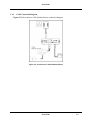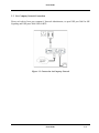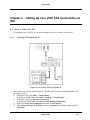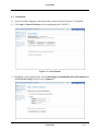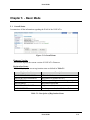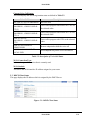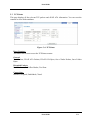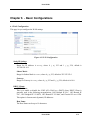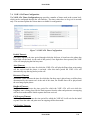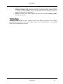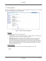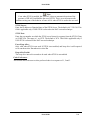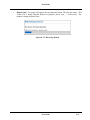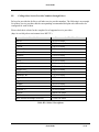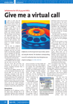
1
User Guide ® Netopia VOIP ATA User’s Guide User Guide 1-1 User Guide REVISION STATUS User Guide 1-2 User Guide Tables Of Content Chapter 1 - Introduction ............................................................................................... 1-6 1.1 Main features ............................................................................. 1-7 Chapter 2 - Your VOIP ATA at a glance ...................................................................... 2-8 2.1 Ports and buttons........................................................................ 2-8 2.2 LED description......................................................................... 2-9 Chapter 3 - Installing Your VOIP ATA ...................................................................... 3-10 3.1 Typical VOIP ATA Connection ............................................... 3-10 3.1.1 ADSL Connection Diagram ..................................................... 3-10 3.1.2 Cable Connection Diagram ...................................................... 3-11 3.2 For Company Network Connection.......................................... 3-12 Chapter 4 - Setting Up Your VOIP ATA functionality via GUI .................................. 4-13 4.1 Access to VOIP ATA’s GUI .................................................... 4-13 4.1.1 Accessing GUI Using Static IP ................................................ 4-13 4.1.2 Accessing GUI Using Hub/Switch ........................................... 4-15 4.2 Setup Mode.............................................................................. 4-17 Chapter 5 - Basic Mode.............................................................................................. 5-19 5.1 Overall Status .......................................................................... 5-19 5.2 DHCP Client Status ................................................................. 5-20 5.3 TCP Status............................................................................... 5-21 5.4 System Log.............................................................................. 5-22 Chapter 6 - Basic Configurations................................................................................ 6-23 6.1 WAN Configuration................................................................. 6-23 6.2 DNS Configuration .................................................................. 6-24 6.3 Save Settings / Reboot ............................................................. 6-26 Chapter 7 – Advanced Mode ...................................................................................... 7-28 7.1 VOIP ATA Configuration........................................................ 7-28 7.2 SIP Service Provider ................................................................ 7-30 7.3 VOIP ATA Login Account Configuration................................ 7-33 7.4 VOIP ATA Timer Configuration.............................................. 7-35 7.5 Ringtone Configuration............................................................ 7-38 7.6 Misc Configuration .................................................................. 7-42 User Guide 1-3 User Guide 7.7 Address Book Configuration.................................................... 7-45 Chapter 8 – Admin Privilege ...................................................................................... 8-48 8.1 Miscellaneous Configuration.................................................... 8-48 8.2 Admin / Username Password Configuration............................. 8-49 8.3 Reset to Default ....................................................................... 8-51 8.4 Firmware Update ..................................................................... 8-52 8.4.1 How to Firmware Update......................................................... 8-52 8.5 Save / Reboot........................................................................... 8-54 Chapter 9 Making Phone Calls ................................................................................... 9-56 9.1 Internet Calls ........................................................................... 9-56 9.2 PSTN Calls .............................................................................. 9-56 9.3 VoIP Advanced Call Features .................................................. 9-56 9.3.1 Consultation Hold .................................................................... 9-56 9.3.2 Blind Transfer.......................................................................... 9-56 9.3.3 Attended Transfer .................................................................... 9-57 9.3.4 3-Way Conferencing ................................................................ 9-57 9.3.5 Call Waiting............................................................................. 9-57 9.3.6 Call Forwarding ....................................................................... 9-58 9.3.6.1 Forward Unconditional.............................................. 9-59 9.3.6.2 Forward When Busy.................................................. 9-59 9.3.6.3 Forward On No Answer............................................. 9-59 9.3.6.4 Canceling Call Forwarding ........................................ 9-60 9.3.7 Call Return .............................................................................. 9-60 9.3.8 IP Dialing ................................................................................ 9-60 9.3.8.1 IP Address................................................................. 9-60 9.3.8.2 Through Server.......................................................... 9-60 Chapter 10 - Troubleshooting..................................................................................... 10-61 Appendix A Appendix B Glossary ............................................................................................. 10-62 A1 Acronyms .............................................................................. 10-62 A2 Keywords............................................................................... 10-62 A3 Definitions ............................................................................. 10-62 Dial Plan for Pulver ............................................................................ 10-66 B1 Basic Dial Plan ...................................................................... 10-66 B1.1 Pulver - USA Dial Plan .......................................................... 10-66 User Guide 1-4 User Guide B1.2 Explanation of the Rules ........................................................ 10-66 B2 Calling Other Service Provider Numbers through Pulver........ 10-68 User Guide 1-5 User Guide Chapter 1 - Introduction The VOIP ATA VoIP Analog Telephone Adaptor (VOIP ATA) products are standards-based communication devices that deliver true, next-generation voice-over-IP (VoIP) terminations to residences worldwide. The VOIP ATA is in a small form factor that interface legacy analog telephones, fax machines, analog conference telephones and other analog devices to IP based telephony networks thereby allowing users and ISPs to protect prior investments in analog phones, fax machines, and speakerphones, and migrate to IP at their own pace. These products address the needs of small-office environments, and the emerging VoIP voice services whereby ISPs value add their ADSL or Cable Modem offering with VoIP services by turning their analog devices into IP devices. The VOIP ATA is installed at the subscriber's premises and supports 1 voice (FXS) port. The VOIP ATA supports 1 10/100BaseT AutoMDIX Ethernet ports. This adaptor can make use of existing broadband pipes such as digital subscriber line (DSL), fixed wireless and cable modem deployments By turning any analog telephone into an IP telephone, the VOIP ATAs addresses the needs of the emerging market of "second-line" residential voice-over-IP (VoIP) services. Broadband service providers can now deploy voice services quickly to grow revenues and facilitate the development of new services. User Guide 1-6 User Guide 1.1 Main features • Call Out & Call In • Voice over IP c all (through Gatekeeper) • IP address calling / Peer to Peer calling (Future Firmware Upgrade) • 3Way IP Conference call • • • • • • Call features Call Waiting Call Hold Call Forward: No Answer / Busy / All Call ID (Type 1 and 2) Call Transfer (Dependant on ITSP) • Setup & Configuration • Web Based Configuration • Password Protection for Web Configuration • • • • • • • Audio Codec Feature G.711, G.726, G.729a Voice Activity Detection Silence Compression Comfort Noise Generation Echo Cancellation Jitter Provisioning • Protocols • SIP v2.0 • T.38 Fax over IP support • • • • • • • • Network Support Static IP Support NAT Traversal with STUN client NAT Traversal with outbound proxy DHCP Client DNS Relay Agent Single VPN Pass Through for IPSEC, L2TP, PPTP FTP and Web Management Support User Guide 1-7 User Guide Chapter 2 - Your VOIP ATA at a glance The VOIP ATA may have different ports and LEDs. Let’s take a look at the different options. Depending upon your model, it may have some or all of the features listed below 2.1 Ports and buttons Fig 2-1 shows the back panel of the VOIP ATA. Figure 2-1 : Back Panel 12V DC MODEM RESET PHONE DESCRIPTIONS This is where you will connect the included power adapter. The MODEM port allows you to connect the VOIP ATA to your router or gateway using a Category 5 (or better) Ethernet network cable (RJ-45). Press and hold the RESET button for 2 to 4 seconds will restore the VOIP ATA’s WAN Static IP to 192.168.1.200 while keeping all the other settings intact. Press and hold the RESET button for more than 5 seconds will restore the VOIP ATA to default factory settings. The PHONE port allows you to connect your telephone to the VOIP ATA using a RJ-11 telephone cable. Table 2-1 : Back Panel Descriptions Warning! All custamized setting that you have saved will be lost upon resetting the VOIP ATA to default factory settings will User Guide 2-8 User Guide 2.2 LED description Fig 2-2 shows the LED indicators of the VOIP ATA. Figure 2-2 : LED Indicators LED PWR ETH STATUS On On Blinking Off PHONE On Blinking Off DESCRIPTIONS The VOIP ATA is receiving power. The VOIP ATA has an Ethernet connection with cable/DSL modem. The VOIP ATA is sending/receiving dVoIP ATA to/from the cable/DSL modem. The VOIP ATA doesn’t have an Ethernet connection with the cable/DSL modem. This port(s) is registered to the Internet Phone Service Provider(s). The telephone(s) connected to this port(s) is(are) off-hooked. This port(s) isn’t registered to the Internet Phone Service Provider(s). Table 2-2 : LED Descriptions User Guide 2-9 User Guide Chapter 3 - Installing Your VOIP ATA 3.1 Typical VOIP ATA Connection You need to have a ADSL modem or Cable modem before you can connect to the VOIP ATA. It can be placed behind router or straight from the modem. Check if your Computer/Notebook has an Ethernet Port. The Telephone set is connected to the RJ-11 3.1.1 ADSL Connection Diagram Figure 3-1 below shows a ADSL Modem+Router connection diagram. Figure 3-1: Connection via ADSL Modem+Router User Guide 3-10 User Guide 3.1.2 Cable Connection Diagram Figure 3-2 below shows a Cable Modem+Router connection diagram. Figure 3-2: Connection via Cable Modem+Router User Guide 3-11 User Guide 3.2 For Company Network Connection Please seek advise from your company’s Network Administrator, to open UDP port 5060 for SIP Signaling and UDP ports 5000-5020 for RTP. Figure 3-3: Connection via Company Network User Guide 3-12 User Guide Chapter 4 - Setting Up Your VOIP ATA functionality via GUI 4.1 Access to VOIP ATA’s GUI To configure your VOIP ATA, you need to login to the device using a web browser. 4.1.1 Accessing GUI Using Static IP Figure 4.1: Accessing GUI Using Static IP These instructions are for the Windows 98, Windows ME, Windows 2000 and Windows XP operating systems. 1) In Windows XP, click Start-> Control Panel. In Windows 98/ME/2000, click Start-> Settings-> Control Panel. 2) In Windows XP, click Network Connections. In Windows 98/ME/2000, click Network and Dial-up Connections. 3) Right-click Local Area Connection and then click Properties. 4) Select Internet Protocol (TCP/IP) (under the General tab in Windows XP) and click Properties. User Guide 4-13 User Guide 5) Select Use the following IP address and enter information as below: IP address : 192.168.1.XXX (IP Address set must be unique) Subnet mask : 255.255.255.0 Default gateway : -Blank- User Guide 4-14 User Guide 6) Click OK to close the Internet Protocol (TCP/IP) Properties window. 7) Click Close (OK in Window 98/ME/2000) to close the Local Area Connection Properties window. 8) Close the Network Connections screen. 9) Launch your web browser and enter “192.168.1.200” at the address bar and hit Enter. 4.1.2 Accessing GUI Using Hub/Switch Figure 4.2: Accessing GUI Using Hub/Switch If your Router’s LAN is already in the192.168.1.XXX subnet, simply launch your web browser and enter “192.168.1.200” (VOIP ATA’s Static IP) at the address bar and hit Enter. If you Router’s LAN is using subnet other than 192.168.1.XXX: Steps: 1) Access the VOIP ATA’s GUI using Static IP (Refer to 3.2.1) and set the VOIP ATA as a DHCP client. 2) Access Router’s GUI. 3) Find out the IP Address, which have been assigned to VOIP ATA. Tip! Use VOIP ATA’s MAC Address as a reference. User Guide 4-15 User Guide 4) Launch your web browser and enter the assigned IP Address at the address bar and hit Enter. User Guide 4-16 User Guide 4.2 Setup Mode. 1) Upon successfully logging in, the Setup mode screen as shown in Figure 4.3 is displayed. 2) Click Step 1: Network Selection to start configurating the VOIP ATA. Figure 4.3 : Overall Status 3) Depending to your System Setup, select Connecting to a broadband router/cable modem and click Proceed to Step 2. Please refer to Figure 4.4. User Guide 4-17 User Guide Figure 4.4 : Network Selection 4) Fill in the fields with information exactly as it was given to you by your ITSP (Internet Telephony Service Provider) or network administrator. Please refer to Figure 4.5. Figure 4.5 : Step 2 5) Click Finish to save configuration and reboot the VOIP ATA. Please refer to Figure 4.6. 6) Click the Refresh button on your web browser after approximately 30-50 seconds. Figure 4.6: Saving Configuration User Guide 4-18 User Guide Chapter 5 - Basic Mode 5.1 Overall Status It summarizes all the information regarding the WAN of the VOIP ATA. Figure: 5-2: Overall Status Firmware Version: This section displays the current version of VOIP ATA Firmware. Registration Status: This field displays the current registration status as defined in Table 5.1. Registration Status VOIP SERVICE DISABLED REGISTRATION DISABLED REGISTERING… REGISTERED REGISTRATION FAILED UNREGISTERED Descriptions SIP is disabled Registration is disabled on GUI WAN is up and Registration is being attempted Registration succeeded Registration failed Board is powered on, but WAN is still down Table 5-1: Description of Registration Status User Guide 5-19 User Guide Current Voice Call Status: This field displays the current registration status as defined in Table 5.2. Voice Call Status NO VOICE CALL IN PROGRESS VOICE CALL IN PROGRESS…CODEC USED IS G711U VOICE CALL IN PROGRESS…CODEC USED IS G711A VOICE CALL IN PROGRESS…CODEC USED IS G729 VOICE CALL HELD BY REMOTE END VOICE CALL ON HOLD BY LOCAL END Descriptions No voice calls Voice call in progress with PCMU or G711U as the selected codec Voice call in progress with PCMA or G711A as the selected codec Voice call in progress with G729 as the selected codec Remote endpoint has held the voice call Local endpoint has put the voice call on hold Table 5-2: Description of Voice Call Status WAN Connection Type: It shows the type of connection that is currently used. WAN Statistic: This shows the WAN interface IP address assigned to your router. 5.2 DHCP Client Status This page displays the IP address which is assigned by the DHCP Server. Figure: 5-3: DHCP Client Status User Guide 5-20 User Guide 5.3 TCP Status This page displays all the relevant TCP packets and dVoIP ATA information. You can reset the counters to clear all the attributes. Figure: 5-4: TCP Status Reset Counters: This button allows user to reset the TCP Status counter. General: Total Packets, DVoIP ATA Packets, DVoIP ATA Bytes, Out of Order Packets, Out of Order Bytes Discarded Packets: Bad Checksum, Bad Offset Header, Too Short Connections: Initiated, Accepted, Established, Closed. User Guide 5-21 User Guide 5.4 System Log The System Log page shows the events triggered by the system. This page contains dynamic information and will refresh every 10 seconds. Figure: 5-5: System Log Clear Log: This field allows you to clear the current contents of the System Log. Save Log: This field allows you to save the current contents of the System Log by right clicking ‘here’ and select “Save Target As” to save it into a text file. User Guide 5-22 User Guide Chapter 6 - Basic Configurations 6.1 WAN Configuration This page let you configure the WAN settings. Figure 6-1 WAN Configuration Static IP Settings: IP Address: Range for IP Address is x.x.x.y, where 0 ≤ x≤ 255 and 1 ≤ y≤ 254, default is 192.168.241.101. Subnet Mask: Range for Subnet Mask is x.x.x.x, where 0 ≤ x≤ 255, default is 255.255.255.0 Gateway: Range for Gateway is x.x.x.y, where 0 ≤ x≤ 255 and 1 ≤ y≤ 254, default is 0.0.0.0. DHCP Clients: DHCP Client: This is to enable or disable the VOIP ATA WAN as a DHCP client. DHCP Client is generally used in the following encapsulations: 1483 Bridged IP LLC, 1483 Routed IP LLC, 1483 Bridged IP VC-MUX, 1483 Routed IP VC-Mux, and Classical IP over ATM. This option is for non-static (dynamic) IP addresses. Host Name: The Host Name can be up to 19 characters. User Guide 6-23 User Guide 6.2 DNS Configuration The DNS Configuration page allows you to set the configuration of the DNS proxy. Figure 6-2 DNS Configuration DNS Proxy: When the DNS Proxy is Disabled, the LAN port does not process the DNS query message. For the DHCP requests from local PCs, the DHCP server will set the user-configured DNS server as the DNS server. Then all DNS query messages will be directly sent to the DNS servers. DNS Proxy is enabled by default. Auto Discovered: When enabled (default), the DNS proxy will store the DNS server IP addresses obtained from DHCP client or PPP into the table. All DNS query messages will be sent to the dynamically obtained DNS server. Select this option when the DNS Server address is unknown but provided (automatically) by the ISP. User Configured: When enabled, the DNS proxy will use the user-configured DNS server. All DNS query messages will be sent to the DNS server. Enter the DNS IP in the DNS Server field. Select this option when the DNS Server address assigned by the ISP is known. User Configured is disabled by default. DNS Server: This is the user defined DNS server URL name and IP. Default is disabled. URL Name: User Guide 6-24 User Guide This is the URL name for the DNS server. This can be up to 255 characters. Host IP: This is the IP address of the DNS Server. DNS Proxy Setting: This is a table of all DNS server IP addresses. DNS Server Setting: This is a table of all DNS sever URL names. Save Configuration: Clicking this will link the user to the Save Settings / Reboot page. User Guide 6-25 User Guide 6.3 Save Settings / Reboot You can save the custimized settings in this section Figure 6-3 Save Settings / Reboot Save & Reboot: Click this to apply all changes. Reboot Only: Do this to discard all changes since last save. After either one of these buttons are clicked, the ADSL Bridge/Router will do the following: • Save & Reboot: Two pages will appear after pressing this button. The first one states: “Your settings are being saved and the modem being rebooted. Save reboot in progress, please wait….” Followed by “Your settings have been saved and the modem has rebooted. Done” Figure 6-4 Save Settings • Reboot Only: Two pages will appear after pressing this button. The first one states: “The VOIP ATA is being rebooted. Reboot in progress, please wait….” Followed by “The modem is being rebooted. Done.” User Guide 6-26 User Guide Figure 6-5 Rebooting Modem User Guide 6-27 User Guide Chapter 7 – Advanced Mode It provides a brief outline of the advanced features of individual hyper links on the left menu. 7.1 VOIP ATA Configuration The VOIP ATA Configuration page allows you to set different parameters of the VoIP application. Figure 7-1 VOIP ATA Configuration PTM Software Version details: This section displays the current version of the PTM module. Service Provider To Use: This parameter holds the service provider selected to work with the VOIP ATA for the above chosen Line. Different service provider specific details can be configured by clicking the link Update Service Provider. When a different service provider is chosen from the Drop-down list, the Login Account To Use drop-down list is updated to reflect the login details available and configured for the selected service provider. Login Account To Use: This parameter holds the Login Account selected to work with the VOIP ATA for the above chosen Line and the Service Provider. Different Login Account details can be configured by clicking the link Update User Login Account. This permits multiple logins to be created per service provider. Further, SIP protocol also allows the same login to be used for registration from multiple locations. So the same login under the same service provider can be used from multiple lines. Current Registration Status: This field displays the current registration status of this line. If the line is registered it shows the status as REGISTERED else it shows UNREGISTERED. User Guide 7-28 User Guide Note There will not be any Dial Tone when WAN interface is down or Registration is Failed. User Guide 7-29 User Guide 7.2 SIP Service Provider The VOIP ATA SIP Service Provider Configuration page allows the user to set the configuration related to the SIP service provider. Figure 7-2 VOIP ATA SIP Service Provider Configuration Service Provider List: • This selection is a drop-down box, which allows the user to select the Service Provider for which the configuration needs to be done. When a service provider is selected from this dynamic list, the respective parameters are automatically displayed. • A DEFAULT set of parameters is provided for every new service provider added. This can be edited accordingly. New service providers can be defined and added manually by the user. An existing service provider can be edited or even deleted. New Service Provider: New Service Provider is a text-field where the user can enter the name of the new service provider to be added, or a new string to rename an existing service provider. The service provider edited will be the one chosen from the Working Service Provider field. Registration Interval: This parameter specifies the re-registration interval in seconds. Registrar Address: This parameter gives the IP address of the registrar with which the VOIP ATA must register in order to receive incoming calls. Proxy Address: This parameter is the IP address of the SIP proxy server. OutboundProxy Address: User Guide 7-30 User Guide This parameter is the IP address of the Outbound proxy server. This is useful in cases where the VOIP ATA is behind a NAT. User Guide 7-31 User Guide Authentication Method: This parameter indicates the authentication method. Currently, only MD5 is supported. • AUTH_NONE: Disable any authentication method • AUTH_MD5: Use MD5 authentication method. Registrar Port: This parameter informs the port of the registrar on which it will listen for Register requests from the VOIP ATA. (Default Port is 5060) Note Range for Registrar port address is between 5000 and 65535. Proxy Port: This parameter is the port on which the SIP proxy server will listen for messages. OutboundProxy Port: This parameter is the port on which the outbound proxy server listens for messages from the VOIP ATA. Service Provider Action: The VOIP ATA provides a drop-down option (Display, Add, or Edit or Delete) for the user to manipulate the various SIP and dial plan parameters for working service provider. Parameters for a service provider can be displayed, added, and edited. • Display: This is the default option; selection of this option will display the selected service provider in the Working Service Provider field after clicking on the Submit button. • Add: Selection of the Add option adds a new service provider after clicking on the Submit button according to the value that appears in the Working Service Provider field (which must not be empty). • Edit: Selection of edit option will overwrite the selected service provider’s (according the Working Service provider field) parameters with the current parameters displayed on the web page. The New Service Provider field is optional and it needs to be filled only when the service provider name also has to be changed. • Delete: Selection of Delete option will delete the selected Working Service Provider from the Service Provider list. User Guide 7-32 User Guide 7.3 VOIP ATA Login Account Configuration The VOIP ATA Login Account Configuration page allows the user to set and configure login accounts for the service provider chosen in the index webpage, i.e., for the currently selected service provider in the main webpage. Figure 7-3 VOIP ATA Login Account Configuration User Profile List: This selection is a drop-down box, which allows the user to select the login account for which the configuration needs to be done. When a login account is selected from this dynamic list, the respective parameters are automatically displayed. A DEFAULT set of parameters is provided for every new login added. This can be edited accordingly. New logins can be defined and added manually by the user. An existing login account can also be edited or even deleted. New User Profile: New User Name is a text-field where the user can enter the name of the new login account to be added, or a new string to rename an existing login account. The login account edited will be the one chosen from the Service Provider List field. Auth User ID: This parameters is for authentication with the registrar. If not specified explicitly by ITSP, this is the same as the User Name. User Name: This parameter holds the registration ID of the user with the registrar. Password: This parameter holds the Password used for authentication with the registrar. Display Name: This parameter holds the Display Name, as it should appear on the Caller-Id. User Guide 7-33 User Guide Login Action: The VOIP ATA provides a drop-down option (Display, Add, or Edit or Delete) for the user to manipulate the various login parameters for login account chosen in the Login Account List. Parameters for a login account can be displayed, added, and edited. • • • • Display: This is the default option; selection of this option will display the selected login details after clicking on the Submit button. Add: Selection of the Add option adds a new login account after clicking on the Submit button according to the value that appears in the New Account Name field (which must not be empty). Edit: Selection of edit option will overwrite the selected login’s (in the Login List field) parameters with the current parameters displayed on the web page. The New Login field is optional and it needs to be filled only when the login account name also has to be changed. Delete: Selection of Delete option will delete the selected Login Account from the Login Account List. Submit Changes: Clicking on this button will save settings to the board RAM. In order to save changes permanently to the firmware and to make them effective, the setting should be saved by going to the Save Settings/Reboot web. Note 1) The above parameters are Service Provider specific and are reflected for the Service Provider that was shown as selected in the VOIP ATA index webpage before arriving through the link Update User Login Account Configuration. 2) The maximum number of login accounts you can add is 4 per service provider and there must be at least 1 login account per service provider available. User Guide 7-34 User Guide 7.4 VOIP ATA Timer Configuration The VOIP ATA Timer Configuration page provides a number of timers used at the system level, which can be configured through the web interface. The timer values have to be given in seconds only. This section explains the various timers available for configuration. Figure 7-4 VOIP ATA Timer Configuration Predial Timeout: Dial timer indicates the time period through which the dial tone is heard once the phone has been lifted off the hook. At the end of this period, if no digits have been pressed, the VOIP ATA will start playing the fast-busy tone. Alert Timeout: Alert Timer indicates the time for which the VOIP ATA will play the Ring when an incoming call has arrived and the phone is on-hook. After this timer period the VOIP ATA will automatically stop the ring and reject the call. Disconnect Timeout: Disconnect Timer indicates the time for which the fast-busy tone is played once a call has been disconnected by the remote-end. At the end of this time, the Warble tone will be played until the user hangs up the phone. RingBack Timeout: RingBack Timer indicates the time period for which the VOIP ATA will wait while the RingBack tone is being played for the final response from the other end point once an outgoing call has been made and the initial response has been received. Call Progress Timeout: CallProgress Timer indicates the time period for which the VOIP ATA will wait for the initial response from the other end point once an outgoing call has been made. Call Waiting Timeout: User Guide 7-35 User Guide CallWaiting Timer indicates the period for which the call-waiting tone will be played when an incoming call arrives in the connected state. The Call Waiting tone is played at an interval of 10 sec. It is configurable using the Call Waiting tone parameters. User Guide 7-36 User Guide Call Fwd No Ans Timeout: CallFwdNoAns Timer indicates the time after which the call will be forwarded when not answered by anyone. This timer is applicable when Call Forwarding on No Answer is enabled. Submit Changes: Clicking on this button will save settings to the board RAM. In order to save changes permanently to the firmware and to make them effective, the setting must be saved by going to the Save Settings/Reboot web page User Guide 7-37 User Guide 7.5 Ringtone Configuration The Country Specific Ring & Tones Configuration page is used to define the parameters for the various tones (ring, dial, busy, ring back etc.) that are generated by the VOIP ATA application. VOIP ATA provides default Ring-Tone Parameters configured for various Countries. Flexibility is provided to change the existing ring-tone parameters and add new countries and also edit/delete existing countries. Figure 7-5 Country Specific Ring & Tones Working Country: This selection is a drop-down box, which allows the user to select the country for which the VOIP ATA configuration must work. Currently, it is applicable for the ring-tone parameters only. When a country is selected from this dynamic list, the country parameters are automatically displayed. Supported Countries: USA, Singapore, Hong Kong, Australia New countries can be defined and added manually by the user. New Country: New Country is a text-field where the user can enter the country name to be added or a new string to edit an existing country. The country edited will be the one chosen from the Working Country field Ring Parameters: User Guide 7-38 User Guide The Ring Parameters are defined by five fields: Frequency, OnTime1, OffTime1, OnTime2, and OffTime2. Time values are in milliseconds. Frequency is given in hertz. User Guide 7-39 User Guide Normal Dial Tone: The dial tone parameters are defined by six fields: Freq1, Freq2, OnTime1, OffTime1, OnTime2, and OffTime2. RingBack tone: The ring back tone parameters are defined by six fields: Freq1, Freq2, OnTime1, OffTime1, OnTime2, and OffTime2. Alerting Tone: The alerting tone parameters are defined by six fields: Freq1, Freq2, OnTime1, OffTime1, OnTime2, and OffTime2. Recall Tone: The recall tone parameters are defined by five fields: Freq1, Freq2, OnTime1, OffTime1 and Duration. Busy Tone: The busy tone parameters are defined by six fields: Freq1, Freq2, OnTime1, OffTime1, OnTime2, and OffTime2. Call waiting Tone: The call waiting tone parameters are defined by six fields: Freq1, Freq2, OnTime1, OffTime1, OnTime2, and OffTime2. Congestion Tone: The congestion tone parameters are defined by six fields: Freq1, Freq2, OnTime1, OffTime1, OnTime2, and OffTime2. Stutter Dial Tone: The stutter dial tone parameters are defined by five fields: Freq1, Freq2, OnTime1, OffTime1 and Duration. VMI Dial Tone: The stutter dial tone parameters are defined by five fields: Freq1, Freq2, OnTime1, OffTime1 and stutter Duration. This plays a distinctive stutter dial tone on Off Hook when there are Voice Mails waiting on the phone. Ring Tone Action: The VOIP ATA provides a drop-down option (Display, Add, or Edit or Delete) for the user to manipulate the ring-tone parameters for the working country. Ring-tone parameters for a country can be displayed, added, and edited. • Display: This is the default option. Selection of this option will display the selected country in the Working Country field after clicking on the Submit button. • Add: Selection of the Add option adds a new country after clicking on the Submit button according to the value that appears in the Working Country field. This field must not be empty. User Guide 7-40 User Guide • • Edit: Selection of edit option will overwrite the selected country’s (according the Working Country field) parameters with the current parameters displayed on the web page. The New Country field is optional and needs to be filled only when the country name also has to be changed. Delete: Selection of the Delete option will delete the selected Working Country from the country list. Submit Changes: Clicking on this button will save settings to the board RAM. In order to save changes permanently to the firmware and to make them effective, the setting should be saved by going to the Save Settings/Reboot web page User Guide 7-41 User Guide 7.6 Misc Configuration The Misc Configuration pages configures system-level parameters. This has three sections: SIP Device, STUN Parameters and Codec Preference. Figure 7-6 VOIP ATA Misc Configuration SIP Device: This section configures the following infomartion: • Local SIP Port: Enter the local SIP Port number on which VOIP ATA should listen for the messages. The range is 1 to 65535. (Default port is 5060) • Media Base Port: Enter the Media Base Port (also known as RTP port) number. This parameter provides the base value from the media (RTP) ports that are assigned for various lines and the different call-sessions that may exist within an end-point. Odd port values are not recommended. If an Odd Value is entered, the next higher even value is used as the Media Base Port. This is to conform to the RFC specifications. The range is 1 to 65500. (Default port is 5000) STUN Parameters: This section configures for the NAT Traversal technique support in VOIP ATA. STUN: User Guide 7-42 User Guide Select ENABLED to enable STUN (default) if the VOIP ATA is behind a NAT enabled router and the router has no ALG for SIP, or DISABLED to disable STUN (VOIP ATA is not to use STUN for NAT traversal). VOIP ATA also supports a proprietary implementation of NAT traversal where the Service provider is expected to provide some relay support. If DISABLED is selected, then based on the responses received, the VOIP ATA will dynamically determine if the SIP Server supports the proprietary implementation. User Guide 7-43 User Guide Note Even when STUN is enabled, the VOIP ATA does an automatic detection of the presence of SIP ALG and disables the use of STUN. This is to avoid some media problems arising out of the behavior of some ALGs when STUN is used at the user end. STUN Server: Enter the IP address or Domain Name of the STUN Server. The default is 66.7.238.210. This field is applicable only if USE STUN is selected as the NAT traversal technique. STUN Port: Enter the port number on which the STUN server listens for requests from the STUN Client on VOIP ATA. The range is 1 to 65535. The default is 3478. This field is applicable only if USE STUN is selected as the NAT traversal technique. Force Keep Alive: Only valid when STUN is not used. If STUN is not enabled, and keep alive is still expected to be sent then select Yes otherwise select No. Keep Alive Period: The keep alive interval in seconds to be used when STUN is not enabled. Codec Preference: This section allows the user to select preferred codec in a sequence of 1, 2 and 3. User Guide 7-44 User Guide 7.7 Address Book Configuration The Address Book Configuration web page allows for configuration of address book entries which can be used for speed dial execution of calls. Figure 7-5 Address Book The top half of the web page displays the current address book table. The bottom half of the web page can be used for editing the address book. This includes adding new entries, deleting existing entries, modifying existing entries and displaying the values corresponding to an entry index or speed dial index in the address book. Address Book Table: This table displays the current address book as configured for this endpoint. Display Name: Enter the Display Name for this address book entry. Number: The user phone number or name for this entry. This field is optional, if the IP Address is specified. A phone number that can be reached through the current configured proxy server can also be added as an entry in which case the IP address/Domain name and the Port number fields are not necessary. IP Address/Domain Name: Enter the IP address or the domain name that corresponds to this address book entry. If this field is left empty, then the User number or name must be specified, in which case the current configured proxy server for this endpoint will be used as the domain name. User Guide 7-45 User Guide Port Number: Specify the SIP port number on which the remote end will receive our call. This is useful when you want to specify a non-phone number entry, where the call can be made directly without going through the configured proxy server. When this field is not specified, the default SIP port of 5060 will be assumed. User Guide 7-46 User Guide Speed dial code: This refers to the index in the address book as well as the speed dial entry code. This needs to be specified following *78 to dial out the number corresponding to this address book entry. Address Book Action: Select a drop-down option (DISPLAY, ADD, EDIT, or DELETE) to manipulate the various address book parameters for the entry index selected from the speed dial code drop down box. • DISPLAY: Select DISPLAY for the selected speed dial code details to be displayed after clicking Submit Changes. This is the default selection. • ADD: Select ADD to add a new address book entry after clicking Submit Changes. • EDIT: Select EDIT to overwrite the selected address book entry. • DELETE: Select DELETE to delete the selected address book entry Submit Changes: Click Submit Changes to save the settings on this page to system RAM and Flash also. Note 1) Up to ten addresses book entries can be added. 2) Address book entries addition/deletion/editing do not need a Save and Reboot. The changes will take effect immediately User Guide 7-47 User Guide Chapter 8 – Admin Privilege 8.1 Miscellaneous Configuration This page allows you to configure the miscellaneous configurations such as HTTP, FTP, TFTP and SNTP. Figure 8-1 Miscellaneous Configurations HTTP Server: HTTP Server Access: This field allows you to configure where these Web pages can be accessed from. • All: When this field is checked, it allows both WAN access to the Web pages. (Default is Enabled) • Restricted WAN Specified IP & Subnet Mask: This field allows the Web access from WAN side with a specify IP and subnet mask. HTTP Server Port: This field allows you to specify the port of the Web access. (Default is Port 80) Note.. Range for HTTP Server port is 0 – 32767. User Guide 8-48 User Guide HTTP Password Protection: This field allows you to enable or disable the HTTP authentication. (Default is Disabled) FTP Server: This field allows you to enable or disable the FTP server connection. (Default is Enabled) • Disable WAN side FTP access: This will disable WAN side access to the FTP server. (Default is Disabled) TFTP Server: This field allows you to enable or disable the TFTP connection. System default is Disabled. SNTP Client: SNTP: Simple Network Time Protocol is an efficient method of obtaining the time from a Time Server. Time Zone: This specifies the time zone (geographical location). Daylight Saving Time: Select to enable or disable Daylight Saving Option. User Defined Time Server: Specified the IP address of your preferred SNTP server TIP! When the VOIP ATA is successfully connected to the SNTP server, the system log will reflect the updated time 8.2 Admin / Username Password Configuration This page allows you to change password for the administrator. Figure 8-2 Admin Username / Password Configuration Enter the password in both of the text fields. Make sure that the password is at least 8 characters long and do not contain '&'. (Default Password is epicrouter) User Guide 8-49 User Guide Note.. FTP uses the same Username and Password. Ensure to click Submit and Save Settings for your configuration to take effect. User Guide 8-50 User Guide 8.3 Reset to Default This page allows you to reset the VOIP ATA to original factory default configuration. Figure 8-3: Restore Settings Click on Restore button to restore to factory default settings. Note.. This feature produces the same effect as press the Reset Button for more than 5 seconds.. User Guide 8-51 User Guide 8.4 Firmware Update This page allows the user to upgrade the firmware via web interface. Figure 8-4: Firmware Update 8.4.1 How to Firmware Update 1) Access Firmware Update GUI at Advanced Firmware Update. 2) On the Firmware Update GUI as in Figure 8-4, click Firmware Update and GUI as in Figure 8-5 will be displayed, showing that VOIP ATA is preparing itself to attempt Firmware Update. Figure 8-5: Preparing to Download User Guide 8-52 User Guide Figure 8-6: Uploading .DLF file 3) Refering to Figure 8-6 , click Browse, search for the correct .DLF file and click Upload to begin Firmware Update. 4) Click Cancel Update if you want to abort Firmware Update. Warning! As the uploading process will take about 1minutes, please do not turn off the VOIP ATA. 5) Firmware Updating is successful if GUI as shown in Figure 8-7 is displayed. Figure 8-7: Firmware Update Successful 6) As by default the VOIP ATA is set to Static IP, please refer to 4.1.1 on How to Access the GUI. User Guide 8-53 User Guide 8.5 Save / Reboot This page allows you to save the new configurations to the flash and reboot the VOIP ATA or simply reboot the VOIP ATA without saving changes. Figure 8-13: Save / Reboot Save & Reboot: Click this to apply all changes. Reboot Only: Do this to discard all changes since last save. After either one of these buttons are clicked, the ADSL Bridge/Router will do the following: • Save & Reboot: Two pages will appear after pressing this button. The first one states: “Your settings are being saved and the modem being rebooted. Save reboot in progress, please wait….” Followed by “Your settings have been saved and the modem has rebooted. Done” Figure 8-14: Save Settings User Guide 8-54 User Guide • Reboot Only: Two pages will appear after pressing this button. The first one states: “The VOIP ATA is being rebooted. Reboot in progress, please wait….” Followed by “The modem is being rebooted. Done.” Figure 8-15: Rebooting Modem User Guide 8-55 User Guide Chapter 9 Making Phone Calls 9.1 Internet Calls 1) To make a VoIP call, simply dial the SIP number on your phone’s dial pad. 9.2 PSTN Calls 1) To call regular PSTN telephone numbers, please use your ITSP’s dialing plan. 9.3 VoIP Advanced Call Features 9.3.1 Consultation Hold This feature allows a user to put the existing call on hold and call another number. How To: 1) Dial *83 followed by # on A’s dial-pad to disable 3-Way Conferencing for the duration of the following call. 2) Dial a number and during the existing call, press the flash button on the telephone handset to put the current remote party on hold and get a dial tone. 3) You can now dial another number. 4) When you are finished press flash to come back to the first call. You can also alternate between calls. 9.3.2 Blind Transfer This feature allows a user (transferor) to transfer an existing call (transferee) to another telephone number (transfer target) without calling it. How To: 1) During an existing call, press the flash button on the telephone handset to put the other party on hold and get a dial tone. 2) Press *90 (the blind transfer activation code) on your telephone dial pad, listen for the alert tone to indicate that the VOIP ATA is expecting a number, then enter the phone number to which you want to transfer the other party, then press # (optional). 3) Hang up your phone, once you hear the Fast Busy Tone. User Guide 9-56 User Guide 9.3.3 Attended Transfer This feature allows a user (transferor) to transfer an existing call (transferee) to another telephone number after first consulting with the dialed party (transfer target) before the user hangs up. How To: 1) During an existing call, press the flash button on the telephone handset to put the existing party on hold and get a dial tone. 2) Dial the telephone number to which the existing party is being transferred. 3) When the Transfer Target answers the phone, you may consult with the Transfer Target and then transfer the existing party (transferee) by hanging up your telephone handset. 9.3.4 3-Way Conferencing How To: 1) Dial the first number. 2) During existing call with the first party, press the flash button on the telephone handset. This will put the first party on hold and you will get a dial tone. 3) Dial a another number and talk to the second party. 4) To conference with both callers at the same time, perform a hook flash. 5) To drop the second call, perform a hook flash. Note: If you hang up during conferencing, both of them will be disconnected from the call. 9.3.5 Call Waiting If someone calls you while you are speaking on the telephone, the VOIP ATA indicates this by playing a CallWaiting Tone. You can answer this call by performing a hook flash. Tip! 1) When the VOIP ATA is configured to use Call Waiting, press *70 on your telephone dial-pad to disable Call Waiting for the duration of the following call. 2) You will hear a confirm tone followed by the dial tone. If you hang up with or without making the call, then the VOIP ATA enables Call-Waiting Tone again. User Guide 9-57 User Guide 9.3.6 Call Forwarding The VOIP ATA can control call forwarding at the end-point level. There are three types of call forwarding: • Forward Unconditional—Forwards every call that comes in. • Forward When Busy—Forwards calls when the line is busy. • Forward on No Answer—Forwards calls when the telephone is not answered after the configured period. User Guide 9-58 User Guide 9.3.6.1 Forward Unconditional How To: 1) Press *72 on your telephone dial-pad. 2) You will hear an alert tone very briefly, following which you can enter the number you want to forward call to; then press # again. 3) If you enter a number, then the VOIP ATA will attempt to call the number to which you intend to forward. Once you disconnect the attempted call, in subsequent call attempts you will listen stutter dial tone indicating that Forward Unconditional is enabled. 9.3.6.2 Forward When Busy How To: 1) Press *74 on your telephone dial-pad. 2) You will hear an alert tone very briefly, following which you can enter the number you want to forward call to; then press # again. 3) If you enter a number, then the VOIP ATA will attempt to call the number to which you intend to forward. Once you disconnect the attempted call, in subsequent call attempts you will listen normal dial tone only, but Call Forward when Busy will be enabled. 9.3.6.3 Forward On No Answer How To: 1) Press *75 on your telephone dial-pad. 2) You will hear an alert tone very briefly, following which you can enter the number you want to forward call to; then press # again. 3) If you enter a number, then the VOIP ATA will attempt to call the number to which you intend to forward. Once you disconnect the attempted call, in subsequent call attempts you will listen normal dial tone only, but Call Forward on No Answer will be enabled. 4) You can set the CallFwdNoAnswer time from the webpage, which indicates the time after which Call forwarding will take place. This timer is applicable for this feature only. User Guide 9-59 User Guide 9.3.6.4 Canceling Call Forwarding How To: To cancel unconditional call forwarding, press *73 on your telephone dial-pad. To cancel call forwarding on busy press *76 on your telephone dial-pad. To cancel call forwarding on no answer press *77 on your telephone dial-pad. 9.3.7 Call Return The VOIP ATA provides the facility to call back the last incoming call that may have been missed. This is especially useful when the phone doesn’t have caller-id facility or doesn’t support call-waiting caller-id. How To: Press *69 followed by # on your telephone dial-pad to return the last incoming call. 9.3.8 IP Dialing 9.3.8.1 IP Address 1) Press *47 on A’s dial-plan followed by the URL of B followed by a # sign to send out the call immediately 2) The B’s URL has the following syntax: <IP Segment 1>*<IP Segment 2>*<IP Segment 3>*<IP Segment 4> 9.3.8.2 Through Server 1) Press *47 on A’s dial-plan followed by the URL of B followed by a # sign to send out the call immediately 2) The B’s URL has the following syntax: <User Name>**<IP Segment 1>*<IP Segment 2>*<IP Segment 3>*<IP Segment 4>*<SIP Port> User Guide 9-60 User Guide Chapter 10 - Troubleshooting PROBLEM None of the LEDs turn on CORRECTIVE ACTION Make sure that you have the correct power adaptor connected to the VOIP ATA and plug into an appropriate power source. Check all cable connections. Cannot access the Internet Verify the Internet connection settings in the Overall Status screen. There is no dial tone Check the telephone connections. You can test the telephone wire by using it to connect a telephone to a regular telephone outlet and check for a dial tone. The dial tone beeps (pulses) Make sure you Voice Service Provider settings properly configured. The dial tone will be steady when the SIP account is registered. Cannot make or receive calls Check the SIP account status in the Overall Status screen. Make sure you Voice Service Provider settings properly configured. If you configured a SIP account to receive calls on only one of the phone ports, make sure your phone is connect to that port. User Guide 10-61 User Guide Appendix A Glossary The Glossary defines acronyms, keywords and definitions used in this user guide. A1 Acronyms VOIP ATA FXO FXS PSTN PTM RTP SIP STUN UA VoIP A2 Analog Telephony Adaptor Foreign Exchange Office Foreign Exchange Subscriber Public Switched Telephone Network Packet Telephony Module Real-time Transport Protocol Session Initiation Protocol Simple Transversal of UDP through NAT User Agent Voice over Internet Protocol Keywords Caller Callee Transferor Transferee Transfer Target A3 Call Originating End is called the Caller. The Call Terminating End is called the Callee. The End transferring the call. The End being transferred. The End to whom the transferee is being transferred. Definitions CPE Customer Premises Equipment: This specifies equipment on the customer, or LAN, side. CRC Cyclic Redundancy Checking: A method for checking errors in a dVoIP ATA transmission between two computers. CRC applies a polynomial function (16 or 32-bit) to a block of dVoIP ATA. The result of that polynomial is appended to the dVoIP ATA transmission. Upon receipt, the destination computer applies the same polynomial to the block of dVoIP ATA. If the host and destination computer share the same result, the transmission was successful. Otherwise, the sender is notified to re-send the dVoIP ATA block. User Guide 10-62 User Guide DHCP Dynamic Host Configuration Protocol: A communications protocol that allows network administrators to manage and assign IP addresses to computers within the network. DHCP provides a unique address to a computer in the network which enables it to connect to the Internet through Internet Protocol (IP). DHCP can lease and IP address or provide a permanent static address to those computers who need it (servers, etc.). User Guide 10-63 User Guide DNS Domain Name System: A method to locate and translate Domain Names into Internet Protocol (IP) addresses, where a Domain Name is a simple and meaningful name for an Internet address. FTP File Transfer Protocol: A standardized internet protocol which is the simplest way to transfer files from one computer to another over the internet. FTP uses the Internet's TCP/IP protocols to function. Gateway A point on the network, which is an entrance to another network. For example, a router is a gateway that connects a LAN to a WAN. Host In context of Internet Protocol, a host computer is one that has full two way access to other computers on the Internet. IP Internet Protocol: The method by which information is sent from one computer to another through the Internet. Each of these host computers have a unique IP address which distinguishes it from all the other computers on the internet. Each packet of dVoIP ATA sent includes the sender's IP address and the receiver’s IP address. LAN Local Area Network: A group of computers, typically covering a small geographic area, that share devices such as printers, hard disk drives, scanners, and optical drives. Computers in a LAN typically share an internet connection through some sort of router that connects the computers to a WAN. MAC Address Media Access Control Address: A unique hardware number on a computer or device that identifies it and relates it to the IP address of that device. Ping Packet Internet Groper: A utility used to determine whether a particular device is online or connected to a network by sending test packets and waiting for a response. Proxy A device that closes a straight connection from an outside network (WAN) to an inside network (LAN). All transmissions must go through the proxy to get into or out of the LAN. This makes the internal addresses of the devices in the LAN private. Subnet Mask Short for SUBNETwork Mask, subnet mask is a technique used by the IP protocol to filter messages into a particular network segment, called a subnet. The subnet mask consists of a binary pattern that is stored in the client computer, server, or router. This pattern is compared with the incoming IP address to determine whether to accept or reject the packet. TCP Transfer Control Protocol: Works together with Internet Protocol for sending dVoIP ATA between computers over the Internet. TCP keeps track of the packets, making sure that they are routed efficiently. TFTP Trivial File Transfer Protocol: A simple version of FTP protocol that has no password authentication or directory structure capability. User Guide 10-64 User Guide UDP User DVoIP ATAgram Protocol: A protocol that is used instead of TCP when reliable delivery is not required. Unlike TCP, UDP does not require an acknowledgement (handshake) from the receiving end. UDP sends packets in one-way transmissions. User Guide 10-65 User Guide Appendix B Dial Plan for Pulver B1 Basic Dial Plan An example dial plan string as would be used with Pulver (a globally available Void service provider - http://www.fwd.pulver.com) is given below. The dial plan string represents only the basic dialing call and service rules. B1.1 Pulver - USA Dial Plan [1-9]x.2t8>#x.6t4|*18x.8t8xt2>#|**484x.7t4>#|1:*72;>#x.etfxt2|2:*73;>#t4|3:*74;>#x.etfxt2| 4:*75;>#x.etfxt2|11:*70;>#t4|12:*69;>#t4||16:*90;x>#x.dtfxt2|18:*47;t4xt2>#|20:#;x.3>#x.atfxt2|22 :*83;x>#x.dtfxt2|23:*76;>#t4|24:*77;>#t4|[0-9*]>#[0-9*].e[0-9*].ft4 B1.2 Explanation of the Rules Rules [1-9]x.2t8>#x.6t4 *18x.8t8xt2># **484x.7t4># 1:*72;>#x.etfxt2 2:*73;>#t4 3:*74;>#x.etfxt2 4:*75;>#x.etfxt2 11:*70;>#t4 12:*69;>#t4 16:*90;x>#x.dtfxt2 18:*47;t4xt2># 20:#;x.3>#x.atfxt2 22:*83;x>#x.dtfxt2 23:*76;>#t4 24:*77;>#t4 [0-9*]>#[0-9*].e[0-9*].ft4 Descriptions Call any Pulver Number up to 9 digits, but minimum 3 digits Call any Toll Free Number through Pulver Account Call any Global Village Number. This rule demands a minimum and a maximum or 7 digits following **484. Enable Unconditional Call Forwarding Disable Unconditional Call Forwarding Enable On Busy Call Forwarding Enable No Answer Call Forwarding Temporary Disable Call Waiting Execute Call Return Execute Blind Transfer Execute IP Dialing Call PSTN Number Call 3-Way Conference Call Disable On Busy Call Forwarding Disable No Answer Call Forwarding Default Call if no rule above matches Table B1-1: Rules’ Descriptions User Guide 10-66 User Guide User Guide 10-67 User Guide B2 Calling Other Service Provider Numbers through Pulver Pulver also provides the facility to call other service provider numbers. The following is an example list of those service providers and the corresponding recommended dial plan rules that need to be configured for each of them. Please check their website for the complete list of supported service providers: (http://www.fwd.pulver.com/content/view/full/333/) Service Provider Partner NIC.at Vonage CallUK.. iConnectHere iConnectHere account Earthlink Intertex IPTel InterViVo.. Livedoor.com XS4all 3991... MyPhones 393... SIPPhone, Inc sipgate.de Squillo.it Telphin Voz Telecom VoIPtalk 71... Packet8 ZGWireless.net Inter-Asterisk Exchange (IAXTEL) Recommended Dial Plan Rule **011x>#x.et8xt2 **2431x>#x.et8xt2 **285x>#x.et8xt2 **333x>#x.et8xt2 **334x>#x.et8xt2 **356x>#x.et8xt2 **468x>#x.et8xt2 **478x>#x.et8xt2 **488x>#x.et8xt2 **555x>#x.et8xt2 **666x>#x.et8xt2 **697x>#x.et8xt2 **747x>#x.et8xt2 **777x>#x.et8xt2 **778x>#x.et8xt2 **835x>#x.et8xt2 **868x>#x.et8xt2 **878x>#x.et8xt2 **8981x>#x.et8xt2 **949x>#x.et8xt2 **1700x>#x.et8xt2 Table B2-1: Rules’ Descriptions User Guide 10-68 User Guide © Copyright September 2005. All Rights Reserved. P/N: 040-511XXX-101 (Ref: VOIP ATA) User Guide 10-69