1
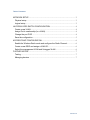
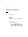
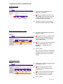
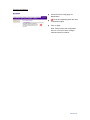
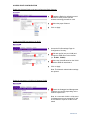
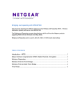
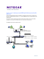
Layer 2 / Layer 3 switches and multi-SSID multi-VLAN network with traffic
separation
This document describes the steps to undertake in configuring a Layer 2/Layer 3 switch (in this
document a FMS7382S with firmware 7.3.1.7) and a WNDAP330 to host a multi-SSID and multiVLAN network.
The solution will allow separating the Wireless traffic and Wired traffic of each of the VLANs
configured, from any other VLAN which will exist on the Wired or Wireless LAN.
2
AN
VL
VL
AN
3
The diagram below shows a typical scenario.
WNDAP330
Management VLAN = 1
Management IP = 192.168.0.235
SSID “VLAN2” (VLAN ID = 2), Open system None
SSID “VLAN3” (VLAN ID = 3), Open system None
LAN to 1/0/6
DGFV338 LAN to 1/0/2
DGFV338
LAN IP: 10.0.0.1/24
DHCP 10.0.0.0/24
LAYER2/LAYER3 SWITCH
VLAN1:
Management IP 192.168.0.254
Port: 1/0/1, 1/0/6, 1/0/7-1/0/28 (Untagged)
VLAN 2:
Ports: 1/0/2, 1/0/3 (PVID = 2, Untagged), 1/0/6 (Tagged)
VLAN 3:
Ports: 1/0/4, 1/0/5 (PVID = 3, Untagged) , 1/0/6 (Tagged)
1/0/4 to LAN
Corporate LAN
Internet
Version 1.0
Table of Contents
NETWORK SETUP.......................................................................................................... 3
Physical setup ............................................................................................................... 3
Logical setup ................................................................................................................. 3
LAYER2/LAYER3 SWITCH CONFIGURATION ......................................................... 4
Create a new VLAN ..................................................................................................... 4
Assign Port’s membership (to a VLAN) .................................................................... 4
Change the port PVID ................................................................................................. 4
Save the configuration ................................................................................................. 5
ACCESS POINT CONFIGURATION ............................................................................ 6
Enable the Wireless Radio mode and configure the Radio Channel ................... 6
Create a new SSID and assign a VLAN ID .............................................................. 6
Select the management VLAN and Untagged VLAN ............................................. 6
FURTHER NOTES........................................................................................................... 7
Testing ........................................................................................................................... 7
Managing devices ........................................................................................................ 7
Version 1.0
NETWORK SETUP
Physical setup
DGFV338 connected to port 1/0/2 on Layer2/Layer3 switch
Corporate LAN connected to port 1/0/4 on Layer2/Layer3 switch
WNDAP330 connected to port 1/0/6 on Layer2/Layer3 switch
Logical setup
DGFV338
LAN IP: 10.0.0.1/24
DHCP: 10.0.0.0/24
WNDAP330
Management VLAN = 1
Untagged VLAN = 1
LAN management IP = 102.168.0.235
SSID VLAN2 (VLAN ID=2), Network authentication (Optional)
SSID VLAN3 (VLAN ID=3), Network authentication (Optional)
Layer2/Layer3 switch
Model: FSM7328S (or any Layer2, Layer3 switch)
Firmware: 7.3.1.7 (or above)
VLAN1
Management IP = 192.168.0.254
Ports = 1/0/1, 1/0/6-1/0/28 (All ports untagged)
VLAN2
Ports = 1/0/2, 1/0/3 (PVID = 2, Untagged), 1/0/6 (Tagged)
VLAN3
Ports = 1/0/4, 1/0/5 (PVID = 3, Untagged), 1/0/6 (Tagged)
Version 1.0
LAYER2/LAYER3 SWITCH CONFIGURATION
Create a new VLAN
Access the VLAN configuration via
Switching, VLAN, Basic.
Input the VLANID, VLAN name and
select static as the VLAN type and click
on Add. Repeat the process for each
VLAN that needs to be created.
The picture shows the summary after
VLAN2 and VLAN3 have been created.
Assign Port’s membership (to a VLAN)
Access the VLAN Membership page via
Switching, VLAN.
Select the relevant VLAN ID and click
on the little arrow symbol beside Unit 1
(this will expand the menu showing the
list of available ports).
Click on the gray area below each port
until the relevant selection is set (U =
Untagged, T = Tagged, Gray = No
selection).
Click on Apply.
Note: The picture shows the membership
settings for VLAN2 as per our scenario.
Repeat the procedure for VLAN 3 and
VLAN1.
Change the port PVID
Access the Port PVID configuration page
via Switching, VLAN.
Set the PVID to the value for the
relevant VLAN (For example VLAN 3
PVID will be 3).
Select the ports that will be assigned
with the above PVID (in our scenario
ports 1/0/4 and 1/0/5 are in VLAN3).
Click on Apply.
Version 1.0
Save the configuration
Access the Save Config page via
Maintenance.
Tick the box appearing within the Save
Configuration option.
Click on Apply.
Note: Failing to Save the configuration
will incur in a loss of all the changes
made should the unit reboot.
Version 1.0
ACCESS POINT CONFIGURATION
Enable the Wireless Radio mode and configure the Radio Channel
Enable the Radio (by default its turned
on under 2.4GHz) for the relevant
wireless technology that will be used.
Select the proper Channel.
Click on Apply
Create a new SSID and assign a VLAN ID
Access the Profile settings Page via
Configuration, Security.
Edit each profile (one per VLAN) and
change the SSID name to be relevant
(i.e. VLAN2 , VLAN3).
Select the VLAN ID based on the VLAN
which the SSID will associate to.
Click on Apply.
Note: The Network authentication settings
are optional.
Select the management VLAN and Untagged VLAN
Ensure the Untagged and Management
VLAN are set correctly depending on the
network requirement.
Note: In our scenario VLAN 1 will be used
for Management as our managing PC will
be connected to a port in VLAN1 on the
switch
Version 1.0
FURTHER NOTES
Testing
Testing can be performed by connecting a Wireless client to each of the SSID alternatively (i.e.
VLAN2, VLAN3) and try to ping a device in the VLAN associate to such SSID.
Ensure the Wireless client obtains an IP address from a DHCP server or hard-code an IP address
relevant to the VLAN the Wireless client will be connecting to.
In this scenario, when connecting to VLAN2, the Wireless client should obtain the TCP/IP settings
from the DGFV338 DHCP server and be able to ping the DGFV338 LAN address; if available the
Wireless client should also be able to access the Internet
Managing devices
DGFV338
The unit will be managed via a device (wired or wireless) connected to VLAN2 only
WNDAP330
The unit will be managed, upon being configured, from a device (wired or wireless)
connected to a port in VLAN1 on the Layer2/Layer3 switch as VLAN 1 is the
management VLAN for the Access Point
Layer2/Layer3 switch
The unit will be managed connecting to a port in VLAN1, as this is the management
VLAN
Version 1.0