1
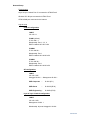
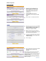
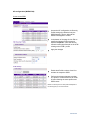
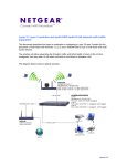
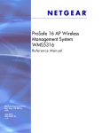
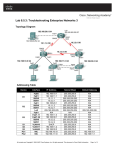
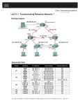
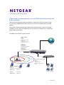
UTM (Unified Threat Management) in a multi-SSID multi-VLAN network with
traffic separation
This document describes the steps to undertake in configuring a UTM 10 (Firmware version
1.0.16-0) and a WNDAP330 (Firmware version 3.0.3) to host a multi-SSID and multi-VLAN
network.
The solution will allow separating the Wireless traffic and Wired traffic of each of the VLANs
configured, from any other VLAN which will exist on the Wired or Wireless LAN – maintaining
same VLAN communication.
The diagram below shows a typical scenario.
UTM 10 Configuration
LAN IP
192.168.1.1
VLAN1 (Corporate - default)
IP 192.168.1.1
Membership: Port 1, 2, 3, 4
DHCP enabled 192.168.1.x/24
Internet
VLAN20 (Guest1)
IP 192.168.20.1
Membership: Port 1
DHCP enabled 192.168.20.x/24
VLAN30 (Engineering)
IP 192.168.30.1
Membership: Port 1
DHCP enabled 192.168.30.x/24
UTM Port 1 to AP LAN
UTM Port 2 to Switch 0/1
Corporate
Guest
Engineering
Layer 2/ Layer 3 switch configuration
LAN IP
192.168.1.239
Management VLAN: 1
Membership : all ports Untagged in
VLAN1
AP configuration (WNDAP330)
LAN IP
192.168.1.235
Untagged VLAN: 1 – Management VLAN: 1
SSID Corporate
–
VLAN 1(ID 1)
SSID Guest
–
VLAN 20 (ID 20)
SSID Engineering –
VLAN30 (ID 30)
Wired LAN 192.168.1.x/24
Version 2.0
Table of Contents
Network Setup .................................................................................................................. 3
Physical setup ............................................................................................................... 3
Logical setup ................................................................................................................. 3
UTM10 Configuration ...................................................................................................... 4
Create a new VLAN ..................................................................................................... 4
AP configuration (WNDAP330) ...................................................................................... 5
Create a new SSID ...................................................................................................... 5
Further Notes .................................................................................................................... 6
Testing ........................................................................................................................... 6
Managing devices ........................................................................................................ 6
Version 2.0
Network Setup
Physical setup
Layer 2/Layer 3 switch Port 0/1 connected to UTM10 Port 2
Wireless AP LAN port connected to UTM10 Port 1
UTM10 WAN port connected to the Internet
Logical setup
UTM 10 Configuration
LAN IP
192.168.1.1
VLAN1 (default)
IP 192.168.1.1
Membership: Port 1, 2, 3, 4
DHCP enabled 192.168.1.x/24
VLAN20
IP 192.168.20.1
Membership: Port 1
DHCP enabled 192.168.20.x/24
VLAN30
IP 192.168.30.1
Membership: Port 1
DHCP enabled 192.168.30.x/24
AP configuration
LAN IP
192.168.1.235
Untagged VLAN: 1 – Management VLAN: 1
SSID Corporate
–
VLAN 1(ID 1)
SSID Guest
–
VLAN 20 (ID 20)
SSID Engineering –
VLAN30 (ID 30)
Layer 2/ Layer 3 switch configuration
LAN IP
192.168.1.239
Management VLAN: 1
Membership: all ports Untagged in VLAN1
Version 2.0
UTM10 Configuration
Create a new VLAN
Access the VLAN configuration via
Network Config, LAN settings, LAN
Setup. VLAN1 exists on the default
configuration and all the ports are
members of it.
Change VLAN1 Profile name to
Corporate by simply editing the VLAN
profile.
Click on Add… to create a new VLAN
Repeat the same process for both VLAN
20 and VLAN 30 (for administration
purposes each will have the profile name
matching the respective SSID).
Port 1 will be the only port member of
each of the new VLANs as this is the port
the Access Point will connect to.
(If required enable DHCP with a scope of
addresses within the same range as the
VLAN IP address).
Click on Apply.
After creating each VLAN the User will be
prompted with the VLAN Profiles
summary
NOTE: Although not relevant in this scenario, attention
should be dedicated to the Default VLAN concept.
Changing the Default VLAN for a Port will be equivalent to
changing the PVID of the port on for example a Netgear
switch 802.1q capable.
A port member of multiple VLANs will be instead be the
equivalent of setting an 802.1q trunk port, as long as the
default VLAN is VLAN 1.
Version 2.0
AP configuration (WNDAP330)
Create a new SSID
Access the AP configuration via Security,
Profile settings (by default all only the
SSID Netgear is active, whilst all the
SSIDs are assigned to VLAN 1
In the bottom of the page click on Edit to
modify the Netgear profile name and
SSID to Corporate – note how this will
reflect the settings performed on the UTM
relating to the VLAN 1 profile
Apply the changes
Enable both Profile numbers 2 and 3 to
activate the respective SSID.
Perform the relevant changes to assign
one profile to VLAN 20 and one to VLAN
30 also reflecting the same profiles and
SSID names
NOTE: The security level on each profile will depend on
the Security policy in use in the network
Version 2.0
Further Notes
Testing
Testing can be performed by connecting a Wireless client to each of the SSID alternatively (i.e.
Corporate, Guest, Engineering) and trying to access the Internet or ping the IP address assigned
to the UTM in the VLAN associated to the SSID.
Ensure the Wireless client obtains an IP address from a DHCP server or hard-code an IP address
relevant to the VLAN the Wireless client will be connecting to.
Inter-VLAN routing will work between VLANs if the following option is enabled in both the source
and destination VLAN:
Managing devices
UTM
The unit will be managed using the IP address configured on the VLAN the
managing device will try to connect from.
The unit will therefore be accessible using 192.168.1.1 in VLAN1, 192.168.20.1 in
VLAN 20 and 192.168.30.1 in VLAN 30.
WNDAP330
The unit will be managed, upon being configured, from a device (wired or wireless)
connected to a port in VLAN1 ,as VLAN 1 is the management VLAN for the Access
Point (IP 192.168.1.235)
Layer2/Layer3 switch
The unit will be managed connecting to a port in VLAN1, as this is the management
VLAN for the switch (192.168.1.239)
Version 2.0