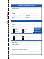
1
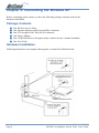
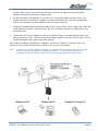
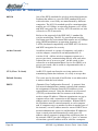
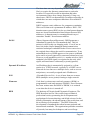
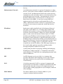
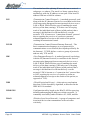
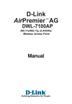
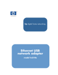
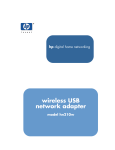
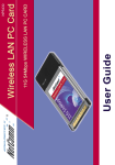
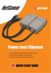
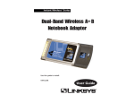
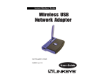
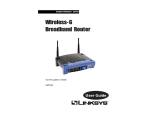
Contents
Chapter 1: Introduction .................................................................................................. 3
The NetComm 11G 54Mbps Wireless Access Point ...................................... 3
Chapter 2: Planning Your Wireless Network ................................................................ 4
Network Topology ............................................................................................ 4
Roaming .......................................................................................................... 4
How to Make Your Wireless Network More Secure ......................................... 5
Chapter 3: Your NetComm 11G Wireless AP ............................................................... 6
The Back Panel ................................................................................................ 6
The Front Panel ............................................................................................... 7
Chapter 4: Connecting the Wireless AP ....................................................................... 8
Package Contents ........................................................................................... 8
Hardware Installation ...................................................................................... 8
Chapter 5: Setting Up the Wireless Access Point ...................................................... 10
Connecting the AP to your Network ...............................................................
Setting Up TCP/IP in Windows ......................................................................
Installing the Wireless Navigator ..................................................................
Startup and Login ..........................................................................................
Configuring the Access Point ........................................................................
Firmware Upgrade Procedure .......................................................................
10
10
13
14
15
22
Appendix A: Troubleshooting ...................................................................................... 23
Frequently Asked Questions ......................................................................... 23
Appendix B: Glossary .................................................................................................. 26
Appendix C: Specifications .......................................................................................... 31
Registering your NetComm Product ........................................................................... 32
Trademarks and Notices ............................................................................................ 32
Warranty Registration Form .......................................................................... 33
Product Warranty ............................................................................................ 35
Limitations of Warranty .................................................................................. 35
www.netcomm.com.au
Page 2
Rev. 1 - YML668
NP5400 11g Wireless Access Point User Guide
Chapter 1: Introduction
The NetComm 11G 54Mbps Wireless Access Point
Congratulations on your purchase of the Netcomm 11G 54Mbps Wireless Access Point (AP).
This product is designed specifically for high-speed wireless LAN environment needs. It is easy
to configure and operate even for non-technical users. Instructions for installing and configuring
this product are included in this manual. Before you install and use this product, please read the
manual carefully so you may take full advantage of its functions.
■ 11g Draft Standards Compliant - The AP complies with IEEE802.11g standard, and it is
interoperable with IEEE802.11g-Compliant Equipment.
■ Interoperable with IEEE802.11b -Backward compatible with IEEE802.11b equipment.
■ Flexible Connectivity - Using external, detachable dipole antenna allows connection of
optional Directional Antenna.
■ Data Rate Auto Fall-Back - Provides 54, 48, 36, 24,12, 11, 9, 6, 5.5, 2 and 1Mbps wireless
data rate shifting dynamically between 11g and 11b to guarantee availability and reliability of
wireless connections.
■ Roaming - Provides seamless roaming within 802.11g and 802.11b wireless LAN
infrastructure.
LAN Features
■ Built-in 10/100M LAN Port - It's designed to connect the AP with any 10/100M LAN Hub/
Switch or router.
■ DHCP Client - Enable the AP to act as a DHCP client to receive IP address from DHCP
Server in the wired Ethernet LAN.
Configuration & Management
■ Easy to Setup - With windows-based Wireless Navigator Utility, user can easily setup the
IP address of this AP, and upgrade the firmware.
■ Easy to manage - User can use any WEB browser from anywhere on the wired or wireless
LAN to configure the AP easily.
Security
■ Configuring Protection - Provides password protection to prevent unauthorized users from
changing the configuration
■ Wireless LAN Security - Provide 64-bit & 128-bit Wired Equivalent Privacy encryption to
protect the wireless data transmissions.
Rev. 1 - YML668
NP5400 11g Wireless Access Point User Guide
www.netcomm.com.au
Page 3
Chapter 2: Planning Your Wireless Network
Network Topology
A wireless LAN is a group of computers, each equipped with one Instant Wireless Series
adapter. Computers in a wireless LAN must be configured to share the same radio channel.
The Instant Wireless Series adapters provide access to a wired LAN for wireless workstations.
An integrated wireless and wired LAN is called an infrastructure configuration. A group of
Instant Wireless Series adapter users and an Instant Wireless 11g Wireless Access Point
compose a Basic Service Set (BSS). Each Instant Wireless Series adapter PC in a BSS can talk to
any computer in a wired LAN infrastructure via the 11g Wireless Access Point.
An infrastructure configuration extends the accessibility of an Instant Wireless Series adapter PC
to a wired LAN, and doubles the effective wireless transmission range for two Instant Wireless
Series adapter PCs. Since the 11g Wireless Access Point is able to forward data within its BSS,
the effective transmission range in an infrastructure LAN is doubled.
Roaming
Infrastructure mode also supports roaming capabilities for mobile users. More than one BSS can
be configured as an Extended Service Set (ESS). This continuous network allows users to roam
freely within an ESS. All PCs equipped with an Instant Wireless Series adapter within one ESS
must be configured with the same ESS ID and use the same radio channel.
Before enabling an ESS with roaming capability, choosing a feasible radio channel and optimum
11g Wireless Access Point position is recommended. Proper Access Point positioning combined
with a clear radio signal will greatly enhance performance.
www.netcomm.com.au
Page 4
Rev. 1 - YML668
NP5400 11g Wireless Access Point User Guide
How to Make Your Wireless Network More Secure
Wireless networks can be vulnerable to an outsider gaining access if the encryption
settings are not set adequately. Some of the default security settings on some wireless
hardware, and in Microsoft Windows, may allow access to your wireless network from
other wireless devices.
The concepts that are presented here are offered only as a guide, and may help make
your wireless network more difficult for an outsider to gain access. For more specific
information about the implementation of these suggestions, you should consult a
trusted security source.
■ Enable Wired Equivalent Privacy (WEP) encryption.
The 802.11 standard, which your NetComm WLAN device is based on, permits Wired
Equivalent Privacy (WEP) encryption. Depending on what other hardware you use, there are
two levels of WEP typically available: 64-bit encryption (based on a 40-bit encryption key),
and 128-bit encryption (based on a 104-bit key). We strongly recommend that you enable
WEP.
■ Change the default Service Set Identifier (SSID) and passwords for your network devices.
Do not change the SSID or password to reflect your name, address, or anything that would
be easy to guess as this could make it easy for an outsider to gain access to your wireless
network.
■ Install Access Points away from windows or building perimeter.
If you are installing access points, think about locating them towards the centre of your site
instead of near the windows. Plan your coverage to radiate out to the windows, but not
beyond. If the access points are located near the windows, a stronger signal will be radiated
outside your home making it easier for those outside the building to locate your network.
■ Check the range of your network.
Take a notebook, or a PDA computer, that is equipped with a wireless network PC Card and
go outside your home to survey what range you get when moving around your property or
neighbourhood. You may be surprised how far the signal radiates. If you can connect beyond
the perimeter of your property, so can someone else.
■ Disable the Beacon.
If possible, disabling the beacon will make it harder for hackers to locate and identify your
network.
■ Use a combination of the previous suggestions.
Rev. 1 - YML668
NP5400 11g Wireless Access Point User Guide
www.netcomm.com.au
Page 5
Chapter 3: Your NetComm 11G Wireless AP
The Back Panel
Antenna Connection
INIT Button
Selection Switch
LAN Cable
Power Input
Antenna Connection
Please install the external dipole antenna directly into the reversed SMA connector of AP. After
the AP starts to work, you may adjust the angle of the antenna or reposition the AP to get a
better performance and reach.
INIT Button
“INIT” means “Initiation”. While pressing the button, the AP will reboot and ERASE all current
settings, and restore to factory default settings. The left indicator “DIAG” on the AP will at
first be off and then begin blinking. The initiation procedure will be completed when the
indicator “DIAG” returns to being always on and green.
LAN Cable
Selection Switch
X Crossover:
the RJ-45 port Tx and Rx lines are reversed. Use this setting
when you use the supplied UTP straight cable connected to
PC.
II Straight:
the RJ-45 port Tx and Rx lines are normal. Use this setting
when you have the supplied UTP straight cable connected to
Hub/Switch or Router. It is also the factory default setting.
Power Input
Only use the power adapter supplied with the Access Point LAN Connection
Important: Resetting the Access Point will erase all of your settings (WEP Encryption,
Wireless and LAN settings, etc.) and replace them with the factory defaults. Do not
reset the Access Point if you want to retain these settings
www.netcomm.com.au
Page 6
Rev. 1 - YML668
NP5400 11g Wireless Access Point User Guide
The Front Panel
LED
Color
Status
Description
Power
Green
ON
The AP power on
OFF
The AP power off
ON
1) The AP is in normal operation mode
2) While in firmware upgrade process, it indicates
the AP is writing the firmware into Flash ROM
Blinking
1) The AP is in self-diagnostic mode.
2) While in firmware upgrade process, it indicates
the AP is waiting the Wireless Navigator sending
firmware image
OFF
1) The AP starts to boot up the system.
2) While in firmware upgrade process, it
indicates the firmware upgrade process is
finished.
ON
The LAN port has a successful physical link.
Blinking
Sending or receiving data
OFF
No connection, and neither data forwarding from
LAN ports.
ON
Wireless port is connected with another wireless
device(s) successfully
OFF
Wireless port is not connected to any device.
Blinking
Sending or Receiving data via wireless
DIAG
LAN
WLAN
Green
Green
Green
Rev. 1 - YML668
NP5400 11g Wireless Access Point User Guide
www.netcomm.com.au
Page 7
Chapter 4: Connecting the Wireless AP
Before continuing, please ensure you have the following package contents ready for the
hardware installation.
Package Contents
■
■
■
■
■
■
One Wireless Access Point
One External Antenna with Reversed SMA Connector
One UTP straight LAN Cable (RJ-45 connector)
One Power Adapter
One CD-ROM (Wireless Navigator utility software & user’s manual included)
One User Guide
Hardware Installation
Following illustration is an example showing how to install AP with hub/switch.
www.netcomm.com.au
Page 8
Rev. 1 - YML668
NP5400 11g Wireless Access Point User Guide
1. Find an optimum location for the Access Point. The best place for the Access Point is
usually at the center of your wireless network, with line of sight to all of your mobile
stations. Placing the unit in the celing is ideal.
2. Fix the direction of the antenna. Try to place it in a position which can best cover your
wireless network. Normally, the higher you place the antenna, the better the performance
will be. The antenna's position enhances the receiving sensitivity.
3. Connect a standard Ethernet network cable to the Access Point. Then, connect the other end
of the Ethernet cable to a switch or hub. The Access Point will then be connected to your
wired Network.
4. Connect the AC Power Adapter to the Access Point's Power port and plug the other end
into an electrical outlet. Only use the power adapter supplied with the Access Point. Use of
a different adapter may result in product damage.
Now that the hardware installation is complete, proceed to Chapter 5: Setting Up the 11g
Wireless Access Point for directions on how to set up the Access Point.
Note:
In order for all other wireless devices to communicate with the Access Point, those
devices must be operating in Infrastructure Mode. If any wireless devices are
configured in Ad Hoc Mode, they will not be recognized by the Access Point.
Rev. 1 - YML668
NP5400 11g Wireless Access Point User Guide
www.netcomm.com.au
Page 9
Chapter 5: Setting Up the Wireless Access Point
Connecting the AP to your Network
For optimal performance, usually the center of your wireless network is the best place for your
AP, with line of sight to all of your mobile stations. Try to place it in a position where can best
cover your wireless network and is away from any potential source of interference. And
normally, the higher you place the AP, the better the wireless signal coverage will be.
The following picture describes how to use the AP when communicating between wireless LAN
and wired LAN.
Setting Up TCP/IP in Windows
Before a computer can communicate with the Access Point, it must be configured with the TCP/
IP protocol. If you know how to set up TCP/IP on your computers, do so now. Otherwise, use
the guidelines below to help get TCP/IP installed on all of the computers that need to
communicate with the Access Point. If you are unable to successfully install TCP/IP on one or
more computers after following the directions, contact the manufacturer of your computers'
network operating system for further assistance. Check with your network administrator for
your TCP/IP settings.
The directions below provide general guidelines for coming up with IP addresses and subnet
masks. Check with your network administrator to see if you need to use specific IP addresses or
DHCP settings.
First, each computer on the network will require an IP address, which is a series of numbers,
separated by periods, identifying the PC on the network. To make things simple, you should use
the following numbering scheme:
192.168.1.X
In this example, X is a unique, arbitrarily assigned number from 1 to 254. Each computer must
have its own unique X number. Note: Never use 0, 250 or 255 for X. These numbers are
reserved by TCP/IP for other uses.
Each computer will also require a subnet mask, which is a numerical "filter" that tells a computer
what kinds of TCP/IP data packets to accept. If you're not sure which mask to use, the
following mask is recommended:
255.255.255.0
The following instructions are provided as examples for reference only. For complete
instructions on installing and troubleshooting TCP/IP please consult your Windows operating
system documentation.
www.netcomm.com.au
Page 10
Rev. 1 - YML668
NP5400 11g Wireless Access Point User Guide
TCP/IP Setup for Windows 98 and Millennium
1. Click the Start button, select Settings, and open the Control Panel. Inside the Control Panel,
double-click the Network icon.
2. If the TCP/IP Protocol is listed for your network adapter, go to step five. Otherwise, click
the Add button.
3. When the Component Type window appears, select Protocol and click the Add button.
4. Select Microsoft in the Manufacturers list and choose TCP/IP in the Network Protocols list.
Then, click the OK button.
5. When the Network window reappears, click TCP/IP. Then, click the Properties button.
6. Select Specify an IP Address.
7. Enter an IP Address for the computer, along with a Subnet Mask. Click the OK button. If
you do not have these values, consult your network administrator.
8. When the Network window reappears, click the OK button. Restart your machine. TCP/IP
has now been successfully installed.
TCP/IP Setup for Windows NT4.0
1. Click the Start button, select Settings, and open the Control Panel. Inside the Control Panel,
double-click the Network icon.
2. When the Network window appears, click the Protocols tab. Then, click the Add button.
3. Find the TCP/IP protocol in the Select Network Protocol field. Click it once and then click
the OK button.
4. When asked if you want to use DHCP, choose No.
5. If asked to supply your Windows NT CD, do so. NT will copy the necessary files to your
system. You may have to switch between the Access Point's Setup CD and the NT CD.
6. When TCP/IP appears in the Network Protocols window, click the Bindings tab. Windows
will store your new bindings.
7. Click the Protocols tab. Then, select TCP/IP.
8. Click the Properties button. Select the type of network adapter you have from the Adapters
box and select Specify an IP Address.
9. Enter the computer's IP Address and Subnet Mask. Check with your network administrator
for your settings.
10. Enter your Default Gateway if you have one.
Note: a Default Gateway is not required. Check with your network administrator.
11. When you finish, click the OK button. If NT asks about WINS, ignore it.
12. When the Network window reappears, click the Close button. Restart your computer when
prompted. TCP/IP has now been successfully installed.
Rev. 1 - YML668
NP5400 11g Wireless Access Point User Guide
www.netcomm.com.au
Page 11
TCP/IP Setup for Windows 2000
1. At the Windows 2000 desktop, right click My Network Places and select Properties. Then,
right click Local Area Connection. Choose Properties.
2. If the TCP/IP Protocol is listed for your network adapter, go to step five. Otherwise, click
the Install button.
3. When the Component Type window appears, select Protocol, and click the Add button.
4. Select Internet Protocol (TCP/IP) from the list and click the OK button.
5. When the Local Area Connection Properties window reappears, select TCP/IP, and click the
Properties button.
6. Select Use the following IP Address.
7. Enter an IP Address for the computer, along with a Subnet Mask and Default Gateway.
Then, click the OK button. If you do not have these values, consult your network
administrator.
8. When the Local Area Connection Properties window reappears, click the OK button. TCP/
IP has now been successfully installed.
TCP/IP Setup for Windows XP
1. Click the Start button and open the Control Panel.
2. Double click the Network and Internet Connections icon.
3. Double click the Network Connections icon.
4. Right click the Local Area Connection icon and select Properties.
5. If the TCP/IP Protocol is listed for your network adapter, go to step five. Otherwise, click
the Install button.
6. When the Component Type window appears, select Protocol, and click the Add button.
7. Select Internet Protocol (TCP/IP) from the list and click the OK button.
8. When the Local Area Connection Properties window reappears, select TCP/IP, and click the
Properties button.
9. Select Use the following IP Address.
10. Enter an IP Address for the computer, along with a Subnet Mask and Default Gateway.
Then, click the OK button. If you do not have these values, consult your network
administrator.
11. When the Local Area Connection Properties window reappears, click the OK button. TCP/
IP has now been successfully installed.
www.netcomm.com.au
Page 12
Rev. 1 - YML668
NP5400 11g Wireless Access Point User Guide
Installing the Wireless Navigator
The Wireless Navigator Utility is provided to allow user(s) easily to configure the AP through
any Windows-based PC over wired or wireless LAN port. This section describes procedures for
installing the Wireless Navigator Utility to PC.
1. Insert the installation CD-ROM into the CD-ROM drive. Run SETUP.EXE program on the
CD-ROM.
2. After the InstallShield Wizard preparation has completed finished, the Install Shield window
will be shown. Click the Next button to continue.
3. Key in your User Name and Company Name, and click Next button to continue.
4. The screen will show you the default destination chosen by the utility. If you wish to install
the Wireless Navigator in another location, click the Browse button and select an alternate
destination. Click the Next button when you are ready to continue. The setup program will
then begin to install the programs into the destination folder.
5. The screen will show you the Program Folder that the utility will use. You may type a new
folder name to create a new program folder, or select one from the existing folder list, and
click Next button to continue.
6. The Wireless Navigator has been installed now. Please click the Finish button to complete
installation.
Note:
To remove Wireless Navigator Utility, click the Start button, and select Programs,
Wireless Navigator, and Uninstall, and then follow the instruction on screen.
Rev. 1 - YML668
NP5400 11g Wireless Access Point User Guide
www.netcomm.com.au
Page 13
Startup and Login
Follow the procedures below to startup Wireless Navigator and find the AP. Before you start
the following procedure, please connect the Ethernet cable, connect the power cord, and then
turn on the AP. All wireless clients should be requested to set the their SSIDs to the same as the
AP SSID in advance before continuing.
1. Refer to previous section "Install the Wireless Navigator to your PC" in order to startup the
configuration.
2. Click Start and select Programs, Wireless Navigator and then Wireless Navigator. Or, just
double-click the Wireless Navigator icon on your desktop screen.
3. The Wireless Navigator starts up, and searches AP via wired LAN or Wireless LAN.
4. The utility will show the AP and any other wireless devices found in the same network.
Note!
If the AP is not shown in the list, please make sure all the cables are well
connected.
5. Double-click on the AP device to access the built-in web server. The User Name and
Password screen will be displayed. The default setting is no user name and the password is
"admin". Click OK to continue.
Note!
If you cannot access into AP's built-in web server, please make sure if your PC now
is in the same subnet with AP. Please us right-click of mouse to click on the AP
listed in Wireless Navigator. "Set IP address" option will pop out, and then change
IP address of AP to the same subnet as your PC.
6. Now you have entered the built-in web server of this AP, you can begin configuration
procedures.
www.netcomm.com.au
Page 14
Rev. 1 - YML668
NP5400 11g Wireless Access Point User Guide
Configuring the Access Point
The Wireless Navigator includes nine tabs to help you customise your Access Point settings to
fit your Network:
■
the Info tab
■
the Assoc tab
■
the Wireless tab
■
the Access tab
■
the Advanced tab
■
the Security tab
■
the IP Address tab
■
the Admin tab
■
the Help tab
Rev. 1 - YML668
NP5400 11g Wireless Access Point User Guide
www.netcomm.com.au
Page 15
The Info Tab
The Info Tab displays the current AP settings.
Access Point Information
Access point name:
Displays current device name of the AP. You also can change
the name.
MAC address of AP:
Displays the unique fMAC number burned into this AP that
identifies itself from other Ethernet devices
Associated stations:
Displays the number of wireless client devices associated
with this AP.
Wireless Firmware version:
Displays the version number of wireless LAN firmware
embedded in this AP.
AP version:
Displays the version number of AP system firmware.
Current IP settingsIP address:
Displays the current IP address of this AP.
DHCP client:
Displays if this AP enable DHCP client feature or not.
Current Wireless
SettingsPerformance Mode:
Displays the AP is set in Maximum interoperability mode or
Maximum performance mode.
Wireless network name (SSID):
Displays current SSID of the AP. Please make sure that
your wireless LAN is working properly under the effective
reach range of the AP
WEP:
Displays the WEP function is enabled or disabled.
www.netcomm.com.au
Page 16
Rev. 1 - YML668
NP5400 11g Wireless Access Point User Guide
The Assoc Tab
The Assoc Tab displays all the wireless clients, which are currently associated with this AP.
Mac address:
Displays the list of the MAC address of associated wireless
client.If you click the refresh button of your web browser,
then the list will be updated.
The Wireless Tab
The Wireless Tab lets you select the network settings.
Performance Mode:
In Maximum interoperability mode, the AP will accept
connections to both 802.11b and 802.11g client devices. In
Maximum performance mode, the AP will only connect to
802.11g client devices for better performance.
Wireless Network Name (SSID):
Lets you set the Service Set Identification. Default SSID is
"wireless". This should be changed to some thing nondescriptive.
Channel:
Enables you to select a transmission channel. This setting
only works in infrastructure mode.
Transmission Rate:
Select transfer rate from an available list.
Note:
Click button "Save" to store the settings. The settings will work after AP
automatically reboots.
Rev. 1 - YML668
NP5400 11g Wireless Access Point User Guide
www.netcomm.com.au
Page 17
The Access Tab
The Access Tab allows you to set the filter to specific wireless client device(s).
Enable access control:
If it is checked, the AP will start to filter any wireless client
device with MAC address listed below.
MAC address #:
Please enter the MAC address of the wireless devices which
need filtered in wireless LAN network. The device with same
MAC address listed will not be able to associate with this
AP.
Note:
Click button "Save" to store the settings. The settings will work after AP
automatically reboots.
The Advanced Tab
The Advanced Tab allows you to configure advanced 802.11 settings
Preamble type:
Enables to select different preamble types: Long, Short or
Auto. While Short type is selected, the performance may be
improved with the possibility of incompatibility
Max associated stations:
Enables to set the limit of the maximum number of associated
clients. In order to get a better performance, it is suggested to
set "8" as the maximum number of associated clients to get a
balanced performance
Fragmentation threshold:
The threshold which a data packet will be fragmented.RTS
threshold: The threshold which a RTS packet will be sent
before a data packet is sent.
Beacon period:
The period in millisecond a beacon will be sent.DTIM
interval: Number of beacon intervals between successive
DTIM (Delivery Traffic Identification Maps).
Note:
Click button "Save" to store the settings. The settings will work after AP
automatically reboots.
www.netcomm.com.au
Page 18
Rev. 1 - YML668
NP5400 11g Wireless Access Point User Guide
The Security Tab
The Security Tab displays 802.11b/g security and encryption options on this AP.
WEP configuration:
Display the Wired Equivalent Privacy security
configurations
Enable WEP:
Enables the Wired Equivalent Privacy security function.
WEP key length:
Selects 64-bit or 128-bit WEP encryption. Be sure that the
key length setting in the AP shall be the same as in wireless
clients, or the communication will not work.
WEP key:
For 64-bit WEP encryption, a key of 10 hexadecimal
characters in length must be filled in. For 128-bit WEP
encryption, a key of 26 hexadecimal characters in length
must be filled in. Be sure that the key values in the AP shall
be the same as in wireless clients, or the communication will
not work.
Default WEP key to use:
Selects one of four key sets to be used for encryption. To
connect to a Wi-Fi compliant wireless device, key #1 must
be selected.
Deny unencrypted data:
Check this box, then any unencrypted data frames will be
denied.
Authentication:
Selects the mechanism of Open, Shared key, or both
authentication algorithms.
Firmware upgrading:
To control firmware upgrade
Allow upgrade uploads:
If the box is checked, then users can use utility or any TFTP
program to upgrade the firmware.
Note:
Click button "Save" to store the settings. The settings will work after AP
automatically reboots.
Rev. 1 - YML668
NP5400 11g Wireless Access Point User Guide
www.netcomm.com.au
Page 19
The IP Address Tab
The IP Address Tab displays IP settings options on this AP.
IP Address Mode:
Select "Static" or "DHCP" mode. For "Static" mode, the IP
address settings are given by user. For "DHCP" mode, these
settings will be overridden by a DHCP server on your
network. The default setting is "Static"
Default IP Address:
The static IP address you want to assign to the AP. The
default value is "192.168.1.100".
Default subnet mask:
The subnet mask you want to assign for the AP. The default
value is "255.255.255.0".
Default gateway:
The internet gateway you want to assign for the AP. The
default value is "192.168.1.1".
Access point name:
With the name, the AP can be found easily via Wireless
Nevigator Utility. It can be the nickname assigned by the
adminstrator.
Note:
Click button "Save" to store the settings. The settings will work after AP
automatically reboots.
www.netcomm.com.au
Page 20
Rev. 1 - YML668
NP5400 11g Wireless Access Point User Guide
The Admin Tab
The Admin Tab allows to change the device's system configurations.
Access point name:
With this unque name, the AP can be found easily via
Wireless Nevigator Utility. It can be the nickname assigned
by the adminstrator.
User name:
This is the name used for login into the AP's built Web User
Interface.
Administrator password:
Please key the same password in both columns, then click
"Save" to validate the new password
Commands
Reboot access point:
When any setting was changed, the AP MUST be reboot so
that the change can be confirmed.
Reset to factory defaults:
This option will ERASE all the current settings, and return
back to the factory defaults.
Note:
Click button "Save" to store the settings. The settings will work after AP
automatically reboots.
The Help Tab
The Help Tab displays the explanations of each setting shown in above seven tabs.Please click
those hyperlinks in right side, and then it will direct you the meaning of each setting.
Rev. 1 - YML668
NP5400 11g Wireless Access Point User Guide
www.netcomm.com.au
Page 21
Firmware Upgrade Procedure
1. Click Start and select Programs, Wireless Navigator and then Wireless Navigator. Or, just
double-click the Wireless Navigator icon on your desktop screen.
2. The Wireless Navigator starts up.
3. The computer starts searching for the Access Point and shows in the list. Choose the AP
that you would like to upgrade the firmware, and use the right-click of the mouse to enter the
"Upgrade FW" option
4. The download will begin. Key in the new firmware file name and location or click browsing
to find the file in your computer.
5. After entering the file information, click OK to continue.
6. The downloading begins.
7. After download finished, the AP will reset automatically, and the left indicator "DIAG" on
AP will be off and then begin flashing. When the indicator " DIAG" is always green instead
of blinking, the firmware upgrade is completed and successfully.
www.netcomm.com.au
Page 22
Rev. 1 - YML668
NP5400 11g Wireless Access Point User Guide
Appendix A: Troubleshooting
This section provides solutions to problems usually encountered during the installation and
operation of the Access Point.
Frequently Asked Questions
Can the Access Point act as my DHCP Server?
No. The Access Point is nothing more than a wireless hub, and as such cannot be configured to
handle DHCP capabilities.
Can I run an application from a remote computer over the wireless network?
This will depend on whether or not the application is designed to be used over a network.
Consult the application's user guide to determine if it supports operation over a network.
Can I play multiplayer games with other users of the wireless network?
Yes, as long as the game supports multiple players over a LAN (local area network). Refer to the
game's user guide for more information.
What are Ad-hoc and Infrastructure modes?
An Ad-hoc wireless LAN is a group of computers, each with a WLAN adapter, connected as an
independent wireless LAN. An Ad-hoc wireless LAN is applicable when no AP is available or
you wish to run a private network not joined to the corporate network.
An integrated wireless and wired LAN is called an Infrastructure configuration. Infrastructure is
applicable to enterprise scale for wireless access to a wired network via an AP.
What is Roaming?
Roaming is the ability of a portable computer user to communicate continuously while moving
freely throughout an area greater than that covered by a single Access Point. Before using the
roaming function, the workstation must make sure that it is the same channel number as the
Access Point of the dedicated coverage area.
To achieve true seamless connectivity, the wireless LAN must incorporate a number of different
functions. Each node and Access Point, for example, must always acknowledge receipt of each
message. Each node must maintain contact with the wireless network even when not actually
transmitting data. Achieving these functions simultaneously requires a dynamic RF networking
technology that links Access Points and nodes. In such a system, the user's end node undertakes
a search for the best possible access to the system. First, it evaluates such factors as signal
strength and quality, as well as the message load currently being carried by each Access Point
and the distance of each Access Point to the wired backbone. Based on that information, the
node next selects the right Access Point and registers its address. Communications between end
node and host computer can then be transmitted up and down the backbone.
As the user moves on, the end node's RF transmitter regularly checks the system to determine
whether it is in touch with the original Access Point or whether it should seek a new one. When
a node no longer receives acknowledgment from its original Access Point, it undertakes a new
search. Upon finding a new Access Point, it then re-registers, and the communication process
continues.
Rev. 1 - YML668
NP5400 11g Wireless Access Point User Guide
www.netcomm.com.au
Page 23
What is BSS ID?
A specific Ad-hoc LAN is called a Basic Service Set (BSS). Computers in a BSS must be
configured with the same BSS ID.
What is ESSID?
An Infrastructure configuration could also support roaming capability for mobile workers. More
than one BSS can be configured as an Extended Service Set (ESS). Users within an ESS could
roam freely between BSSs while maintaining a continuous connection to the wireless network
stations and Access Points.
What is ISM band?
The FCC and their counterparts outside of the U.S. have set aside bandwidth for unlicensed use
in the ISM (Industrial, Scientific and Medical) band. Spectrum in the vicinity of 2.4 GHz, in
particular, is being made available worldwide. This presents a truly revolutionary opportunity
to place convenient high speed wireless capabilities in the hands of users around the globe.
What is Spread Spectrum?
Spread Spectrum technology is a wideband radio frequency technique developed by the military
for use in reliable, secure, mission-critical communications systems. It is designed to trade off
bandwidth efficiency for reliability, integrity, and security. In other words, more bandwidth is
consumed than in the case of narrowband transmission, but the trade-off produces a signal that
is, in effect, louder and thus easier to detect, provided that the receiver knows the parameters of
the spread-spectrum signal being broadcast. If a receiver is not tuned to the right frequency, a
spread-spectrum signal looks like background noise. There are two main alternatives, Direct
Sequence Spread Spectrum (DSSS) and Frequency Hopping Spread Spectrum (FHSS).
What is DSSS? What is FHSS? And what are their differences?
Frequency Hopping Spread Spectrum (FHSS) uses a narrowband carrier that changes frequency
in a pattern that is known to both transmitter and receiver. Properly synchronized, the net effect
is to maintain a single logical channel. To an unintended receiver, FHSS appears to be shortduration impulse noise. Direct Sequence Spread Spectrum (DSSS) generates a redundant bit
pattern for each bit to be transmitted. This bit pattern is called a chip (or chipping code). The
longer the chip, the greater the probability that the original data can be recovered. Even if one or
more bits in the chip are damaged during transmission, statistical techniques embedded in the
radio can recover the original data without the need for retransmission. To an unintended
receiver, DSSS appears as low power wideband noise and is rejected (ignored) by most
narrowband receivers.
Would the information be intercepted while transmitting on air?
WLAN features two-fold protection in security. On the hardware side, as with Direct Sequence
Spread Spectrum technology, it has the inherent security feature of scrambling. On the software
side, the WLAN series offers the encryption function (WEP) to enhance security and access
control. Users can set it up depending upon their needs.
www.netcomm.com.au
Page 24
Rev. 1 - YML668
NP5400 11g Wireless Access Point User Guide
What is WEP?
WEP is Wired Equivalent Privacy, a data privacy mechanism based on a shared-key algorithm, as
described in the IEEE 802.11 standard.
What is a MACAddress?
The Media Access Control (MAC) address is a unique number assigned by the manufacturer to
any Ethernet networking device, such as a network adapter, that allows the network to identify
it at the hardware level. For all practical purposes, this number is usually permanent. Unlike IP
addresses, which can change every time a computer logs on to the network, the MAC address of
a device stays the same, making it a valuable identifier for the network.
How do I avoid interference?
Using multiple Access Points on the same channel and in close proximity to one another will
generate interference. When employing multiple Access Points, be sure to operate each one on a
different channel (frequency).
How do I reset the Access Point?
Press the Reset button on the back of the Access Point for about ten seconds. This will reset the
unit to its default settings.
How do I resolve issues with signal loss?
There is no way to know the exact range of your wireless network without testing. Every
obstacle placed between an Access Point and wireless PC will create signal loss. Leaded glass,
metal, concrete floors, water and walls will inhibit the signal and reduce range. Start with your
Access Point and your wireless PC in the same room and move it away in small increments to
determine the maximum range in your environment.
You may also try using different channels, as this may eliminate interference affecting only one
channel. Also, due to FCC regulations, more power may be transmitted, using 802.11a, on
channels 52, 56, 60 and 64, than on the lower channels. Lastly, check the Advanced tab of the
Web-Based Utility and make sure that FULL is selected in the Transmission Rate field.
Does the Access Point function as a firewall?
No. The Access Point is only a bridge from wired Ethernet to wireless clients.
I have excellent signal strength,but I cannot see my network.
WEP is probably enabled on the Access Point, but not on your wireless adapter (or vice versa).
Verify that the same WEP Keys and levels (64 or 128 ) are being used on all nodes on your
wireless network. Also we suggest you check for MAC filtering.
What is the maximum number of users the Access Point facilitates?
No more than 65, but this depends on the volume of data and may be less if many users create a
large amount of network traffic.
How many channels/frequencies are available with the Access Point?
Using 802.11b or 802.11g, there are eleven available channels, ranging from 1 to 11.
Rev. 1 - YML668
NP5400 11g Wireless Access Point User Guide
www.netcomm.com.au
Page 25
Appendix B: Glossary
802.11b
One of the IEEE standards for wireless networking hardware.
Products that adhere to a specific IEEE standard will work
with each other, even if they are manufactured by different
companies. The 802.11b standard specifies a maximum data
transfer rate of 11Mbps, an operating frequency of 2.4GHz,
and WEP encryption for security. 802.11b networks are also
referred to as Wi-Fi networks.
802.11g
Refers to the proposed of the IEEE 802.11 standard for
wireless networking. The 802.11g specifications used by
NetComm specifies a maximum data transfer rate of 54Mbps
using OFDM modulation, an operating frequency of
2.4GHz, backward compatibility with IEEE 802.11b devices
and WEP encryption for security.
Ad-hoc Network
An ad-hoc network is a group of computers, each with a
wireless adapter, connected as an independent 802.11
wireless LAN. Ad-hoc wireless computers operate on a
peer-to-peer basis, communicating directly with each other
without the use of an access point. Ad-hoc mode is also
referred to as an Independent Basic Service Set (IBSS) or as
peer-to-peer mode, and is useful at a departmental scale or
SOHO operation.
CTS (Clear To Send)
An RS-232 signal sent from the receiving station to the
transmitting station that indicates it is ready to accept data.
Default Gateway
The router used to forward all traffic that is not addressed to
a station within the local subnet.
DHCP
(Dynamic Host Configuration Protocol) - A protocol that
lets network administrators manage centrally and automate
the assignment of Internet Protocol (IP) addresses in an
organization's network. Using the Internet's set of protocol
(TCP/IP), each machine that can connect to the Internet
needs a unique IP address. When an organization sets up its
computer users with a connection to the Internet, an IP
address must be assigned to each machine. Without DHCP,
the IP address must be entered manually at each computer
and, if computers move to another location in another part of
the network, a new IP address must be entered. DHCP lets a
network administrator supervise and distribute IP addresses
from a central point and automatically sends a new IP
address when a computer is plugged into a different place in
the network. DHCP uses the concept of a "lease" or amount
of time that a given IP address will be valid for a computer.
www.netcomm.com.au
Page 26
Rev. 1 - YML668
NP5400 11g Wireless Access Point User Guide
The lease time can vary depending on how long a user is
likely to require the Internet connection at a particular
location. It's especially useful in education and other
environments where users change frequently. Using very
short leases, DHCP can dynamically reconfigure networks in
which there are more computers than there are available IP
addresses.
DHCP supports static addresses for computers containing
Web servers that need a permanent IP address. DNS - The
domain name system (DNS) is the way that Internet domain
name are located and translated into Internet Protocol (IP)
addresses. A domain name is a meaningful and easy-toremember "handle" for an Internet address.
DSSS
(Direct-Sequence Spread Spectrum) - DSSS generates a
redundant bit pattern for all transmitted data. This bit
pattern is called a chip (or chipping code). Even if one or
more bits in the chip are damaged during transmission,
statistical techniques embedded in the receiver can recover
the original data without the need for retransmission. To an
unintended receiver, DSSS appears as low power wideband
noise and is rejected (ignored) by most narrowband receivers.
However, to an intended receiver (i.e. another wireless LAN
endpoint), the DSSS signal is recognized as the only valid
signal, and interference is inherently rejected (ignored).
Dynamic IP Address
An IP address that is automatically assigned to a client
station in a TCP/IP network, typically by a DHCP server.
Network devices that serve multiple users, such as servers
and printers, are usually assigned static IP addresses.
ESS
(Extended Service Set) - A set of more than two or more
BSSs (multiple access points) forming a single network.
Firmware
Code that is written onto read-only memory (ROM) or
programmable read-only memory (PROM). Once firmware
has been written onto the ROM or PROM, it is retained
even when the device is turned off.
IEEE
The Institute of Electrical and Electronics Engineers. The
IEEE describes itself as "the world's largest technical
professional society-promoting the development and
application of electrotechnology and allied sciences for the
benefit of humanity, the advancement of the profession, and
the wellbeing of our members." The IEEE fosters the
development of standards that often become national and
international standards. The organization publishes a number
of journals, has many local chapters, and several large
Rev. 1 - YML668
NP5400 11g Wireless Access Point User Guide
www.netcomm.com.au
Page 27
societies in special areas, such as the IEEE Computer
Society.
Infrastructure Network
An infrastructure network is a group of computers or other
devices, each with a wireless adapter, connected as an 802.11
wireless LAN. In infrastructure mode, the wireless devices
communicate with each other and to a wired network by first
going through an access point. An infrastructure wireless
network connected to a wired network is referred to as a
Basic Service Set (BSS). A set of two or more BSS in a
single network is referred to as an Extended Service Set
(ESS). Infrastructure mode is useful at a corporation scale,
or when it is necessary to connect the wired and wireless
networks.
IP Address
In the most widely installed level of the Internet Protocol
(IP) today, an IP address is a 32-binary digit number that
identifies each sender or receiver of information that is sent
in packet across the Internet. When you request an HTML
page or send e-mail, the Internet Protocol part of TCP/IP
includes your IP address in the message (actually, in each of
the packets if more than one is required) and sends it to the
IP address that is obtained by looking up the domain name in
the Uniform Resource Locator you requested or in the e-mail
address you're sending a note to. At the other end, the
recipient can see the IP address of the Web page requester or
the e-mail sender and can respond by sending another
message using the IP address it received.
IPCONFIG
A utility that provides for querying, defining and managing
IP addresses within a network. A commonly used utility,
under Windows NT and 2000, for configuring networks with
static IP addresses.
ISP
An ISP (Internet service provider) is a company that
provides individuals and companies access to the Internet
and other related services such as Web site building and
virtual hosting.
LAN
A local area network (LAN) is a group of computers and
associated devices that share a common communications line
and typically share the resources of a single processor or
server within a small geographic area (for example, within an
office building).
MACAddress
The MAC (Media Access Control) address is your
computer's unique hardware number.
www.netcomm.com.au
Page 28
Rev. 1 - YML668
NP5400 11g Wireless Access Point User Guide
mIRC
mIRC runs under Windows and provides a graphical
interface for logging onto IRC servers and listing, joining and
leaving channels.
Network Mask
also known as the "Subnet Mask."
OFDM
Developed for wireless applications, Orthogonal Frequency
Division Multiplexing (OFDM) technology offers superior
performance-increased data rates and more reliable
transmissions-than previous technologies, such as DSSS.
OFDM is a scheme in which numerous signals of different
frequencies are combined to form a single signal for
transmission on the medium. OFDM works by breaking one
high-speed data stream into a number of lower-speed data
streams, which are then transmitted in parallel. Each lower
speed stream is used to modulate a subcarrier. Essentially,
this creates a multi-carrier transmission by dividing a wide
frequency band or channel into a number of narrower
frequency bands or sub-channels. OFDM is also used for
other applications, including powerline networking.
Plug-and-Play
The ability of a computer system to configure expansion
boards and other devices automatically without requiring the
user to turn off the system during installation.
Roaming
In an infrastructure mode wireless network, this refers to the
ability to move out of one access point's range and into
another and transparently reassociate and reauthenticate to
the new access point. This reassociation and
reauthentication should occur without user intervention and
ideally without interruption to network connectivity. A
typical scenario would be a location with multiple access
points, where users can physically relocate from one area to
another and easily maintain connectivity.
SSID
(Service Set Identifier) - An identification name that wireless
devices use to make connections. In order for wireless
devices to communicate, they must all be set to the same
channel and they all must use the same SSID. For instance, if
you are using an access point to connect two computers
using wireless devices, the access point and each of the
wireless devices must use the same SSID. Even if they are
set to the same channel, they cannot communicate unless the
SSID is the same.
Static IP Address
A permanent IP address that is assigned to a node in a TCP/
IP network.
Rev. 1 - YML668
NP5400 11g Wireless Access Point User Guide
www.netcomm.com.au
Page 29
Subnet Mask
The method used for splitting IP networks into a series of
subgroups, or subnets. The mask is a binary pattern that is
matched up with the IP address to turn part of the host ID
address field into a field for subnets.
TCP
(Transmission Control Protocol) - A method (protocol) used
along with the IP (Internet Protocol) to send data in the form
of message units (datagram) between network devices over a
LAN or WAN. While IP takes care of handling the actual
delivery of the data (routing), TCP takes care of keeping
track of the individual units of data (called packets) that a
message is divided into for efficient delivery over the
network. TCP is known as a "connection oriented" protocol
due to requiring the receiver of a packet to return an
acknowledgment of receipt to the sender of the packet
resulting in transmission control.
TCP/IP
(Transmission Control Protocol/Internet Protocol) - The
basic communication language or set of protocols for
communications over a network (developed specifically for
the Internet). TCP/IP defines a suite or group of protocols
and not only TCP and IP.
UDP
(User Datagram Protocol) - A method (protocol) used along
with the IP (Internet Protocol) to send data in the form of
message units (datagram) between network devices over a
LAN or WAN. While IP takes care of handling the actual
delivery of the data (routing), UDP takes care of keeping
track of the individual units of data (called packets) that a
message is divided into for efficient delivery over the
network. UDP is known as a "connection-less" protocol due
to NOT requiring the receiver of a packet to return an
acknowledgment of receipt to the sender of the packet (as
opposed to TCP).
WEP
(Wired Equivalent Privacy) - A data privacy mechanism
based on a 64-bit shared key algorithm, as described in the
IEEE 802.11b standard.
WINIPCFG
Configuration utility based on the Win32 API for querying,
defining and managing IP addresses within a network. A
commonly used utility under Windows 95, 98SE, and Me.
WLAN
(Wireless Local Area Network) - A group of computers and
associated devices that communicate with each other
wirelessly.
www.netcomm.com.au
Page 30
Rev. 1 - YML668
NP5400 11g Wireless Access Point User Guide
Appendix C: Specifications
Standards:
IEEE 802.11/11g and 802.11b standard compliant
Antenna
Single external antenna with reversed SMA connector
Frequency Range
2.4-2.4835GHz ( Industrial Scientific Medical Band )
Operating Channels
11b Mode:
11 Channels (USA, Canada)
13 Channels (Europe, Australia)
14 channels (Japan)
11g Mode:
11 Channels (USA, Canada)
13 Channels (Europe, Japan, Australia)
Modulation Technology
CCK for 11b mode (1, 2, 5.5, 11Mbps)
OFDM for 11g mode (6, 9, 12, 24, 36, 48, 54Mbps)
Data Transmission Rate
54Mbps / 48 / 36 / 24 / 12 / 11 / 9 / 6 / 5.5 / 2 / 1 Mbps Auto
Fall-Back
Access Mode
Infrastructure mode
Ad-hoc mode
Data Security
Provides both 64-bit & 128-bit WEP Encryption
Output Power
18 dBm @ 11M CCK
14 dBm @ 54M OFDM
Roaming
IEEE 802.11 Compliant
Operating Environment
Operating Temperature: 0oC to 50oC degree
Storage Temperature: -25oC to 70oC degree
Humidity 10% to 90% non-condensing
Rev. 1 - YML668
NP5400 11g Wireless Access Point User Guide
www.netcomm.com.au
Page 31
Registering your NetComm Product
To ensure that the conditions of your warranty are complied with, please go to the NetComm
web site for quick and easy registration of your product at
www.netcomm.com.au
Alternatively, you can complete the Warranty Registration Form on the following page and mail
it to NetComm Limited, PO Box 1200, Lane Cove NSW 2066.
Trademarks and Notices
NetComm™ is a trademark of NetComm Limited. Windows® is a registered trademark of
Microsoft Corporation. Other brand and product names are trademarks or registered trademarks
of their respective holders. Information is subject to change without notice. All rights reserved.
Please note that the images used in this document may vary slightly from those of the actual
product. Specifications are accurate at the time of the preparation of this document but are
subject to change without notice.
www.netcomm.com.au
Page 32
Rev. 1 - YML668
NP5400 11g Wireless Access Point User Guide
Cut along the line
Warranty Registration Form
Date of Purchase
….......…………...........……….................................
Name
….......…………...........……….................................
Company
….......…………...........……….................................
Address
….......…………...........……….................................
…………………….........……...........
Tel No (
) ..............……….….
E-mail
Post Code
Fax No (
)
.....………....……….
....………...……….
….......…………...........……….................................
The following information is vital for your warranty
Please make sure it’s correct and complete.
Serial No
….......…………...........……….................................
Model
….......…………...........……….................................
!
Make sure
you fill this
section in!
Product Type:
PC Card
External
Internal
Other
I intend to use this modem at:
Home
School/College/University
Business
Government Office
Dealer’s Name
….......…………...........……….................................
Dealer’s Address
….......…………...........……….................................
…………………….........……...........
Tel No (
) ..............……….….
Post Code
Fax No (
)
.....………....……….
....………...……….
How did you find out about our products?
…………………….............................………………………………………....…………
…………………….............................………………………………………....…………
Product Warranty
The warranty is granted on the following conditions:
1. This warranty extends to the original purchaser (you) and is not transferable;
2. This warranty shall not apply to software programs, batteries, power supplies, cables or
other accessories supplied in or with the product;
3. The customer complies with all of the terms of any relevant agreement with NetComm and
any other reasonable requirements of NetComm including producing such evidence of
purchase as NetComm may require;
4. The cost of transporting product to and from NetComm’s nominated premises is your
responsibility; and,
5. NetComm does not have any liability or responsibility under this warranty where any cost,
loss, injury or damage of any kind, whether direct, indirect, consequential, incidental or
otherwise arises out of events beyond NetComm’s reasonable control. This includes but is
not limited to: acts of God, war, riot, embargoes, acts of civil or military authorities, fire,
floods, electricity outages, lightning, power surges, or shortages of materials or labour.
6. The customer is responsible for the security of their computer and network at all times.
Security features may be disabled within the factory default settings. NetComm recommends
that you enable these features to enhance your security.
The warranty is automatically voided if:
1. You, or someone else, use the product, or attempts to use it, other than as specified by
NetComm;
2. The fault or defect in your product is the result of a voltage surge subjected to the product
either by the way of power supply or communication line, whether caused by thunderstorm
activity or any other cause(s);
3. The fault is the result of accidental damage or damage in transit, including but not limited to
liquid spillage;
4. Your product has been used for any purposes other than that for which it is sold, or in any
way other than in strict accordance with the user manual supplied;
5. Your product has been repaired or modified or attempted to be repaired or modified, other
than by a qualified person at a service centre authorised by NetComm; and,
6. The serial number has been defaced or altered in any way or if the serial number plate has
been removed.
Limitations of Warranty
The Trade Practices Act 1974 and corresponding State and Territory Fair Trading Acts or
legalisation of another Government (“the relevant acts”) in certain circumstances imply
mandatory conditions and warranties which cannot be excluded. This warranty is in addition to
and not in replacement for such conditions and warranties.
To the extent permitted by the Relevant Acts, in relation to your product and any other materials
provided with the product (“the Goods”) the liability of NetComm under the Relevant Acts is
limited to, at the option of NetComm to:
■
Replacement of the Goods; or
■
Repair of the Goods; or
■
Payment of the cost of replacing the Goods; or
■
Payment of the cost of having the Goods repaired.
All NetComm ACN 002 490 486 products have a standard 12 months warranty from date of
purchase. However some products have an extended warranty option (refer to packaging). To
be eligible for the extended warranty you must supply the requested warranty information to
NetComm within 30 days of the original purchase by registering on-line via the NetComm web
site at www.netcomm.com.au.
NetComm reserves the right to request proof of purchase upon any warranty claim.
Rev. 1 - YML668
NP5400 11g Wireless Access Point User Guide
www.netcomm.com.au
Page 35
Specifications
Standards
IEEE 802.11/11g and 802.11b standard compliant
Antenna
Single external antenna with reversed SMA connector
Frequency Range
2.4-2.4835GHz ( Industrial Scientific Medical Band )
Operating Channels
11b Mode:
11 Channels (USA, Canada)
13 Channels (Europe, Australia)
14 channels (Japan)
11g Mode:
11 Channels (USA, Canada)
13 Channels (Europe, Japan, Australia)
Modulation Technology
CCK for 11b mode (1, 2, 5.5, 11Mbps)
OFDM for 11g mode (6, 9, 12, 24, 36, 48, 54Mbps)
Data Transmission Rate
54Mbps / 48 / 36 / 24 / 12 / 11 / 9 / 6 / 5.5 / 2 / 1 Mbps
Auto Fall-Back
Access Mode
Infrastructure mode
Ad-hoc mode
Data Security
Provides both 64-bit & 128-bit WEP Encryption
Output Power
18 dBm @ 11M CCK
14 dBm @ 54M OFDM
Roaming
IEEE 802.11 Compliant
Operating Environment
Operating Temperature: 0oC to 50oC degree
Storage Temperature: -25oC to 70oC degree
Humidity 10% to 90% non-condensing