1
Universal RAID Utility
Ver 2.0
User's Guide
2nd Edition
March 2009
808-882328-450-B
Trademarks
NEC ESMPRO and NEC EXPRESSBUILDER are trademarks of NEC Corporation.
Microsoft and its logo, Windows, Windows Server, and MS-DOS are registered trademarks of Microsoft Corporation in the
United States and other countries.
"Linux" is a registered trademark or a trademark in United States or other countries of Linus Torvalds.
Red Hat, Red Hat Enterprise Linux, the Shadowman logo and JBoss are registered trademarks of Red Hat, Inc. in the U.S. and
other countries.
The name and logo of "Asianux" is a trademark of Miracle Linux Corporation and Red Flag Software Co., Ltd.
Asianux is a registered trademark in Japan of MIRACLE LINUX Corporation.
VMware is a registered trademark of VMware, Inc. in the United States and/or other jurisdictions.
All other product, brand, or trade names used in this publication are the trademarks or registered trademarks of their
respective trademark owners.
Notes
1.
No part of this manual may be reproduced in any form without the prior written permission of NEC Corporation.
2.
The contents of this manual may be revised without prior notice.
3.
The contents of this manual shall not be copied or altered without the prior written permission of NEC Corporation.
4.
All efforts have been made to ensure the accuracy of all information in this manual. If you notice any part unclear,
incorrect, or omitted in this manual, contact the sales agent where you purchased this product.
5.
NEC assumes no liability arising from the use of this product, nor any liability for incidental or consequential damages
arising from the use of this manual regardless of Item 4.
2
Introduction
This User’s Guide describes RAID System management utility "Universal RAID Utility Ver 2.0".
See "Appendix A : Glossary" for the terms on the Universal RAID Utility and those used in this User’s Guide.
"Universal RAID Utility" means "Universal RAID Utility Ver 2.0".
Before the Universal RAID Utility can be used, you should carefully read the User’s Guide of the RAID System
managed by the Universal RAID Utility and that of the computer in which the RAID System is installed.
The User’s Guide is intended to be read by engineers who are fully familiar with the functions and operations of
Windows and Linux. Refer to the Window and Linux online help and related documentation for the operations and
concerns of Windows and Linux.
Symbols used in the text
The User’s Guide uses the following three symbols. Follow these symbols and their meanings to use the Universal
RAID Utility appropriately.
Symbol
Description
Indicates a matter or caution you should particularly obey on operations of the Universal RAID Utility.
Indicates a notice you should check to operate the Universal RAID Utility.
Indicates effective or convenient information which help you if you know them.
3
Contents
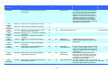
Overview
8
What is Universal RAID Utility?
Structure of Universal RAID Utility
Functional difference from Universal RAID Utility Ver1.4
Setup of Universal RAID Utility
8
9
10
12
Operation Environments
12
Hardware
Software (Windows)
Software (Linux)
Software (VMware ESX Server)
Others
12
12
13
13
13
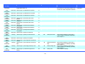
Installation and Uninstallation
15
Preparing installation (Windows)
New Installation (Windows)
Update Installation (Windows)
Add Installation (Windows)
Uninstallation (Windows)
Preparing installation (Linux)
New Installation (Linux, VMware ESX Server)
Update Installation (Linux, VMware ESX Server)
Add Installation (Linux, VMware ESX Server)
Uninstallation (Linux, VMware ESX Server)
16
17
18
19
20
21
21
22
22
22
Starting or Stopping Universal RAID Utility
raidsrv service
23
23
Starting Universal RAID Utility in Single User Mode
23
RAID Viewer
Log Viewer
raidcmd
Standard and Advanced Modes
24
25
26
27
Running Mode when startup RAID Viewer and raidcmd
Changing Running Mode
Functions of RAID Viewer
28
28
29
Structure of RAID Viewer
Tree View
29
29
Computer
RAID Controller
Battery
Disk Array
Logical Drive
Physical Device
Shortcut Menu
30
30
30
30
31
31
31
Operation View
Menu Bar
32
33
[File] menu
[Control] menu
[Tool] menu
[Help] menu
33
33
34
34
4
Status Bar
35
Functions of Log Viewer
36
Structure of Log Viewer
Log View
Menu Bar
36
37
37
[File] menu
[Help] menu
37
38
Functions of raidcmd
39
Command Line
Returned Value from raidcmd
Error Messages of raidcmd
Commands of raidcmd
Termination of raidcmd
39
39
39
39
39
Referring to Information on RAID System
40
Referring to Property of RAID Controller
Referring to Property of Battery
Referring to Property of Logical Drive
Referring to Property of Physical Device
Referring to Property of Disk Array
Checking Execution Status of Operation
Updating Information of RAID System
Referring to RAID System Operation Log
40
41
42
44
45
46
47
47
Configuration of RAID System
48
Making Hot Spare
49
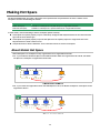
About Global Hot Spare
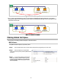
About Dedicated Hot Spare
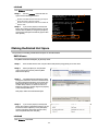
Making Global Hot Spare
Making Dedicated Hot Spare
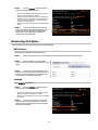
Removing Hot Spare
49
50
51
52
53
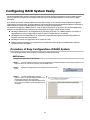
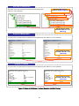
Configuring RAID System Easily
54
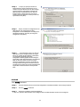
Procedure of Easy Configuration of RAID System
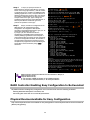
RAID Controller Enabling Easy Configuration to Be Executed
Physical Devices Available for Easy Configuration
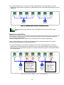
Creating Logical Drives by Easy Configuration
Making Hot Spares by Easy Configuration
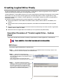
Creating Logical Drive Easily
Operation Procedure of "Create Logical Drive - Simple Mode"
Physical Devices Available for "Create Logical Drive - Simple Mode"
Creating Logical Drives by "Create Logical Drive - Simple Mode"
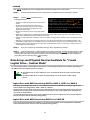
Creating Logical Drive Freely
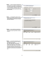
Operation Procedure of "Create Logical Drive - Custom Mode"
Disk Arrays and Physical Devices Available for "Create Logical Drive - Custom Mode"
Creating Logical Drives by "Create Logical Drive - Custom Mode"
54
56
56
57
59
61
61
63
63
64
64
67
68
Deleting Logical Drive
69
Deleting Logical Drive
69
Maintenance of RAID System
70
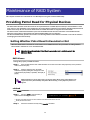
Providing Patrol Read for Physical Devices
70
Setting Whether Patrol Read Is Executed or Not
Checking Result of Executing Patrol Read
70
71
5
Setting Patrol Read Priority
71
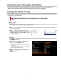
Checking Logical Drive Consistency
72
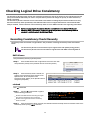
Executing Consistency Check Manually
Executing Consistency Check for arbitrary Logical Drive
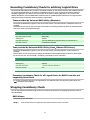
Stopping Consistency Check
Checking Result of Executing Consistency Check
Setting Consistency Check Priority
Initializing Logical Drive
Executing Initialization
Stopping Initialization
Checking Result of Executing Initialization
Setting Initialization Priority
76
76
77
77
77
Rebuilding Physical Device
79
Executing Rebuild
Stopping Rebuild
Checking Result of Executing Rebuild
Setting Rebuild Priority
79
80
80
80
Checking Location of Physical Device
82
Procedure of Checking Location of Physical Device
82
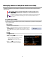
Changing Status of Physical Device Forcibly
83
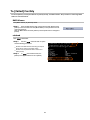
To [Online] Forcibly
To [Failed] Forcibly
83
84
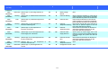
Troubleshooting RAID System
85
Failure Detection Measures
86
Status Display by RAID Viewer
Status Display by raidcmd
Logging Events to RAID Log
Buzzer in RAID Controller
Logging Events to OS Log
Sending Alert to NEC ESMPRO Manager
86
86
86
86
87
87
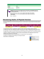
Monitoring Faults of Physical Devices
Operation
Operation
Operation
Operation
72
73
73
74
74
88
in no failures of Physical Devices
when redundancy of Logical Drive degraded or lost due to failure of Physical Device
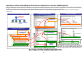
when failed Physical Device is replaced to recover RAID System
when the Logical Drive is offline due to failure of Physical Device
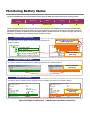
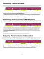
Monitoring Battery Status
Monitoring Enclosure Status
Monitoring Various Events of RAID System
Replacing Physical Device for Prevention
Changing of Settings of Universal RAID Utility
Changing TCP port number
89
90
91
92
93
94
94
94
96
96
Using Windows as Operating System
Using Linux or VMware ESX Server as Operating System
Changing Running Mode at Start of RAID Viewer
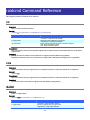
raidcmd Command Reference
96
97
97
98
cc
ccs
delld
econfig
help
hotspare
init
mkldc
98
98
98
99
99
99
100
100
6
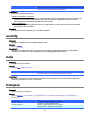
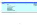
mklds
oplist
optctrl
optld
property
rebuild
rescan
runmode
sbuzzer
slotlamp
stspd
102
103
103
104
104
105
105
105
106
106
106
Notes on Use of Universal RAID Utility
108
Operation Environment
108
Use of IPv6
Use of Universal RAID Utility from Remote System
108
108
RAID Viewer, Log Viewer
108
Verification authenticode signature when startup the RAID Viewer and Log Viewer
Appendix A : Glossary
108
109
Basic Terms on RAID System
Basic Terms on Functions of RAID System
Basic Terms on Universal RAID Utility
109
110
110
Appendix B : Logs/Events
111
7
Overview
This chapter describes the overview of the Universal RAID Utility.
What is Universal RAID Utility?
The Universal RAID Utility enables RAID Systems in a computer to be managed.
The Universal RAID Utility is characterized as follows.
1. Allowing a variety of RAID Systems to be managed
Conventionally, a specific management utility must be used for each RAID System. On the other hand, only the
Universal RAID Utility can manage more than one RAID System. For the RAID Systems which the Universal
RAID Utility can manage, refer to the documentation on computers and RAID Systems.
2. Operating in either Standard or Advanced Mode
The Universal RAID Utility can operate in two running modes, which are Standard Mode and Advanced Modes.
The Standard Mode provides the Universal RAID Utility with standard management functions of RAID Systems.
The Advanced Mode provides the Universal RAID Utility with advanced management and maintenance
functions of RAID Systems.
Using the two running modes appropriately depending on users and jobs allows the usability of the Universal
RAID Utility to be improved and malfunctions to be avoided.
3. Configuring RAID Systems easily
Using the Universal RAID Utility, you can configure a RAID System easily without expert knowledge of the RAID
System.
The Universal RAID Utility provides the "simple Logical Drive create function" allowing a Logical Drive to be
created by selecting only two selection items according to the guide of the Universal RAID Utility and the "Easy
Configuration" allowing a RAID System to be configured only by defining uses of unused Physical Devices.
4. Supporting general functions required for configurations, operations and maintenances of RAID Systems
The Universal RAID Utility supports general functions for configuring a RAID System (including creating Logical
Drive and making Hot Spare), general operation functions (including log recording, Patrol Read and Consistency
Check), and general functions required for maintenance (including Rebuild and Locate functions).
5. Troubleshooting RAID Systems
The Universal RAID Utility can detect failures occurred in RAID Systems by using various functions.
The RAID Viewer, the GUI of the Universal RAID Utility, indicates the configurations and status of RAID Systems
comprehensibly with trees and icons. The raidcmd, the CLI of the Universal RAID Utility, indicates the same
information too. In addition, the Universal RAID Utility registers failures occurred in RAID Systems not only to
the dedicated log but also the OS log. Further, the Universal RAID Utility can send alerts to the NEC ESMPRO
Manager normally attached to NEC Express series systems.
8
Structure of Universal RAID Utility
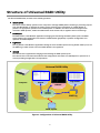
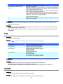
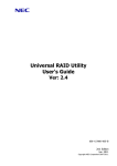
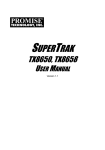
The Universal RAID Utility consists of the following modules:
raidsrv service
The raidsrv service always operates in the computer to manage RAID Systems. Receiving a processing request
from the RAID Viewer or raidcmd, the raidsrv service provides proper information on a RAID System or
performs an appropriate operation for the RAID System. In addition, the raidsrv service manages events
occurred in RAID Systems, notifies the RAID Viewer of the events and/or registers them to several logs.
RAID Viewer
The RAID Viewer is the Windows application managing and monitoring the RAID system by GUI. The RAID
Viewer displays the configuration and status of a RAID System graphically or provides configuration and
operation for a RAID System.
Log Viewer
The Log Viewer is the Windows application viewing the event of RAID system. The Log Viewer allows you to see
the RAID Log in which events occurred in RAID Systems are registered.
raidcmd
The raidcmd is the application managing and monitoring the RAID system by CLI.
The raidcmd is the command that indicates the configuration and status of a RAID System or operates on a
console providing configurations and operations.
Universal RAID Utility
Computer
RAID
Viewer
Log Viewer
raidcmd
raidsrv
service
RAID Log
RAID System
Figure 1 Configuration of Universal RAID Utility
9
The usable modules are different by the version of Universal RAID Utility or the kind of operating system. See the
following table for detail.
Operating System
Windows
Linux
VMware ESX Server
raidsrv service
RAID Viewer
Log Viewer
raidcmd
Functional difference from Universal RAID Utility
Ver1.4
Universal RAID Utility Ver2.0 executed the functional enhancement and the function change in the following from
Ver1.4.
1. Addition of hardware for management
"Promise RAID Controller" is added to the RAID Controller for management
SSD(Solid State Drive) is supported
HDD and SSD can be distinguished by the item of the device type in the property of a Physical Device.
See "Referring to Property of Physical Device".
HDD and SSD cannot exist together in the same Logical Drive. Be careful when creates a Logical Drive
or create the Hot Spare.
Physical Devices other than HDD(SSD is included) are managed
The tape device, the CD drive, and the DVD drive connected with the RAID controller can be referred to
in the tree view and property. However, the state monitoring functions of a physical device other than
HDD (SSD is included) are not supported.
2. Configuration
The condition that a logical drive can be deleted is changed
You are not able to delete a Logical Drive with boot partition until Ver 1.4.
The condition of the Logical Drive that was able to be deleted was changed in Ver 2.0. For detail, see
"Deleting Logical Drive".
3. Operation
The initialization execution condition of a logical drive is changed
You are not able to initialize a Logical Drive with boot partition until Ver1.4.
The condition of the Logical Drive that was able to be initialized was changed in Ver2.0. For detail, see
"Initializing Logical Drive".
Timing in which the Patrol Read is executed is changed
The Patrol Read was executed always continuously until Ver1.4.
The timing in which the Patrol Read is executed is changed in Ver2.0. For detail, see "Providing Patrol
Read for Physical Devices".
The way of turn off the lamp for checking location of Physical Device is changed
To turn off the lamp for checking location of Physical Device, always use the RAID Viewer or raidcmd
until Ver1.40. When the fixed time had passed since the lamp was turned on, the function to
turn off the lamp was added in Ver2.0.
4. Display of information
The tree view of the RAID viewer is changed
The Disk Array and the Battery were newly displayed as a node, and the entire tree composition was
changed. For detail, see "Tree View".
The design of the icon used by the RAID viewer is changed
10
Use the omission mark in the RAID Viewer and raidcmd. The Logical Drive is displayed as "LD" and
Physical Device is displayed as "PD".
"Queued" and "Paused" is added to the status of operation
The update function about information of RAID system is added
Supports "Rescan" of RAID Viewer and "rescan" command of raidcmd as the function which updates
the managed information in the Universal RAID Utility in Ver 2.0. Deleted the old "Rescan" function of
RAID Viewer of Ver1.4.
5. Log/Event
For detail, see "Appendix B : Logs/Events".
Change address description in the event of Physical Device
It became one parameter though the vendor and model of a Physical Device were separate
parameters.
Add Log/Event
ID : 0213 - 0217, 0321 - 0324, 0426 - 0434, 0509, 0607
Change content of Log/Event
ID : 0319, 0320, 0413, 0422, 0423, 702
6. Usability
Add help function of raidcmd
For detail, see "help".
11
Setup of Universal RAID Utility
This chapter describes installation or uninstallation of the Universal RAID Utility.
Operation Environments
The Universal RAID Utility can operate in the following environments.
Hardware
Computers
The computers can contain RAID Systems to be managed by the Universal RAID Utility.
RAID Systems to be managed by Universal RAID Utility
For RAID Systems which can be managed by the Universal RAID Utility, refer to the documentation attached
to the computer in which RAID Systems are installed and that attached to the RAID Controller including the
Universal RAID Utility.
Software (Windows)
Operating systems
The Universal RAID Utility can operate in the following operating systems.
It can operate in either 32-bit or 64-bit environment for any operating system other than Windows 2000.
Windows Server 2008
Windows Server 2003 R2 SP1 or later
Windows Server 2003 SP1 or later
Windows 2000 SP4
Windows Vista
Windows XP Professional SP2 or later
If you use "Server Core Install Option" of Windows Server 2008, you can use raidcmd for the
management of the RAID system only (You can not use RAID Viewer and Log Viewer).
Microsoft .NET Framework
To use the Universal RAID Utility, Microsoft .NET Framework Version 2.0 or higher is required.
If the operating system installed in your computer is any of those listed below, install Microsoft .NET
Framework Version 2.0:
Windows Server 2003 R2 SP1 or later
Windows Server 2003 SP1 or later
Windows 2000 SP4
Windows XP Professional SP2 or later
For the installation of Microsoft .NET Framework Version 2.0 or higher, see "Preparing installation
(Windows)".
12
Runtime component of Microsoft Visual C++ library
To use the Universal RAID Utility, the runtime component of the Microsoft Visual C++ library is required.
For the installation of the runtime component of the Microsoft Visual C++ library, see "Preparing installation
(Windows)".
Software (Linux)
Operating systems
The Universal RAID Utility can operate in the following operating systems.
It can operate in either 32-bit or 64-bit environment for any operating system.
Red Hat Enterprise Linux 4.5 or later
Red Hat Enterprise Linux 5.1 or later
MIRACLE LINUX V4.0 SP 2 or later
Asianux Server 3
Software (VMware ESX Server)
VMware ESX Server
The Universal RAID Utility can operate in the following VMware ESX Server.
VMware ESX 3.5 Update 1 or later
You must install the Universal RAID Utility in the ESX Server. Don't install in the virtual machine.
Others
System Requirements
Resource
Available Hard Disk Space
RAM
Windows
Linux/VMware ESX Server
50MB or more
←
(not include Microsoft .NET Framework (not include the required packages as
Ver2.0 、 the runtime of Microsoft Visual standard C++ library...etc)
C++ 2005 SP1 library)
512MB or more
←
TCP ports used by Universal RAID Utility
The Universal RAID Utility uses the following two TCP ports.
TCP ports used by Universal RAID Utility
52805 and 52806
For the change of TCP ports number using Universal RAID Utility, see "Changing TCP port number".
13
Safe Mode and Single User Mode
The Universal RAID Utility uses the network function. Accordingly, the Universal RAID Utility is unavailable in
any of the following safe modes in which the network function cannot operate.
Safe Mode
Safe Mode with Command Prompt
Safe Mode with Networking
Also, cannot be used in the single user mode of Linux and VMware ESX Server. For how to use the Universal
RAID Utility in the single user mode, see "Starting Universal RAID Utility in Single User Mode".
14
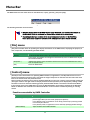
Installation and Uninstallation
This section describes the procedure of installation and uninstallation of Universal RAID Utility.
The working procedure is different by the kind of installation or uninstallation.
kind
Description
New Installation
Install Universal RAID Utility newly, when there is not Universal RAID Utility in the computer.
Procedure (Windows)
1.
Preparing installation (Windows)
2.
New Installation (Windows)
Procedure (Linux)
1.
Preparing installation (Linux)
2.
New Installation (Linux, VMware ESX Server)
Procedure (VMware ESX Server)
1.
Update Installation
New Installation (Linux, VMware ESX Server)
Install the new version of Universal RAID Utility, when there is the old version of Universal
RAID Utility in the computer
Procedure (Windows)
1.
Update Installation (Windows)
Procedure (Linux、VMware ESX Server)
1.
Add Installation
Update Installation (Linux, VMware ESX Server)
Install or uninstall the program to control the RAID Controller after added or deleted the RAID
Controller.
Procedure (Windows)
1.
Add Installation (Windows)
Procedure (Linux、VMware ESX Server)
1.
Uninstallation
Add Installation (Linux, VMware ESX Server)
Uninstall Universal RAID Utility from the computer.
Procedure (Windows)
1.
Uninstallation (Windows)
Procedure (Linux、VMware ESX Server)
1.
Uninstallation (Linux, VMware ESX Server)
Use the setup program of Universal RAID Utility for the installation and the uninstallation.
The setup program is contained in the installation image of the Universal RAID Utility. Before the Universal RAID Utility
can be installed or uninstalled, you must prepare the installation image.
The setup program of Windows is " setup.exe". The setup program of Linux and VMware ESX Server is "setup.sh".
The installation image of the Universal RAID Utility for Windows and Linux is contained in
an accessory of the computer or RAID Controller.
About Universal RAID Utility for VMware ESX Server, please contact our support.
15
A user having the administrator authority should install or uninstall the Universal RAID
Utility in the computer. Only users having the administrator authority can execute the
setup program.
If you use "Server Core Install Option" of Windows Server 2008, there is not [Start] menu.
You must run setup.exe on the [Administrator : Command Prompt].
If you use VMware ESX Server, press Alt key and F1 key at boot screen of VMware ESX
Server to switch to service console. Log in to VMware ESX Server with administrator
authority to install or uninstall Universal RAID Utility.
You must close RAID Viewer and Log Viewer, raidcmd, Event Viewer when will uninstall
Universal RAID Utility.
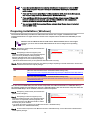
Preparing installation (Windows)
The Universal RAID Utility uses Microsoft .NET Framework Version 2.0 or higher. Install Microsoft .NET
Framework Version 2.0 or higher if it does not exist in the computer where the Universal RAID Utility is to be
installed.
Windows Vista and Windows Server 2008 include .NET Framework Version 2.0 or higher.
Therefore, you don't need to install .NET Framework in case of using them as operating
system.
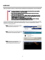
Step 1 Click [Start] - [Control Panel]. Then double-click
[Add or Remove Program].
Step 2 Click [Change or Remove Program] to list
[Currently installed programs]. If the following programs
exist in the list of [Currently installed programs],
Microsoft .NET Framework may not be installed. If the
following packages do not exist, install the package(s).
- [Microsoft .NET Framework 2.0] (for x64, [Microsoft .NET Framework 2.0 (x64)])
Step 3 Microsoft .NET Framework Version 2.0 uses different packages depending on the CPU architecture. See the table
below to download and install the required packages.
CPU architecture
x86
Required components and their vendors
[Microsoft .NET Framework Version 2.0 Redistributable Package (x86)]
http://www.microsoft.com/downloads/details.aspx?FamilyID=0856EACB-4362-4B0D-8EDD-A
AB15C5E04F5&displaylang=en
x64
[Microsoft .NET Framework Version 2.0 Redistributable Package (x64)]
http://www.microsoft.com/downloads/details.aspx?familyid=92e0e1ce-8693-4480-84fa-7d85
eef59016&displaylang=en
Also, The Universal RAID Utility uses the runtime component of the Microsoft Visual C++ 2005 SP1 library. If
the runtime component of the Microsoft Visual C++ 2005 SP1 library does not exist in the computer where the
Universal RAID Utility is to be installed, install the runtime component.
Step 1 Click [Start] - [Control Panel]. Then double-click
[Add or Remove Program].
Step 2 Click [Change or Remove Programs] to list
[Currently installed programs]. If the following program
exists in the list of [Currently installed programs], the
runtime component of the Microsoft Visual C++ 2005
SP1 library may not be installed.
If not, install the runtime component of the Microsoft Visual C++ 2005 SP1 library.
- [Microsoft Visual C++ 2005 Redistributable]
Step 3 For the runtime component of the Microsoft Visual C++ 2005 SP1 library, see the table below to download and
install required packages.
16
CPU architecture
x86/x64
Required component and its vendor
[Microsoft Visual C++ 2005 SP1 Redistributable Package (x86)]
http://www.microsoft.com/downloads/details.aspx?FamilyID=200b2fd9-ae1a-4a14-984d-389
c36f85647&displaylang=en
Use the x86 package whatever the CPU architecture may be.
There is not the description about Windows Server 2008 in "System Requirements" - "Supported
Operating Systems." But if you use Windows Server 2008 as the operating system, you need to
install this package.
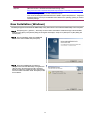
New Installation (Windows)
The Setup Program install Universal RAID Utility newly, when there is not Universal RAID Utility in the computer.
Step 1 Click [Start], [Run…], [Browse...]. Click setup.exe in the folder contained the installation image of Universal RAID
Utility and click [Open] in the [Browse] dialog box. Recognize that displays "setup.exe" in [Name] box on [Run] dialog box
and click [OK].
Step 2 The new installation starts the InstallShield
Wizard of the Universal RAID Utility. Click [Next].
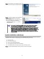
Step 3 The Universal RAID Utility is installed in
\Program Files\Universal RAID Utility (or Program Files
(x86) for x64) in the drive where the OS is started by
default. To change the installation folder, click [Change]
and enter another installation folder. Click [Next] to start
the installation.
17
Step 4 At the completion of the installation, the wizard
appears as shown in the figure to the right. Click [Finish].
Step 5 If installation completes, "Universal RAID Utility"
is registered to the program list in the [Change or
Remove Programs].
Also, 1 or several programs to control RAID controller in
your system are registered to the program list.
- LSI SAS Storage SNMP Agent X
- WebPAMPRO Agent
(X
is version)
Don't uninstall " LSI SAS Storage SNMP Agent X " (X is version) in the list of [Add or
Remove Program]. If you uninstall it, Universal RAID Utility can't use normally.
Please check the setting of [When maximum log size is reached] in the [Properties] of
[System] event log. In case of [When maximum log size is reached] is not [Overwrite
events as needed], when log size reaches maximum size, Universal RAID Utility can not
register the detected RAID event to the Windows event log and alert it to the NEC
ESMPRO Manager. Please set [When maximum log size is reached] to the [Overwrite
events as needed].
Update Installation (Windows)
The Setup Program install the new version of Universal RAID Utility, when there is the old version of Universal
RAID Utility in the computer. The Setup Program use the following setting continuously.
Installation folder
The contents of RAID log
TCP port using Universal RAID Utility
The running mode of RAID Viewer and raidcmd
The scheduled task of consistency check in task of operating system
Step 1 See "New Installation (Windows)" about the procedure of start the setup program.
18
Step 2 The update installation starts the InstallShield
Wizard of the Universal RAID Utility. Click [Next].
Step 3 At the completion of the installation, the wizard
appears as shown in the figure to the right. Click [Finish].
You can check the result of installation by the same way
with "New Installation (Windows)".
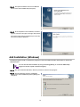
Add Installation (Windows)
The Setup Program install or uninstall the program to control the RAID Controller after added or deleted the
RAID Controller.
You can start the add installation by using the clicking [Modify] on "Universal RAID Utility"
program in the list of [Add or Remove Program].
Step 1 See "New Installation (Windows)" about the procedure of start the setup program.
Step 2 The add installation starts the InstallShield
Wizard of the Universal RAID Utility. Select [Modify] and
click [Next].
19
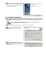
Step 3 At the completion of the installation, the wizard
appears as shown in the figure to the right. Click [Finish].
You can check the result of installation by the same way
with "New Installation (Windows)".
Uninstallation (Windows)
The Setup Program uninstall Universal RAID Utility, when there is the same version of Universal RAID Utility in
the computer.
You can start the uninstallation by using the clicking [Delete] on "Universal RAID Utility"
program in the list of [Add or Remove Program].
Step 1 See "New Installation (Windows)" about the procedure of start the setup program.
Step 2 The uninstallation starts the InstallShield
Wizard of the Universal RAID Utility. Select [Remove]
and click [Next].
Step 3 The InstallShield Wizard of the Universal RAID
Utility is started. Click [Yes] on the dialog box shown to
the right to start the uninstallation. Click [No] to abort
the setup program.
20
Step 4 At the completion of the uninstallation, the
wizard appears as shown in the figure to the right. Click
[Finish].
If the uninstallation completes, "Universal RAID Utility"
is deleted from the list of [Add or Remove Program].
Also, 1 or several programs to control RAID controller in
your system are deleted too.
Preparing installation (Linux)
You must prepare the following package for using the Universal RAID Utility. If it does not exist in the computer
where the Universal RAID Utility is to be installed.
standard C++ library : libstdc++
GCC 3.3.4 Compatibility standard C++ library : compat-libstdc++-33
GCC library : libgcc
cron : vixie-cron
You can recognize the existence and install these packages by the following procedure (This procedure is
example using GCC 3.3.4 Compatibility standard C++ library).
Step 1 You can check by rpm command which does
GCC 3.3.4 Compatibility standard C++ library exist in the
> rpm -q compat-libstdc++-33
1
compat-libstdc++-33-3.2.3-*
computer or not. If it has existed in your computer, rpm
>
command displays the right way (the part of "*" is
different by operating system). In this case, refer to "New Installation (Linux, VMware ESX Server)". If it has not existed in
your computer, rpm command displays the right way. In this case, install it to your computer.
Step 2 Log in to the computer with administrator
2
authority to install Universal RAID Utility.
Insert the install disk of operating system included the
"GCC 3.3.4 Comparability standard C++ library" to
CD-ROM/DVD-ROM drive of your computer.
> rpm -q compat-libstdc++-33
package compat-libstdc++-33 is not installed
> rpm -ivh compat-libstdc++-33-*.i386.rpm
Preparing...
##############################
[100%]
1:compat-libstdc++-33 ##############################
[100%]
> rpm -q compat-libstdc++-33
compat-libstdc++-33-3.2.3-*
>
Step 3 Move current directory to the directory existed
GCC 3.3.4 Compatibility standard C++ library, install it
by rpm command (the part of "*" is different by
operating system).
3
Step 4 You can see the result of installation by rpm command. If the installation finishes, rpm command displays the
below
compat-libstdc++-33-3.2.3-*
(the part of "*" is different by operating system)
If the installation fails, rpm command does not display this package name.
New Installation (Linux, VMware ESX Server)
Use setup.sh in the install image for the installation of Universal RAID Utility newly.
21
You must install the Universal RAID Utility in the ESX Server. Don't install in the virtual
machine.
Step 1 Execute setup.sh in the installation image.
Change the current directory to the directory in which
the installation image is stored and type as follows:
sh setup.sh --install
> cd directory name involved install image
> sh setup.sh --install
>
> rpm -q UniversalRaidUtility
UniversalRaidUtility-1.xx-y
>
> rpm -q storelib
storelib-2.aa-0
>
> rpm -q WebPAMPRO_Agent
WebPAMPRO_Agent-3.aa.bbbb-cc
>
1
Step 2 At the end of setup.sh, the installation is
completed. Check the result of the installation by using
the rpm command. When the installation is completed
properly, the following packages is installed:
- UniversalRAIDUtility-1.xx-y (xx is minor version, y is
revision number)
Also, 1 or several packages to control RAID controller
are installed :
- storelib-2.aa-0. (aa is minor version)
- WebPAMPRO_Agent-3.aa.bbbb-cc (aa.bbbb-cc is version)
If the installation fails, these packages do not exist in the computer.
2
Update Installation (Linux, VMware ESX Server)
The Setup Program execute the Update Installation when there is the old version of Universal RAID Utility in the
computer. The Setup Program use the following setting continuously.
The contents of RAID log
TCP port using Universal RAID Utility
The running mode of raidcmd
The scheduled task of consistency check in crontab of operating system
See "New Installation (Linux, VMware ESX Server)" about the procedure of Update Installation.
Add Installation (Linux, VMware ESX Server)
The Setup Program execute the Add Installation when there is the same version of Universal RAID Utility in the
computer. In add installation, install or uninstall the program to control the RAID Controller after added or
deleted the RAID Controller.
See "New Installation (Linux, VMware ESX Server)" about the procedure of Update Installation.
Uninstallation (Linux, VMware ESX Server)
Use setup.sh in the install image for the uninstallation of Universal RAID Utility.
Step 1 Execute setup.sh in the installation image.
Change the current directory to the directory in which
the installation image is stored and type as follows:
sh setup.sh --uninstall
> cd directory name involved install image
> sh setup.sh --uninstall
>
> rpm -q UniversalRaidUtility
error: package UniversalRaidUtility is not installed
>
> rpm -q storelib
error: package storelib is not installed
>
> rpm -q WebPAMPRO_Agent
error: package WebPAMPRO_Agent is not installed
>
1
Step 2 At the end of setup.sh, the uninstallation is
completed. Check the result of the uninstallation by
using the rpm command. When the uninstallation is
completed properly, the following package is
uninstalled:
- UniversalRaidUtility-1.xx-y (xx is minor version, y is
revision number)
Also, 1 or several packages to control RAID controller are uninstalled too.
22
2
Starting or Stopping Universal RAID
Utility
This chapter describes the procedure of starting or stopping each module in the Universal RAID Utility.
raidsrv service
The raidsrv service is started automatically when your computer is booted and stopped automatically when your
computer is shut down.
Without operation of the raidsrv service, the Universal RAID Utility cannot operate normally. Neither make the raidsrv
service be not started nor stop the raidsrv service.
In case of the operating system is Linux or VMware ESX Server, if the raidsrv service
terminates abnormally due to occurrence of an error or a process of the raidsrv service is
terminated forcibly, the lock file for avoiding double starts is left. If the state remains, the
raidsrv service may not be started.
If this occurs, delete the following file before restarting the raidsrv service:
/var/lock/subsys/raidsrv
Starting Universal RAID Utility in Single User Mode
The Universal RAID Utility uses network functions. Accordingly, the Universal RAID Utility cannot be used in the
single user mode of Linux and VMware ESX Server without network functions. To use the Universal RAID Utility
in the single user mode, first enable the network functions in the following procedure and start the raidsrv
service.
Step 1 Start the network service.
Step 2 Start the raidsrv service.
Step 3 Check that the raidsrv service is started normally.
If a process ID appears, the raidsrv service is started
normally.
23
> /etc/init.d/network start
>
> /etc/init.d/raidsrv start
>
> /etc/init.d/raidsrv status
raidsrv (pid 3738 3718) is running...
>
1
2
3
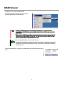
RAID Viewer
Use [Start] menu to open the RAID Viewer.
Click [Start], and point menu in order to [Programs],
[Universal RAID Utility] and [RAID Viewer].
To use the RAID Viewer, you should log on to the computer as a user having the
administrator authority. Only users having the administrator authority can execute the
RAID Viewer.
When start the RAID Viewer on the computer not connected to internet, may wait a few
minutes until startup the RAID Viewer. See "Verification authenticode signature when
startup the RAID Viewer and Log Viewer" for detail.
Only a single RAID Viewer can be started at a time.
The RAID Viewer cannot be started if the raidsrv service does not operate. An error may
occur if the RAID Viewer is started just after the start of the OS. It is because the raidsrv
service has not been started completely. In this case, wait for a while before restarting
the RAID Viewer.
To close the RAID Viewer, select [File] on the Menu Bar of the RAID Viewer and click
[Exit].
24
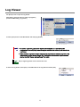
Log Viewer
Use [Start] menu to open the Log Viewer.
Click [Start], and point menu in order to [Programs],
[Universal RAID Utility], [Log Viewer].
Or select [Tool] menu of the RAID Viewer and click [Log Viewer].
To use the Log Viewer, you should log on to the computer as a user having the
administrator authority. Only users having the administrator authority can execute the
Log Viewer.
When start the Log Viewer on the computer not connected to internet, may wait a few
minutes until startup the Log Viewer. See "Verification authenticode signature when
startup the RAID Viewer and Log Viewer" for detail.
Only a single Log Viewer can be started at a time.
To close the Log Viewer, select [File] on the Menu Bar of the Log Viewer and click [Exit].
25
raidcmd
raidcmd is command on console as "Command Prompt" in Windows and console(terminal) in Linux and VMware ESX
Server. The raidcmd is executed on a console. Use the raidcmd by the methods described in "Functions of raidcmd".
A user having the administrator authority should run the raidcmd. Only users having the
administrator authority can execute the raidcmd.
In case of the operating system is Windows 2000, you must to restart the Command
Prompt after New/Update installation.
In case of the operating system is Linux or VMware ESX Server, the raidcmd can't start by
existing the lock file after aborted it. If you start the raidcmd when the lock file exists, the
raidcmd displays the following message.
raidcmd:<RU4009> The raidcmd command is already running.
Delete the lock file (/var/lock/subsys/raidcmd), if the raidcmd displays this message
when some processes of the raidcmd don't execute at same time,
In case of the operating system is Windows Server 2008 or Windows Vista, you must use "[Administrator: Command
Prompt]" for running raidcmd. If you use normal Command Prompt, you can not see the message of raidcmd because
of raidcmd runs in the another "[Administrator: Command Prompt]" . You can use "[Administrator: Command
Prompt]" by the following procedure.
Step 1 Click [Start] menu, and point menu in order to
[Programs], [Accessories], [Command Prompt], click
[Run as administrator] on shortcut menu.
Step 2 The operating system may display [User Account
Control] dialog box after clicked [Run as Administrator].
If you want to run the raidcmd, click [Continue].
Step 3 [Administrator: Command Prompt] will start
soon. You should check the window title is
"[ Administrator: Command Prompt]". You can use
raidcmd on [Administrator: Command Prompt].
3
26
Standard and Advanced Modes
The RAID Viewer and raidcmd can operate in two running modes, which are Standard Mode and Advanced Modes.
The Standard Mode provides the RAID Viewer and raidcmd with standard management functions for RAID Systems.
The Advanced Mode provides the RAID Viewer and raidcmd with advanced management and maintenance functions
for RAID Systems.
Using the two running modes appropriately depending on users and jobs allows the usability of the RAID Viewer to be
improved and malfunctions to be avoided.
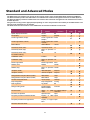
The table below lists the functions of the RAID Viewer and raidcmd available in each mode.
Function
RAID Viewer
raidcmd
Standard
Advanced
function
command
mode
mode
Update display information
Rescan
NA
See property
Property
property
Create Logical Drive (simple)
Create Logical Drive mklds
(Simple)
Create Logical Drive (custom)
Create Logical Drive mkldc
(Custom)
Silence Buzzer
Silence Buzzer
sbuzzer
Consistency Check (start)
Consistency Check
cc
Consistency Check (stop)
[Stop] on Operation cc
View
Consistency Check (start)
for schedule running
NA
ccs
Initialization (start)
Initialize
init
Initialization (stop)
[Stop] on Operation init
View
Delete Logical Drive
Delete Logical Drive delld
Rebuild (start)
Rebuild
Rebuild (stop)
[Stop] on Operation rebuild
View
Hot Spare (make)
Make Hot Spare
hotspare
Hot Spare (remove)
Remove Hot Spare
hotspare
Change Status of Physical Device (Online)
Make Online
stspd
Change Status of Physical Device (Failed)
Make Offline
stspd
Location of Physical Device
Locate (Lamp)
slotlamp
rebuild
Easy Configuration
Easy Configuration
econfig
Start Log Viewer
Log Viewer
NA
Change running mode
Standard Mode
Advanced Mode
runmode
See the version
About...
menu
See status of operation
Operation View
Set option parameters of RAID Controller
Property of
Controller
Set option parameters of Logical Drive
Property of Logical optld
Drive
Functions other than above
27
in
[Help] run raidcmd without
command
oplist
RAID optctrl
Running Mode when startup RAID Viewer and raidcmd
RAID Viewer
RAID Viewer always starts with Standard Mode. You can change the running mode when RAID Viewer starts.
See "Changing Running Mode at Start of RAID Viewer".
raidcmd
raidcmd starts with Standard Mode at first after installing Universal RAID Utility. If you want to change the
running mode, you must to use "rescan" command (The running mode doesn't change the mode when
restart the computer).
Changing Running Mode
The procedure of changing the running mode is below.
RAID Viewer
Use [Advanced] or [Standard] in [Tool] menu.
See "[Tool] menu" for detail.
raidcmd
Use "runmode" command.
Step 1
If you want to change from Standard
Mode to Advanced Mode, run "runmode" command
with -md=a parameter.
1
> raidcmd runmode -md=a
Changed running mode to "Advanced Mode".
>
>
> raidcmd runmode -md=s
Changed running mode to "Standard Mode".
>
2
Step 2
If you want to change from Advanced
Mode to Standard Mode, run "runmode" command
with -md=s parameter.
28
Functions of RAID Viewer
This chapter describes the functions of the RAID Viewer.
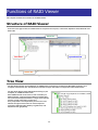
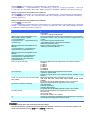
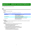
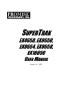
Structure of RAID Viewer
As shown in the figure below, the RAID Viewer is composed of four parts, or Tree View, Operation View, Menu Bar and
Status Bar.
Menu Bar
Operation View
Tree View
Status Bar
Figure 2 Structure of RAID Viewer
Tree View
The Tree View indicates the configuration of RAID Systems managed by the Universal RAID Utility existing in your
computer hierarchically. The Tree View also indicates the types and status of components with relevant icons.
The Tree View displays each RAID System existing in your
computer as a RAID Controller node.
Each RAID Controller node has the node of a battery on
RAID Controller, created all Logical Drives and Disk Array
and connected all Physical Devices. A single node includes
at least a single component of each type.
Every component is accompanied by an icon. The icons
indicate the type and the status of each component
(computer, RAID Controller, Battery, Logical Drive, and
Physical Device) graphically.
29
Computer
The first level node shows the computer in which the Universal RAID Utility operates.
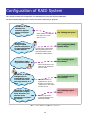
The computer icon indicates the status of the RAID Systems existing in the computer totally.
Icon
Meaning
Description
Computer - Normal
All RAID Systems in the computer operate normally. Problems which RAID
Controllers define as failures do not occur.
Computer - Warning
One or more RAID Systems of the following status exist in the computer:
"Containing one or more failed components but being operable"
Computer - Fatal
One or more RAID Systems of the following status exist in the computer:
"Containing one or more failed components and being inoperable"
RAID Controller
Each RAID System on the computer is the RAID Controller node. A RAID Controller node equals a RAID
Controller, and shows the number, ID and model of the RAID Controller.
A RAID Controller icon indicates the status of the RAID system on the RAID Controller totally.
Icon
Meaning
Description
RAID Controller - Normal
The all of components(battery, Logical Drive, Physical Device) operates
normally on the RAID Controller. Problems which the RAID Controller
detects as failures do not occur.
RAID Controller - Warning
One or more components of the following status exist on the RAID
Controller :
"Containing one or more failed components but being operable"
RAID Controller - Fatal
One or more components of the following status exist in the RAID
Controller :
"Containing one or more failed components and being inoperable"
Battery
If the RAID Controller has the battery, the RAID Controller node has a Battery node. A Battery node and icon
shows the status of battery.
Icon
Meaning
Description
Battery - Normal
The battery operates normally.
Battery - Warning
The RAID controller detects any problem of the battery.
Disk Array
If there are some Logical Drive in the RAID Controller, the RAID Controller node has the Disk Array nodes
included the Logical Drives. The Disk Array node equals a Disk Array, and shows the number and ID of the Disk
Array. Also, the created some Logical Drives, consisted of all Physical Devices and created some Dedicated Hot
Spares exist in the Disk Array node. A Disk Array icon indicates the status of these totally.
Icon
Meaning
Description
Disk Array - Normal
The created all Logical Drives, consisted of all Physical Devices and created
all Dedicated Hot Spares operates normally. Problems which the RAID
Controller detects as failures do not occur.
Disk Array - Warning
These are some components which the status is Warning.
30
Disk Array - Fatal
These are some components which the status is Fatal or Warning.
Logical Drive
The Logical Drive node exists in the Disk Array node. A Logical Drive node equals a Logical Drive, and shows the
number, ID, status and RAID Level of the Logical Drive. A Logical Drive icon indicates the status of the Logical
Drive.
Icon
Meaning
Description
Logical Drive - Normal
The Logical Drive operates normally.
Logical Drive - Warning
Because the Logical Drive contains one or more Physical Devices with
[Status] being [Failed], the redundancy of the Logical Drive is lost or
degraded.
Logical Drive - Fatal
Because the Logical Drive contains one or more Physical Devices with
[Status] being [Failed], the Logical Drive is offline and accessing to the
Logical Drive is disabled.
A Logical Drive is created by two or more Disk Arrays according to the kind of the RAID
Controller. In this case, there are the nodes of a Logical Drive exist in two of more the nodes
of Disk Arrays.
Physical Device
The Physical Device node exists in either the Disk Array node or the RAID Controller node. The Physical Device
which has created the Logical Drive and created Dedicated Hot Spare exists in the Disk Array node. The other
Physical Device exists in RAID Controller node. The Physical Device node equals a Physical Device, and shows
the number, ID, status and device type of the Physical Device.
A Physical Device icon indicates the device type and the status of the Physical Device.
Icon
Meaning
Description
Physical Device - Ready
The Physical Device is not used to create a Logical Drive yet.
Physical Device - Online
The Physical Device is already used to create a Logical Drive.
Problems which the RAID Controller detects as failures do not occur.
Physical Device - Hot Spare
The Physical Device is registered as a Hot Spare.
Physical Device - Rebuilding
The Physical Device which is rebuilding now.
Physical Device - Warning
Physical Device - Fatal
Tape Drive
CD Drive/DVD Drive
The Physical Device which detects one or more S.M.A.R.T. errors.
The Physical Device which is detected a failure by RAID Controller.
The Physical Device which device type is [Tape Drive].
The Physical Device which device type is [CD/DVD].
The nodes of Dedicated Hot Spare created to two or more Disk Arrays existed in each node
of Disk Array.
Shortcut Menu
Right-clicking the node of RAID Controller, Disk Array, Logical Drive, Physical Device and Battery allows the
shortcut menu to appear. On the shortcut menu, you can display the property and execute the something
operation. See "Menu Bar" for detail of each function.
31
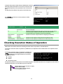
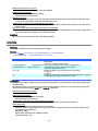
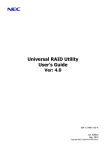
Operation View
The Operation View indicates the status and results of operations executed in the computer after the RAID Viewer is
started.
Figure 3 Operation View
The following operations may appear on the Operation View. For each operation, the target component and the status
of the operation appear.
Initialize
Rebuild
Consistency Check
Operations being executed while the RAID Viewer is started and those started after the RAID Viewer is started are
listed.
You can see the status and result of operations by the value of [Status].
Status
Description
Running (N %)
The operation is be running (N is progress).
Completed
The operation completed.
Failed
The operation failed.
Stopped
The operation stopped (by [Stop]).
Paused (N %)
The operation is paused (N is progress).
Queued
The operation is queued.
Stop Processing
The operation is processing [Stop].
Terminated operations continue to appear until the RAID Viewer is closed. However, the terminated operations will not
appear at the next start of the RAID Viewer.
To delete an operation terminated while the RAID Viewer
is started, click the operation to be deleted and [Delete].
An operation being executed can be stopped on the way.
To do this, click the operation to be stopped and [Stop].
Operations allowed to be stopped vary depending on running modes. See "Standard and
Advanced Modes" for details.
32
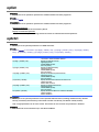
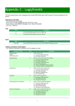
Menu Bar
The RAID Viewer has four menu items on the Menu Bar, or [File], [Control], [Tool] and [Help].
Figure 4 Menu of RAID Viewer
The following describes the menu items.
With the running mode of the RAID Viewer being "Standard", the functions unavailable in
the Standard Mode do not appear on the pull-down menus of the menu items.
Depending on the type or status of the target component selected on the Tree View,
some menu items cannot be executed. If so, clicking such a menu item is disabled.
[File] menu
[File] menu includes items for updating the display information on the RAID Viewer, displaying the property of
each component, and terminating the RAID Viewer.
Menu item
Description
[Rescan]
The Universal RAID Utility acquires the configuration and state information from all of RAID
system again, and updates the management information by them. The RAID Viewer displays
the newest information.
[Properties...]
Indicates the property of the component selected on the Tree View (RAID Controller, Logical
Drive or Physical Device).
[Exit]
Closes the RAID Viewer.
[Control] menu
[Control] menu includes items for operating RAID Controllers, Logical Drives, and Physical Devices. To use a
function subordinate to [Control] menu, first click the target component on the Tree View and select the menu
item to be executed from the pull-down menu.
Some functions of [Control] menu may be disabled depending on the type or status of the selected component.
(The figure shown to the right shows a sample pull-down menu of [Control] menu displayed by clicking a RAID
Controller on the Tree View and selecting [Control] while the RAID Viewer is executed in the Advanced Mode.)
If the running mode of the RAID Viewer is set to the Standard Mode, the functions restricted in the Standard
Mode are disabled. See "Standard and Advanced Modes" for the functions available depending on running
modes.
Functions executable by RAID Controller
Menu item
Description
[Create Logical Drive]
Creates a Logical Drive in the selected RAID Controller.
[Create Logical Drive] has two modes, [Simple] and [Custom].
In the [Simple] mode, a Logical Drive can be simply created only by selecting a RAID
Level and Physical Devices.
In the [Custom] mode, a Logical Drive can be created by specifying detailed settings.
[Silence Buzzer]
Stops the Buzzer in the RAID Controller.
33
Functions executable for Logical Drive
Menu item
Description
[Consistency Check]
Executes Consistency Check for the selected Logical Drive.
[Initialize]
Initializes the selected Logical Drive.
[Initialize] has two modes, [Full] and [Quick].
In the [Full] mode, initializes the entire area of a Logical Drive.
In the [Quick] mode, initializes only several leading blocks including the information on
managing a Logical Drive.
[Delete Logical Drive]
Deletes the selected Logical Drive.
Functions executable for Physical Device
Menu item
Description
[Rebuild]
Rebuilds the selected Physical Device.
[Hot Spare]
Makes a Hot Spare with the selected Physical Device or removes a Hot Spare.
[Make Global Hot Spare] makes Physical Devices be Global Hot Spares available as
Hot Spares of all Logical Drives in the relevant RAID System.
[Make Dedicated Hot Spare] makes Physical Devices be Dedicated Hot Spares
available as Hot Spares of specific Logical Drives.
[Remove Hot Spare] removes Physical Devices from Hot Spares.
[Make Online]
Sets the status of the selected Physical Device to online.
[Make Offline]
Sets the status of the selected Physical Device to offline.
[Locate(Lamp)]
Goes on (or blinks) the lamp on the slot where the selected Logical Drive is installed.
[ON] goes on the lamp.
[OFF] goes off the lamp.
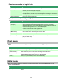
[Tool] menu
[Tool] menu includes tools used to manage RAID Systems and items for changing the operation of the RAID
Viewer.
Menu item
Description
[Easy Configuration...]
Executes Easy Configuration allowing a RAID System to be configured easily.
[Log Viewer]
Starts the Log Viewer.
[Advanced Mode] or
[Standard Mode]
Alters the running mode. The item varies depending on the running mode.
[Advanced Mode] sets the running mode to the Advanced Mode.
[Standard Mode] sets the running mode to the Standard Mode.
[Option...]
Allows you to provide settings for the Universal RAID Utility.
[Help] menu
[Help] menu includes the item of indicating the version and revision of the Universal RAID Utility and the
version of the RAID Viewer.
Menu item
[About...]
Description
Indicates the version and revision of the Universal RAID Utility and the version of the RAID
Viewer.
34
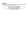
Status Bar
The Status Bar indicates the current running mode of the RAID Viewer.
Figure 5 Status Bar of RAID Viewer
35
Functions of Log Viewer
This chapter describes the functions of the Log Viewer.
Structure of Log Viewer
As shown in the figure below, the Log Viewer is composed of three parts, or Log View, Menu Bar and Status Bar.
Menu Bar
Log View
Status Bar
Figure 6 Structure of Log Viewer
The Status Bar is used only for changing the size of the Log Viewer window.
36
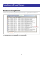
Log View
The Log View indicates RAID System operation logs logged by the raidsrv service.
You can view the following information on the Log View.
Item
Type
Description
Logs are classified into three types as follows:
Fatal: A log of the type is registered when a fatal error occurs.
Warning: A log of the type is registered when a problem occurs which is not fatal but requires your
attention.
Information: A log of the type is registered at occurrence of an event such as execution of an
operation without any problem.
Date
Indicates the date on which the event occurred.
Time
Indicates the time at which the event occurred in the 24-hour format.
Event ID
Indicates the event ID of the log.
Description
Indicates the contents of the log.
Double-clicking an arbitrary log allows the detailed
information on the log to be displayed.
Menu Bar
The Log Viewer has two menu items, or [File] and [Help] on the Menu Bar.
Figure 7 Menu of Log Viewer
The following describes each menu item.
[File] menu
[File] menu includes items for updating the display information on the Log Viewer and terminating the Log
Viewer.
37
Menu item
Description
[Refresh]
Reads the contents in the RAID Log and updates the Log View to the latest.
[Properties...]
Opens the [Event Properties] dialog box and displays the detailed information on the log
selected by the Log Viewer.
[Exit]
Closes the Log Viewer.
[Help] menu
[Help] menu includes the item of indicating the version of the Log Viewer.
Menu item
[About...]
Description
Indicates the version of the Log Viewer.
38
Functions of raidcmd
This chapter describes the functions of the raidcmd.
Command Line
To use the raidcmd, specify a command and one or more
parameters for the command if necessary.
> raidcmd command <parameters of command>
To use the raidcmd, you should log in to the computer as a user having the administrator
authority. Only users having the administrator authority can execute the raidcmd.
Executing the raidcmd without any command and its parameters indicates the version of
the raidcmd.
Returned Value from raidcmd
The returned value of the raidcmd is the result of executing the command.
Returned value
Execution result
0
Normal termination of command
1
Abnormal termination of command
Error Messages of raidcmd
When a command of the raidcmd terminates abnormally,
the relevant error message appears in the following
format:
> raidcmd (command) (parameters of command)
raidcmd : error message
>
Commands of raidcmd
See "raidcmd Command Reference" for commands of the raidcmd.
Use help command, displays the help of raidcmd.
Termination of raidcmd
In case of the operating system is Windows, raidcmd is the batch file in system folder (the batch file in system folder
call raidcmd binary in the installed folder of Universal RAID Utility). Therefore, if you terminates raidcmd by CTRL + C
key, the operating system displays the message as "Terminate batch job (Y/N)?". When displays this message,
raidcmd binary is terminated already.
39
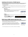
Referring to Information on RAID System
This chapter describes how to see the configurations and status of RAID Systems and the RAID System operation log.
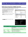
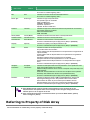
Referring to Property of RAID Controller
For the information on a RAID Controller, see the property of the RAID Controller.
To display the property of RAID Controller by RAID Viewer,
click the RAID Controller whose information is to be seen
on the Tree View and click [Properties] on the pull-down
menu of menu item [File].
The [RAID Controller Properties] dialog box has the
[General] and [Option] tabs.
The [General] tab indicates the property of the RAID
Controller.
The [Option] tab allows you to see the settings of the RAID
Controller.
You can change the settings in the Advanced Mode.
Use "property" command to see the property of a RAID
Controller by raidcmd.
Item
RAID Viewer
> raidcmd property -tg=rc -c=1
RAID Controller #1
ID
: 0
Vendor
: LSI Corporation
Model
: MegaRAID SAS PCI Express(TM)
ROMB
Firmware Version
: 1.12.02-0342
Cache Size
: 128MB
Battery Status
: Normal
Rebuild Priority
: High
Consistency Check Priority : Low
Patrol Read
: Enable
Patrol Read Priority
: Low
Buzzer Setting
: Enable
>
Item
raidcmd
Description
Number
RAID Controller #X
Indicates the management number (logical address) of the RAID Controller in
the Universal RAID Utility.
The Universal RAID Utility assigns a number beginning with 1 for each RAID
Controller.
ID
ID
Indicates the original identification value of the RAID Controller. The BIOS utility
of the RAID Controller uses the address of the identification value.
Vendor
Vendor
Indicates the vendor of the RAID Controller.
Model
Model
Indicates the model name of the RAID Controller.
Firmware Version
Firmware Version
Indicates the version of the RAID Controller.
Cache Size
Cache Size
Indicates the size of cache on RAID Controller in MB.
40
Item
RAID Viewer
-
Item
raidcmd
Battery Status
Description
Indicates the status of the battery installed in the RAID Controller.
Three possible status are as follows:
Normal: Indicates that the battery can be used normally。
Warning: Indicates that the battery cannot be used normally due to some
reason.
Not Present: Indicates that no battery is installed in the RAID Controller.
This item is indicated by raidcmd only. You need to see the property of Battery
for seeing the information of battery by RAID Viewer.
Initialize Priority
Initialize Priority
Indicates the priority level of Initialize executed in the computer system.
Three possible Initialize Priorities are as follows:
High: Executes Initialize at high priority.
Middle: Executes Initialize at balanced priority.
Low: Executes Initialize at low priority.
Rebuild Priority
Rebuild Priority
Indicates the priority level of Rebuild executed in the computer system.
Three possible Rebuild Priorities are as follows:
High: Executes Rebuild at high priority.
Middle: Executes Rebuild at balanced priority.
Low: Executes Rebuild at low priority.
Consistency Check
Priority
Consistency Check
Priority
Indicates the priority level of Consistency Check executed in the computer
system.
Three possible Consistency Check Priorities are as follows:
High: Executes Consistency Check at high priority.
Middle: Executes Consistency Check at balanced priority.
Low: Executes Consistency Check at low priority.
Patrol Read
Patrol Read
Indicates whether Patrol Read is executed or not.
Enable: Executes Patrol Read.
Disable: Does not execute Patrol Read.
Patrol Read Priority
Patrol Read Priority
Indicates the priority level of Patrol Read executed in the computer system.
Three possible Patrol Read Priorities are as follows:
High: Executes Patrol Read at high priority.
Middle: Executes Patrol Read at balanced priority.
Low: Executes Patrol Read at low priority.
Buzzer Setting
Buzzer Setting
Indicates whether the Buzzer of the RAID Controller is used if a failure occurs in
the RAID System.
Enable: Uses the Buzzer.
Disable: Does not use the Buzzer.
Some types of the RAID Controller do not support items appearing in the properties of RAID
Controllers and/or items whose settings can be changed. Unsupported items indicate
space or do not appear in the list.
Referring to Property of Battery
For the information on a Battery on RAID Controller, see the property of the Battery by RAID Viewer and, see the
property of the RAID Controller by raidcmd.
To display the property of Battery by RAID Viewer, click the
Battery whose information is to be seen on the Tree View and
click [Properties] on the pull-down menu of menu item [File].
The [General] tab indicates the property of the Battery.
41
Item
Description
RAID Viewer
Status
Indicates the status of the battery installed in the RAID Controller.
Three possible status are as follows:
Normal: Indicates that the battery can be used normally。
Warning: Indicates that the battery cannot be used normally due to some reason.
Not Present: Indicates that no battery is installed in the RAID Controller.
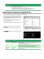
Referring to Property of Logical Drive
For the information on a Logical Drive, see the property of the Logical Drive.
To display the property of Logical Drive by RAID Viewer,
click the Logical Drive whose information is to be seen on
the Tree View and click [Properties] on the pull-down menu
of menu item [File].
The [Logical Drive Properties] dialog box contains the
[General] and [Option] tabs.
The [General] tab indicates the property of the Logical Drive.
The [Option] tab allows you to see the settings of the
Logical Drive.
You can change the settings in the Advanced Mode.
Use "property" command to see the property of a Logical
Drive by raidcmd.
Item
RAID Viewer
> raidcmd property -tg=ld -c=1 -l=1
RAID Controller #1 Logical Drive #1
ID
: 0
: 1, 2, 3
Physical Device Number
: 1 (order 1/1)
Disk Array Information
: RAID 5
RAID Level
Capacity
: 20GB
Stripe Size
: 64KB
Cache Mode (Current)
: Write Back
Cache Mode (Setting)
: Auto Switch
Status
: Online
>
Item
raidcmd
Description
Number
RAID Controller #X
Logical Drive #Y
Indicates the management number (logical address) of the Logical Drive in the
Universal RAID Utility.
The Universal RAID Utility assigns a number beginning with 1 in
correspondence with the value of [ID].
ID
ID
Indicates the original identification value of the Logical Drive. Use this value to
create Logical Drives managed by the BIOS utility of the RAID Controller
correspond with those managed by the Universal RAID Utility.
Physical Device
Number
Physical Device
Number
Indicates the numbers of Physical Devices configuring the Disk Array in which
the Logical Drive exists.
42
Item
RAID Viewer
Item
raidcmd
Description
Disk Array
Information
Disk Array
Information
Indicates the number of the Disk Array in which the Logical Drive exists and the
information on the location in the Disk Array. The information is displayed in
the following format.
<RAID Viewer>
Disk Array number (sequence number starting from the top / sequence number
of Logical Drive in Disk Array)
<raidcmd>
Disk Array number (order sequence number starting from the top / sequence
number of Logical Drive in Disk Array)
RAID Level
RAID Level
Indicates the RAID Level of the Logical Drive.
The value can be RAID 0, RAID 1, RAID 5, RAID 6, RAID 00, RAID 10, RAID 1E,
RAID 50 or RAID 60.
Capacity
Capacity
Indicates the capacity of the Logical Drive in GB.
Stripe Size
Stripe Size
Indicates the Stripe Size of the Logical Drive.
The value can be 1KB, 2KB, 4KB, 8KB, 16KB, 32KB, 64KB, 128KB, 256KB,
512KB, or 1024KB.
Cache Mode
(Current)
Cache Mode
(Current)
Indicates the current value of the mode of writing data to the cache memory
installed in the RAID Controller.
Three possible modes are as follows:
Write Back: Writes data to the cache memory asynchronously.
Write Through: Writes data to the cache memory synchronously.
Cache Mode
(Setting)
Cache Mode
(Setting)
Indicates the mode of writing data to the cache memory installed in the RAID
Controller.
Three possible modes are as follows:
Auto Switch: Switches the mode automatically between Write Back and Write
Through depending on the existence and/or status of battery.
Write Back: Writes data to the cache memory asynchronously.
Write Through: Writes data to the cache memory synchronously.
Status
Status
Indicates the status of the Logical Drive.
Three possible status are as follows:
Online: Indicates that the redundancy of the Logical Drive is retained.
Degraded: Indicates that the redundancy of the Logical Drive is lost or
degraded. Accessing to the Logical Drive is enabled.
Offline: Indicates that the Logical Drive is offline and accessing to the Logical
Drive is disabled.
Each RAID Controller supports specific RAID Levels and Stripe Sizes. Unsupported items
indicate space or do not appear in the list.
Each RAID Controller supports specific Cache Modes. Unsupported Cache Modes do not
appear.
Each RAID Controller supports specific items appearing on the Property tab of the
Logical Drive and specific items whose settings can be changed. Unsupported items
indicate space or do not appear in the list.
The status of a Logical Drive is defined depending on the RAID Level and the number of
Physical Devices failed.
If the RAID Level is RAID 10 or RAID 50 and two Physical Devices are failed, the status will
be [Degraded] or [Offline] depending on the failed Physical Devices.
43
Number of failed Physical
Devices
0
1
2
3 or more
RAID 0
Online
Offline
Offline
Offline
RAID 1
Online
Degraded
Offline
-
RAID 5
Online
Degraded
Offline
Offline
RAID 6
Online
Degraded
Degraded
Offline
RAID 10
Online
Degraded
Degraded/Offline
Offline
RAID 50
Online
Degraded
Degraded/Offline
Offline
Referring to Property of Physical Device
For the information on a Physical Device, see the property of the Physical Device.
To display the property of Physical Device by RAID Viewer,
click the Physical Device whose information is to be seen on
the Tree View and click [Properties] on the pull-down menu of
menu item [File].
The [General] tab indicates the property of the Physical
Device.
Use "property" command to see the property of a physical
drive by raidcmd.
Item
RAID Viewer
Item
raidcmd
> raidcmd property -tg=pd -c=1 -p=1
RAID Controller #1 Physical Device #1
ID
: 0
Enclosure
: 1
: 1
Slot
: HDD
Device Type
Interface
: SAS
Vendor/Model
: SEAGATE ST936751SS
Firmware Version
: 0001
Serial Number
: 3PE073VM
Capacity
: 33GB
Status
: Online
: Normal
S.M.A.R.T.
>
Description
Number
RAID Controller #X
Physical Device #Y
Indicates the management number (logical address) of the Physical Device in
the Universal RAID Utility.
The Universal RAID Utility arranges Physical Devices in the ascending order of
IDs and assigns a number beginning with 1 sequentially to the Physical
Devices.
ID
ID
Indicates the original identification value of the Physical Device. Use this value
to make Physical Devices managed by the BIOS utility of the RAID Controller
correspond with those managed by the Universal RAID Utility.
The format of the ID varies depending on the types of RAID Controllers.
44
Item
RAID Viewer
Item
raidcmd
Description
Enclosure
Enclosure
Indicates the number of Enclosure inserted Physical Device.
This value is a number beginning with 1.
Slot
Slot
Indicates the number of Slot inserted Physical Device.
This value is a number beginning with 1.
Device Type
Device Type
Indicates the type of Physical Device.
Four possible types are as follows:
HDD : Hard Disk Drive
HDD(SSD) : Solid State Drive
Tape Drive : Tape Drive
CD/DVD : CD drive or DVD drive
Interface
Interface
Indicates the type of the interface to which the Physical Device is connected.
Two possible types are as follows:
SAS : Serial Attached SCSI
SATA : Serial ATA
Vendor/Model
Vendor/Model
Indicates the vendor and model name of the Physical Device.
Firmware Version
Firmware Version
Indicates the version of the Physical Device.
Serial Number
Serial Number
Indicates the serial number of the Physical Device.
This item is indicated when [Device Type] item is [HDD] or [HDD(SSD)].
Capacity
Capacity
Indicates the capacity of the Physical Device in GB.
This item is indicated when [Device Type] item is [HDD] or [HDD(SSD)].
Status
Status
Indicates the status of the Physical Device.
Five possible status are as follows:
Online: Indicates that the Physical Device is incorporated into a Logical Drive to
operate normally.
Failed: Indicates that the Physical Device is incorporated into a Logical Drive
but is failed.
Rebuilding: Indicates that the Physical Device is rebuilding.
Hot Spare: Indicates that the Physical Device is set as a Hot Spare.
Ready: Indicates that the Physical Device is not incorporated into a Logical
Drive.
This item is indicated when [Device Type] item is [HDD] or [HDD(SSD)].
Hot Spare
Information
Hot Spare
Information
Indicates the Hot Spare mode of the Physical Device if it is specified as a Hot
Spare. Two possible modes are as follows:
Global: The Physical Device can be used as a Hot Spare of any Disk Array in the
RAID Controller.
Dedicated: The Physical Device can be used as a Hot Spare of the specified
Disk Array. Also indicates the number of the specified Disk Array.
This item is indicated when [Device Type] item is [HDD] or [HDD(SSD)].
S.M.A.R.T.
S.M.A.R.T.
Indicates the diagnosis result of S.M.A.R.T.(Self-Monitoring, Analysis and
Reporting Technology) function. Two possible statuses are as follows.
Normal: Does not detect any error caused by the S.M.A.R.T. function.
Detected: Detects one or more errors caused by the S.M.A.R.T. function.
This item is indicated when [Device Type] item is [HDD] or [HDD(SSD)].
Each RAID Controller supports specific items appearing on the Property tab of the
Physical Device and specific items whose settings can be changed. Unsupported items
indicate space or do not appear in the list.
Even if Physical Device does not break down when you execute Make Offline, [Status]
item is changed to [Failed].
Referring to Property of Disk Array
For the information on a Disk Array, see the property of the Disk Array.
45
To display the property of Disk Array by RAID Viewer, click the
Disk Array whose information is to be seen on the Tree View
and click [Properties] on the pull-down menu of menu item
[File].
The [General] tab indicates the property of the Disk Array.
Use "property" command to see the property of a Disk
Array by raidcmd.
Item
RAID Viewer
> raidcmd property -tg=da -c=1 -a=1
RAID Controller #1 Disk Array #1
ID
: 0
: 1, 2, 3
Physical Device Number
Capacity
: 67GB
Unused Capacity
: 47GB
>
Item
raidcmd
Description
Number
RAID Controller #X
Disk Array #Y
Indicates the management number (logical address) of the Disk Array in the
Universal RAID Utility.
ID
ID
Indicates the original identification value of the Disk Array. Use this value to
create Disk Array managed by the BIOS utility of the RAID Controller
correspond with those managed by the Universal RAID Utility.
Physical Device
Number
Physical Device
Number
Indicates the numbers of Physical Devices configuring the Disk Array.
Capacity
Capacity
Indicates the total capacity of Physical Device in Disk Array in GB.
Unused Capacity
Unused Capacity
Indicates the total capacity of unused area in the Disk Array in GB.
Checking Execution Status of Operation
RAID Viewer and raidcmd allows the checking execution status of operation in the RAID System.
To check the execution status of operation by RAID Viewer, use Operation View on RAID Viewer. See "Operation View"
for detail.
To check the execution status of operation by raidcmd, use
"oplist" command. The following operations are displayed
by "oplist" command. The target components and status
appear in operations:
Initialize
> raidcmd oplist
RAID Controller #1
Logical Drive #1 : Consistency Check (52%)
Logical Drive #2 : Initialize (33%)
Physical Device #1(0): Rebuild (99%)
RAID Controller #2
Logical Drive #1 : Consistency Check (2%)
Physical Device #2(1): Rebuild (22%)
>
Rebuild
Consistency Check
The operation performed at execution of the raidcmd appears. Terminated operations do not appear. For the results of
terminated operations, see the RAID Log and/or properties.
Physical Device has two numbers on oplist.
Physical Device #M(N)
M : The number of Physical Device
N : ID of Physical Device
46
Updating Information of RAID System
The management information of RAID System managed by the Universal RAID Utility is corrected by the raidsrv
service at the following timings:
Starting raidsrv service
Receiving an event such as change of RAID System status or change of execution status of an operation having
occurred
To update the management information of the RAID system to the latest, collect the newest information of all RAID
System by the RAID Viewer and raidcmd.
RAID Viewer
Use [Rescan] in [File] menu.
Step 1
Start the RAID Viewer. Click [Rescan] in [File] menu. The raidsrv service
acquires the information on the RAID System from the RAID System again and
updates the management information to the latest.
raidcmd
Use "rescan" command.
Step 1
Execute "rescan" command. The raidsrv
service acquires the information on the RAID System
from the RAID System again and updates the
management information to the latest.
> raidcmd rescan
>
1
Referring to RAID System Operation Log
Operations done for RAID Systems and events occurred in the RAID Systems are registered to the RAID Log of the
Universal RAID Utility. See "Logging Events to RAID Log" for detail.
In case of the operating system is Windows, use Log Viewer to refer to RAID Log
The information saved in the RAID Log at the start of the Log Viewer appears on it. To
update the information, click [Refresh] on the pull-down menu of menu item [File]. The
Log Viewer acquires the RAID Log again and updates the displayed information to the
latest.
In case of the operating system is Linux, use text editor or otherwise to refer to RAID Log.
47
Configuration of RAID System
This chapter describes the configuration of a RAID System by using the Universal RAID Utility.
The Universal RAID Utility provides a variety of functions depending on purposes.
Would like to make
Hot Spare as
measures against
failure of Physical
Device.
Allows Global or Dedicated
Hot Spare to be made
without errors.
Would like to
configure RAID
System easily due to
no expert knowledge
of RAID System.
See "Making Hot Spare".
See "Configuring RAID
System Easily".
Provides "Easy Configuration"
allowing RAID System to be
configured without expert
knowledge of RAID System.
See "Creating Logical
Drive Easily".
Would like to add a
Logical Drive easily.
Allows Logical Drive to be
made only by setting two
selection items.
Would like to specify
configuration of
Logical Drive closely
or create more than
one Logical Drive at a
time.
Would like to delete
unnecessary Logical
Drive. However, it is
anxious about
destruction of system
by mistake.
See "Creating Logical
Drive Freely".
Allows information on
Logical Drive to be set
closely or more than one
Logical Drive to be created
at a time at will.
See "Deleting Logical
Drive".
Disables Logical Drive
containing partition to be
deleted by mistake.
Figure 8 RAID System configuration functions
48
Making Hot Spare
The Universal RAID Utility can make a Hot Spare to be replaced with a Physical Device in which a failure occurs.
Hot spares can have the following two modes.
Mode
Description
Global (Hot Spare)
Available as a Hot Spare of every Disk Array for a single RAID Controller.
Dedicated (Hot Spare)
Available as a Hot Spare of a specific Disk Array for a single RAID Controller.
In either mode, note the following to have a Hot Spare operate normally.
A Hot Spare can operate properly only for a Disk Array configured with Physical Devices of the same interface
type and the same device type.
A Hot Spare can operate properly only if the Hot Spare has the capacity equal to or larger than that of the
Physical Device in which a failure occurs.
A Physical Device in which a S.M.A.R.T. error is detected cannot be used as a Hot Spare.
About Global Hot Spare
Global Hot Spare is a Hot Spare of every Logical Drives for a single RAID Controller.
Ex.1 : If you make the Global Hot Spare on the RAID Controller which has Logical Drive #1 and #2, the Global
Hot Spare is a Hot Spare of Logical Drive #1 and #2.
Logical Drive Logical Drive
#1
#2
Global Hot
Spare
Figure 9 Global Hot Spare 1
Ex.2 : If you create the Logical Drive #3 on the RAID System of Ex.1, the Global Hot Spare is a Hot Spare for the
Logical Drive #3 too.
Logical Drive Logical Drive
#1
#2
Logical Drive
#3
Global Hot
Spare
Figure 10 Global Hot Spare 2
49
About Dedicated Hot Spare
Dedicated Hot Spare is a Hot Spare of specified Logical Drives for a single RAID Controller. The Dedicated Hot
Spare features the following:
Dedicated Hot Spare is a Hot Spare of specified Logical Drives.
One Dedicated Hot Spare can be a Hot Spare of one or more Logical Drives.
One or more Dedicated Hot Spare can be a Hot Spare of one or more Logical Drives.
Dedicated Hot Spares cannot be created in a Disk Array containing Logical Drives with
the RAID Level being RAID 0.
Dedicated Hot Spares can not be created in a Disk Array which does not have any Logical
Drive.
Dedicated Hot Spare can be created by a Physical Device as which a Physical Device of
the same Interface Type and Device Type to create the Disk Array.
Ex 1 : You make the Dedicated Hot Spare on the RAID Controller which has Logical Drive #1 and #2. If you
specify only the Logical Drive #1 as the target Logical Drive, the Dedicated Hot Spare is a Hot Spare of Logical
Drive #1.
Logical Drive Logical Drive
#1
#2
Dedicated
Hot Spare
Figure 11 Dedicated Hot Spare 1
Ex 2 : In case of the RAID System in Ex1, If you specify the Logical Drive #1 and #2 as the target Logical Drive,
the Dedicated Hot Spare is a Hot Spare of Logical Drive #1 and #2.
Logical Drive
#1
Logical Drive
#2
Dedicated
Hot Spare
Figure 12 Dedicated Hot Spare 2
Ex 3 : In case of the RAID System in Ex1, you can add more Dedicated Hot Spare . If you add the Dedicated Hot
Spare #2 to the Logical Drive #1, the both Dedicated Hot Spare are the Hot Spare for the Logical Drive #1.
50
Logical Drive Logical Drive
#1
#2
Dedicated
Hot Spare #1
Dedicated
Hot Spare #2
Figure 13 Dedicated Hot Spare 3
Ex 4 : In case of the RAID System in Ex2, you can add more Dedicated Hot Spare likely Ex2. If you add the
Dedicated Hot Spare to the Logical Drive #1 and #2, the both Dedicated Hot Spare are the Hot Spare for the
Logical Drive #1 and #2.
Logical Drive Logical Drive
#1
#2
Dedicated
Hot Spare #1
Dedicated
Hot Spare #2
Figure 14 Dedicated Hot Spare 4
Making Global Hot Spare
The procedure of making a Global Hot Spare is described below.
RAID Viewer
Use [Make Global Hot Spare] in [Control] menu.
Step 1
Start the RAID Viewer. Click a Physical Device with [Status] being [Ready] on the Tree View.
Step 2
Select [Hot Spare] on the pull-down
menu of menu item [Control] and click [Make Global
Hot Spare].
Step 3
If you see the property of the Physical
Device after making a Global Hot Spare, you can
find that the value of [Status] is set to [Hot Spare]
and item [Hot Spare Information] appears newly
with value [Global].
51
raidcmd
Use "hotspare" command.
Step 1
Execute "hotspare" command with -mr
option and the following parameters.
Number of the RAID Controller containing the Physical
Device with which a Hot Spare is made
Number of the Physical Device with which a Global Hot
Spare is made
Step 2
If you see the property of the Physical
Device after making the Global Hot Spare, you find
that the value of [Status] is changed to [Hot Spare]
and new item [Hot Spare Information] appears with
value [Global].
Do you continue ? [yes(y) or no(n)] : yes
>
> raidcmd property -tg=pd -c=1 -p=6
RAID Controller #1 Physical Device #6
ID
: 5
Enclosure
: 1
Slot
: 6
Device Type
: HDD
Interface
: SAS
Vendor/Model
: Seagate ST12345678
Firmware Version
: BK09
Serial Number
: 1111
Capacity
: 146GB
Status
: Hot Spare
Hot Spare Information
: Global
S.M.A.R.T.
: Normal
>
Making Dedicated Hot Spare
The procedure of making a Dedicated Hot Spare is described below.
RAID Viewer
Use [Make Dedicated Hot Spare] in [Control] menu.
Step 1
1
> raidcmd hotspare -c=1 -p=6 -mr=make
Make Global Hot Spare.
Start the RAID Viewer. Click a Physical Device with [Status] being [Ready] on the Tree View.
Step 2
Select [Hot Spare] on the pull-down
menu of menu item [Control] and click [Make
Dedicated Hot Spare].
Step 3
The [Make Dedicated Hot Spare] dialog
box appears. Check the check box of the Disk Array
for which a Dedicated Hot Spare is to be made. The
Dedicated Hot Spare may be made for more than
one Disk Array. However, it cannot be made for a
Disk Array requiring a capacity larger than [Capacity
of selected Physical Device].
Click [OK] to make the Dedicated Hot Spare.
Step 4
If you see the property of the Physical
Device after making a Dedicated Hot Spare, you can
find that the value of [Status] is set to [Hot Spare]
and item [Hot Spare Information] appears newly
with value [Dedicated (Disk Array #X)].
raidcmd
Use "hotspare" command.
52
2
Step 1
Execute "hotspare" command with -mr
option and the following parameters.
1
> raidcmd hotspare -c=1 -p=6 -mr=make -a=2
Make Dedicated Hot Spare.
Number of the RAID Controller containing the Physical
Device with which a Hot Spare is made
Number of the Physical Device with which a Dedicated
Hot Spare is made(The capacity of the Physical Device
should be equal to or larger than any Physical Device
used by the target Disk Array)
Number of the target Disk Array using the Dedicated Hot
Spare
Step 2
If you see the property of the Physical
Device after making the Dedicated Hot Spare, you
find that the value of [Status] is changed to [Hot
Spare] and new item [Hot Spare Information]
appears with value [Dedicated].
Do you continue ? [yes(y) or no(n)] : yes
>
> raidcmd property -tg=pd -c=1 -p=6
RAID Controller #1 Physical Device #6
ID
: 5
Enclosure
: 1
Slot
: 6
Device Type
: HDD
Interface
: SAS
Vendor/Model
: Seagate ST12345678
Firmware Version
: BK09
Serial Number
: 1111
Capacity
: 146GB
Status
: Hot Spare
Hot Spare Information
: Dedicated (Disk Array #2)
S.M.A.R.T.
: Normal
>
2
Removing Hot Spare
The procedure of removing a Hot Spare is described below.
RAID Viewer
Use [Remove Hot Spare] in [Control] menu.
Step 1
Start the RAID Viewer. Click a Physical Device with [Status] being [Hot Spare] on the Tree View.
Step 2
Select [Hot Spare] on the pull-down
menu of menu item [Control] and click [Remove Hot
Spare].
Step 3
If you see the property of the Physical
Device after removing it from the Hot Spare, you can
find that the value of [Status] is set to [Ready] and
item [Hot Spare Information] disappears.
raidcmd
Use "hotspare" command.
Step 1
Execute "hotspare" command with -mr
option and the following parameters.
1
> raidcmd hotspare -c=1 -p=6 -mr=remove
Remove Hot Spare.
Number of the RAID Controller containing the Physical
Device from which the Hot Spare is removed
Number of the Physical Device from which the Hot Spare
is removed
Step 2
If you see the property of the Physical
Device after removing the Hot Spare, the value of
[Status] is changed to [Ready] and item [Hot Spare
Information] disappears.
53
Do you continue ? [yes(y) or no(n)] : yes
>
> raidcmd property -tg=pd -c=1 -p=6
RAID Controller #1 Physical Device #6
ID
: 5
Enclosure
: 1
Slot
: 6
Device Type
: HDD
Interface
: SAS
Vendor/Model
: Seagate ST12345678
Firmware Version
: BK09
Serial Number
: 1111
Capacity
: 146GB
Status
: Ready
S.M.A.R.T.
: Normal
>
2
Configuring RAID System Easily
The Universal RAID Utility supports the Easy Configuration function allowing configurations such as creating Logical
Drive and making a Hot Spare to be provided in the state where unused Physical Devices are connected to RAID
Controllers.
If you decide the number of Physical Devices used for data storage (or the number of Physical Devices configuring
Logical Drives) and the number of Physical Devices used as Hot Spares among unused Physical Devices connected to
RAID Controllers, the Universal RAID Utility automatically configure the RAID System.
The benefits of configuring a RAID System by using the Easy Configuration are as follows. The Universal RAID Utility
performs the jobs which must be examined and manipulated to configure a RAID System instead.
Allowing a RAID System to be configured only by specifying three items, or a RAID Controller, the number of
Physical Devices used for Logical Drives and the number of Logical Drives to be created.
Allowing the Universal RAID Utility to set all the items associated with Logical Drives (including RAID Level,
Capacity, and Stripe Size) automatically.
Allowing more than one Logical Drive to be created at a time.
Making Dedicated Hot Spares for Logical Drives automatically created by Universal RAID Utility if Physical
Devices are left for Hot Spares.
Procedure of Easy Configuration of RAID System
The following describes the procedure of configuring a RAID System easily.
RAID Viewer
Use [Easy Configuration] in [Tool] menu.
Step 1
Connect Physical Devices used for Easy Configuration to the RAID Controller at this timing if required. If the
Physical Devices are connected completely, start the RAID Viewer.
Step 2
Click [Easy Configuration] on the pull-down menu of menu item
[Tool].
Step 3
The [Easy Configuration] wizard is
started. In step 1/3, select the RAID Controller to be
configured by clicking it. Then click [Next].
In the [RAID Controller] area, RAID Controllers which
do not meet the conditions on Easy Configuration do
not appear.
54
Step 4
In step 2/3, specify the number of
Physical Devices used by Logical Drives (or the
number of Physical Devices used for data storage)
and the number of Logical Drives created in the
RAID Controller. If Physical Devices of different
interface types or device type exist, specify the
number of Physical Devices in each type. After the
specification, click [Next].
Step 5
Step 3/3 shows the configuration of the
RAID System to be configured by the Easy
Configuration. To the RAID System according to the
displayed information, click [OK]. To change the
configuration, click [Back].
Step 6
If you click [OK] in step 3/3, then the
RAID System will be configured. After the Logical
Drives are created and the makings of Hot Spares
are completed, [Completing the "Easy
Configuration" Wizard] appears. Now creating the
Logical Drives and making Hot Spares is completed.
After the wizard is closed, see the Tree View to
check the configuration. However, the Initialize of
the Logical Drives having been created may not be
completed. The progress and result of initializing the
Logical Drives can be checked on the Operation
View.
raidcmd
Use "econfig" command.
Step 1
Connect Physical Devices used for Easy Configuration to the RAID Controller at this timing if required.
Step 2
Execute "econfig" command.
Step 3
Specify the conditions on Easy Configuration.
In step 1/3, select the RAID Controller to be configured. Enter the RAID Controller number to be configured.
55
Step 4
In step 2/3, specify the number of
Physical Devices used for Logical Drive(s) ("Physical
Device count using Logical Drive(s)") and the number
of Logical Drives to be created in the RAID Controller
("Making Logical Drive count"). If Physical Devices of
different Interface Types or Device Type exist, specify
the number of Physical Devices in each type (in the
example shown to the right, proper settings are
provided for Physical Devices of the SAS interface. If
other Physical Devices of different types exist,
perform the operation in each type).
Step 5
Step 3/3 shows the configuration of the
RAID System to be configured by the Easy
Configuration. To configure the RAID System
according to the displayed information, type "yes". To
change the configuration, type "no".
If you type "yes", the raidcmd executes the
configuration of the RAID System and terminates
normally. Making Logical Drives and Hot Spares is
now completed. See the property of each component
to check the configuration. However, the Initialize of
the Logical Drives having been created may not be
completed. The progress and result of initializing the
Logical Drives can be checked by using "oplist"
command.
2
> raidcmd econfig
Step 1/3 : Select RAID Controller
RAID Controller #1 MegaRAID SAS PCI Express(TM) ROMB
RAID Controller #2 LSI Corporation MegaRAID SAS 8408E
RAID Controller [1-2] : 1
3
Step 2/3 : Set the contents of configuration
<Physical Device (Type : SAS)>
Unused Physical Device count
: 7
Physical Device count using Logical Drive(s) [ 2- 7] : 6
Hot Spare count
: 1
Do you continue ? [yes(y) or no(n)] : y
Maximum Logical Drive count
Creating Logical Drive count [ 1- 2]
4
: 2
: 1
Do you continue ? [yes(y) or no(n)] : y
Step 3/3 : Confirm the contents of configuration
RAID Controller #1(0) LSI MegaRAID SAS 8202E
Disk Array #1
LD #1 [Online] RAID 5
PD #1(0) [Online] SAS-HDD
PD #2(1) [Online] SAS-HDD
PD #3(2) [Online] SAS-HDD
PD #7(6) [Dedicated Hot Spare] SAS-HDD
Disk Array #2
LD #2 [Online] RAID 5
PD #4(3) [Online] SAS-HDD
PD #5(4) [Online] SAS-HDD
PD #6(5) [Online] SAS-HDD
PD #7(6) [Dedicated Hot Spare] SAS-HDD
Disk Array #3
LD #3 [Online] RAID 1
PD #8(7) [Online] SATA-HDD
PD #9(8) [Online] SATA-HDD
PD #10(9) [Dedicated Hot Spare] SATA-HDD
<Caution>
Create Logical Drive #2 with different Physical Devices of
a capacity. Therefore, Logical Drive capacity is decided by
the smallest Physical Device of capacity.
Run the above configuration.
Initialize all of Logical Drive after creating them. You can
see the progress and the result of initialization by "oplist"
and "property" commands.
Do you continue ? [yes(y) or no(n)] : yes
>
5
RAID Controller and Physical Device has two numbers in Step 3/3.
RAID Controller #A (B)
Physical Device #C (D)
A : The number of RAID Controller, B : ID of RAID Controller
C : The number of Physical Device, D : ID of Physical Device
RAID Controller Enabling Easy Configuration to Be Executed
Any RAID Controller enabling Easy Configuration to be executed must meet the following conditions.
Allowing Dedicated Hot Spares to be made, and
Connecting with more than one unused Physical Device.
Physical Devices Available for Easy Configuration
Only unused Physical Devices are available for Easy Configuration. Unused Physical Devices are those with their
[Status] being [Ready].
56
Creating Logical Drives by Easy Configuration
Logical Drives created by Easy Configuration are described below.
RAID Levels and the number of Logical Drives allowed to be created
The RAID Level of a Logical Drive created by Easy Configuration should be RAID 1 or RAID 5. Whether RAID
1 or RAID 5 is used is defined by RAID Levels supported by the RAID Controller and the number of Physical
Devices used by the Logical Drive.
The number of Logical Drives allowed to be created is also defined by the similar conditions.
RAID Controller supporting RAID Levels RAID 1 and RAID 5
Number of Physical
Devices used by Logical
Drive
RAID Level of Logical Drive
Number of Logical Drives allowed to be created
2
RAID 1
1
3-5
RAID 5
1
6 or more
RAID 5
Number of Physical Devices used by Logical Drive / 3
Number of Physical
Devices used by Logical
Drive
RAID Level of Logical Drive
Number of Logical Drives allowed to be created
2 or more
RAID 1
Number of Physical Devices used by Logical Drive / 2
RAID Controller supporting RAID 1 only
The Easy Configuration can only create Logical Drives of RAID 1 or RAID 5.
Physical Devices used for Logical Drives
Physical Devices of lower Physical Device Numbers are used preferentially for Logical Drives to be created
excluding those for making Hot Spares.
Ex. : If Physical Devices #1 - #7 can be used for Easy Configuration and Physical Device #3 is used as a Hot
Spare, Logical Drives #1 and #2 are created with Physical Devices #1 and #2 having lower Physical Device
Physical
Device #1
Physical
Device #2
Physical
Device #3
Hot Spare
Physical
Device #4
Physical
Device #5
Logical
Drive #1
Physical
Device #6
Physical
Device #7
Logical
Drive #2
Numbers and Physical Devices #5, #6 and #7, respectively.
Figure 15 Assigning Physical Devices in Easy Configuration 1
If more than one Logical Drive are created and the number of Physical Devices configuring a Logical Drive is
not equal to others, a larger number of Physical Devices should be assigned to a Logical Drive having a
smaller logical number.
57
Ex.: If Physical Devices #1 - #7 can be used for Easy Configuration and two Logical Drives are created,
Logical Drives #1 and #2 are created with four Physical Devices #1 - #4 and three Physical Devices #5 - #7,
respectively.
Physical
Device #1
Physical
Device #2
Physical
Device #3
Physical
Device #4
Physical
Device #5
Logical
Drive #1
Physical
Device #6
Physical
Device #7
Logical
Drive #2
Figure 16 Assigning Physical Devices in Easy Configuration 2
Physical Devices in which S.M.A.R.T. errors are detected cannot be used to create Logical
Drives.
Capacity of Logical Drive
The capacity of a Logical Drive to be created is defined by the RAID Level and the capacities of Physical
Devices used for the Logical Drive.
The Easy Configuration uses the entire areas of the Physical Devices to create a Logical Drive.
When a single Logical Drive is created by using Physical Devices of different capacities, the smallest
capacity is applied among those of the Physical Devices.
Ex.: If Physical Devices #1 - #7 of different capacities can be used in Easy Configuration to create two
Logical Drives, use Physical Devices #1 - #4 and #5 - #7 to create Logical Drives #1 and #2, respectively.
The capacity of each Logical Drive is defined by the smallest capacity among those of the Physical Devices
for the Logical Device.
Physical
Device #1
50GB
Physical
Device #2
50GB
Logical
Drive #1
150GB
RAID 5
Physical
Device #3
150GB
Physical
Device #4
100GB
Only 50GB is used in
each Physical Device
(#3 and #4) because
the smallest capacity is
50GB (remaining
capacities 100GB and
50GB are not used in #3
and #4, respectively).
Physical
Device #5
100GB
Physical
Device #6
100GB
Logical
Drive #2
200GB
RAID 5
Only 100GB can be
used in Physical
Device #7 because
the smallest capacity
is 100GB in the
Physical Devices.
(Remaining 50GB is
not used.)
Figure 17 Capacities of Logical Drives in Easy Configuration
58
Physical
Device #7
150GB
Items set for Logical Drive
The values of other selection items set for a Logical Drive to be created are defined as shown in the table
below.
Selection item
Value
Stripe Size
Uses the default value set for the RAID Controller. (The value varies depending on the
type of the RAID Controller.)
Cache Mode
Uses the default value set for the RAID Controller. (The value varies depending on the
type of the RAID Controller.)
Initialization Mode
Full
Making Hot Spares by Easy Configuration
This section describes the information on Hot Spares to be made by the Easy Configuration.
Number of Hot Spares
The number of Hot Spares is defined by the number of unused Physical Devices connected to the RAID
Controller and the number of Physical Devices used for Logical Drives. The number of Hot Spares results
from subtracting [Number of Physical Devices specified for Logical Drives] from [Unused Physical Device
count] in step 2/3 of the [Easy Configuration] wizard of RAID Viewer or "econfig" command of raidcmd.
Physical Devices used as Hot Spares
Physical Devices of larger capacities are preferentially used as Hot Spares. Among Physical Devices of the
same capacity, Physical Devices of larger Physical Device Numbers are preferentially used as Hot Spares.
Ex.: For the example shown below, Physical Devices #1 - #7 can be used in Easy Configuration to make two
Hot Spares. Three Physical Devices have the largest capacity of 150GB. Accordingly, use Physical Devices
#5 and #6 of larger Physical Device Numbers among the three Physical Devices as Hot Spares.
Physical
Device #1
100GB
Physical
Device #2
100GB
Physical
Device #3
150GB
Physical
Device #4
100GB
Physical
Device #5
150GB
Physical
Device #6
150GB
Hot Spare
Hot Spare
Physical
Device #7
100GB
Figure 18 Assigning Hot Spares in Easy Configuration
Physical Devices in which S.M.A.R.T. errors are detected cannot be used to make Hot
Spares.
Modes of Hot Spares
The Easy Configuration can only make Dedicated Hot Spares but cannot make Global Hot Spares.
If more than one Logical Drive is created, the Dedicated Hot Spare can be used for all Logical Drives to be
created.
59
Ex.: If Physical Devices #1 - #7 are used in Easy Configuration to create two Logical Drives and a single Hot
Spare, the Hot Spare will be the Dedicated Hot Spare for each Logical Drive.
Physical Devices
#1, #2 and #3
Physical Devices
#4, #5 and #6
Physical
Device #7
Logical
Drive #1
Logical
Drive #2
Dedicated
Hot Spare
Figure 19 Making Dedicated Hot Spare in Easy Configuration 1
Ex.: If Physical Devices #1 - #8 are used in Easy Configuration to create two Logical Drives and two Hot
Spares, Hot Spares #1 and #2 will be the Dedicated Hot Spares for Logical Drives #1 and #2, respectively.
Physical Devices
#1, #2 and #3
Physical Devices
#4, #5 and #6
Physical
Device #7
Physical
Device #8
Logical
Drive #1
Logical
Drive #2
Hot Spare
#1
Hot Spare
#2
Figure 20 Making Dedicated Hot Spares in Easy Configuration 2
60
Creating Logical Drive Easily
The Universal RAID Utility supports "Create Logical Drive - Simple Mode" in which a Logical Drive can be created only
by selecting two selection items according to the guide.
"Create Logical Drive - Simple Mode" allows you to create a Logical Drive only by specifying two selection items, or the
RAID Level of the Logical Drive and Physical Devices to be used.
The benefits of creating a Logical Drive with "Create Logical Drive - Simple Mode" are as follows. The Universal RAID
Utility defines selection items which you should examine to create a Logical Drive instead of you.
Allowing a Logical Drive to be created only by specifying two selection items (RAID Level and Physical Devices
to be used).
Allowing the Universal RAID Utility to set all setting items (including Capacity and Stripe Size) other than the
RAID Level and Physical Devices to be used automatically.
Operation Procedure of "Create Logical Drive - Simple
Mode"
This section describes the procedure of creating a Logical Drive by "Create Logical Drive - Simple Mode".
RAID Viewer
Use [Create Logical Drive (Simple)] in [Control] menu.
Step 1
Connect Physical Devices used for a Logical Drive to the RAID Controller at this timing if required. If the
Physical Devices are connected completely, start the RAID Viewer.
Step 2
Click the RAID Controller on the Tree View,
select [Create Logical Drive] on the pull-down menu of
menu item [Control], and click [Simple...].
If only a single unused Physical Device exists in the RAID Controller, "Create Logical Drive Simple Mode" is disabled.
Step 3
The [Create Logical Drive (Simple)]
wizard is started.
In step 1/3, select the RAID Level of the Logical
Drive to be created. After the selection, click [Next].
61
Step 4
In step 2/3, select Physical Devices to be
used to create the Logical Drive. If Physical Devices of
different types exist in the RAID Controller, click the
type to be used on [Type]. Next, check the check
boxes of Physical Devices to be used on [Physical
Device]. You must select Physical Devices to be used
by the number allowing the RAID Level selected in
Step 1/3 to be created. After selecting Physical
Devices properly, click [Next].
Step 5
Step 3/3 indicates the information on
the Logical Drive to be created. Click [OK] to create
the Logical Drive with the functions. Click [Back] to
change one or more functions.
Step 6
In step 3/3, click [OK] to create the
Logical Drive. After the Logical Drive is created
completely, [Completing the "Create Logical Drive
(Simple)" Wizard] appears. Now the Logical Drive
has been created completely. Close the wizard and
check the information on the Logical Drive on the
Tree View. However, the Logical Drive having been
created may not be initialized yet. Check the
progress or result of the Initialize of the Logical
Drive on the Operation View.
raidcmd
Use "mklds" command.
Step 1
Connect Physical Devices used for a Logical Drive to the RAID Controller at this timing if required.
Step 2
Execute "mklds" command with the
following parameters.
> raidcmd mklds -c=1 -p=3,4,5 -rl=5
raidcmd creates Logical Drive #2.
Number of the RAID Controller in which a Logical Drive is
created
Numbers of the Physical Devices with which a Logical
Drive is created (The required number of Physical
Devices varies depending on the RAID Level of the
Logical Drive to be created).
RAID Level at which a Logical Drive is made ("Create
Logical Drive - Simple Mode" allows a Logical Drive with
RAID Level being RAID 1 or RAID 5 to be created)
Step 3
Do you continue ? [yes(y) or no(n)] : y
3
raidcmd created Logical Drive #2, and started to initialize
it.
You can see the progress and the result of initialize by
"oplist" and "property" commands.
>
Type "yes" to reply to the confirmation message. Then a Logical Drive is created.
62
2
Step 4
After the Logical Drive is created completely, the raidcmd terminates normally. The Logical Drive has been
created completely. You can check the information on the Logical Drive by using "property" command. However, the
Initialize of the Logical Drive having been created may not be completed. The progress and result of initializing the
Logical Drive can be checked by using "oplist" command.
Physical Devices Available for "Create Logical Drive - Simple
Mode"
Unused Physical Devices are available for "Create Logical Drive - Simple Mode". Unused Physical Devices are
those with their [Status] being [Ready].
Physical Devices in which S.M.A.R.T. errors are detected cannot be used to create Logical
Drives.
Creating Logical Drives by "Create Logical Drive - Simple
Mode"
This section describes the information on Logical Drives to be created by "Create Logical Drive - Simple Mode".
RAID Level
The RAID Level of a Logical Drive which can be created by "Create Logical Drive - Simple Mode" should be
RAID 1 or RAID 5.
Capacity of Logical Drive
The capacity of a Logical Drive to be created is defined by the RAID Level and the capacities of Physical
Devices used for the Logical Drive. In "Create Logical Drive - Simple Mode", a Logical Drive is created by
using the entire areas of the Physical Devices.
Items set for Logical Drive
The values of other selection items set for a Logical Drive to be created are defined as shown in the table
below.
Selection item
Value
Stripe Size
Uses the default value set for the RAID Controller. (The value varies depending on the
type of the RAID Controller.)
Cache Mode
Uses the default value set for the RAID Controller. (The value varies depending on the
type of the RAID Controller.)
Initialization Mode
Full
63
Creating Logical Drive Freely
The Universal RAID Utility supports "Create Logical Drive - Custom Mode" in which a Logical Drive can be created as
required by specifying the setting items of the Logical Drive closely.
"Create Logical Drive - Custom Mode" allows you to create a Logical Drive by specifying the setting items of the Logical
Drive closely. It can also be used to create Logical Drives of several RAID Levels or create a Logical Drive by using
unused area of Disk Array. In addition, "Create Logical Drive - Custom Mode" enables more than one Logical Drive to
be created at a time.
The benefits of creating Logical Drives by "Create Logical Drive - Custom Mode" are as follows:
Allows Logical Drives of various RAID Levels (RAID 0, RAID 1, RAID 5, RAID 6, RAID 10, and RAID 50) to be
created.
Allows selection items (including Capacity, Stripe Size, Cache Mode and Initialization Mode) to be specified
closely.
Allows not only unused Physical Devices but also unused area of Disk Array to be used to create a Logical Drive
of RAID 0, RAID 1, RAID 5, or RAID 6.
Allows more than one Logical Drive to be created by a set of operations (only RAID Viewer).
Operation Procedure of "Create Logical Drive - Custom
Mode"
This section describes the procedure of creating a Logical Drive by "Create Logical Drive - Custom Mode".
"Create Logical Drive - Custom Mode" is available only in the Advanced Mode.
RAID Viewer
Use [Create Logical Drive(Custom)] in [Control] menu.
Step 1
Connect Physical Devices used for a Logical Drive to the RAID Controller at this timing if required. If the
Physical Devices are connected completely, start the RAID Viewer.
Step 2
Change the running mode to the
Advanced Mode if it is set to the Standard Mode. To do
this, click [Advanced Mode] on the pull-down menu of
menu item [Tool].
Click a RAID Controller on the Tree View, select
[Create Logical Drive] on the pull-down menu of menu item [Control], and click [Custom...].
Step 3
The [Create Logical Drive (Custom)]
dialog box is started. In the Custom Mode, register a
Logical Drive to be created to the list of the dialog
box. If the Logical Drive may be registered, click
[Add]. To delete a registered Logical Drive, click the
Logical Drive to be deleted and click [Delete].
64
Step 4
If you click [Add] in the [Create Logical
Drive (Custom)] dialog box, the [Register Logical
Drive] wizard is started. In step 1/3, select the RAID
Level of the Logical Drive to be registered. After the
selection, click [Next].
Step 5
In step 2/3, the operation varies depending on the RAID Level selected in step 1/3.
(1) When RAID 0, RAID 1, RAID 5, or RAID 6 is
selected as the RAID Level, select a Disk Array to be
used for the Logical Drive.
If the RAID Controller contains Physical Devices of
different types, click the type to be used on [Type].
Next, click the Disk Array node to be used on [Disk
Array]. After the selection, click [Next].
To create a Disk Array to be used newly, click [Add
Disk Array]. Then the [Add Disk Array] dialog box
appears. Check the check boxes of Physical Devices
to be used for the added Disk Array by the number
required for the RAID Level to be created. Then click
[OK]. The newly created Disk Array is added to [Disk
Array] in step 2/3 of the [Register Logical Drive]
wizard.
(2) RAID 10 or RAID 50 is select as the RAID Level,
select Physical Devices used for the Logical Drive.
For RAID 10, check the check boxes of four Physical
Devices. For RAID 50, check the check boxes of six
or larger Physical Devices. Further, the number of
Physical Devices should be even. After the selection,
click [Next].
65
Step 6
In step 3/3, select the setting items of
the Logical Drive to be registered. [Capacity] should
be a value within the Capacity of the Logical Drive to
be created. If the RAID Level of the Logical Drive to
be created is RAID 10 or RAID 50, you may not enter
the value. Select [Stripe Size], [Cache Mode] and
[Initialization Mode]. After selecting all the setting
items, click [Next].
Step 7
If you click [Next] in step 3/3, then
[Completing the "Register Logical Drive" Wizard] will
appear. Click [Finish] to register the Logical Drive
with the data selected on the wizard. To change
some data, click [Back].
Step 8
At the completion of the [Register
Logical Drive] wizard, the Logical Drive is registered
in the list of the [Create Logical Drive (Custom)]
dialog box.
Step 9
To create other Logical Drives, click
[Add] and repeat steps 4 to 8 by the number of
Logical Drives to be created.
After registering all Logical Drives to create, click
[OK]. Then the dialog box is closed and the
registered Logical Drives are created. Check the
contents of the Logical Drives on the Tree View
and/or their properties. However, the Initialize of the
Logical Drives having been created may not be
completed. The progress and result of initializing the
Logical Drives can be checked on the Operation
View.
66
raidcmd
Use "mkldc" command. A count of Logical Drive created by raidcmd is 1 at same time.
Step 1
Connect Physical Devices used for a Logical Drive to the RAID Controller at this timing if required.
Step 2
Execute "mkldc" command with the
following parameters.
> raidcmd mkldc -c=1 -p=3,4,5 -rl=5 -cp=100 -ss=64 -cm=auto
-im=full
raidcmd creates Logical Drive #2
2
3
Number of the RAID Controller in which a Logical Drive is
Do you continue ? [yes(y) or no(n)] : y
created
raidcmd created Logical Drive #2, and started to initialize
Numbers of the Physical Devices used to create a
it.
Logical Drive if used(The required number of Physical
You can see the progress and the result of initialize by
Devices varies depending on the RAID Level of the
"oplist" and "property" commands.
Logical Drive to be created)
>
Number of the Disk Array used to create a Logical Drive
if used
RAID Level of a Logical Drive to be created("Create Logical Drive - Custom Mode" allows a Logical Drive with RAID Level being
RAID 0 RAID 1, RAID 5, RAID 6, RAID 10, RAID 50 to be created)
Capacity of a Logical Drive to be created(This value may be omitted if a Logical Drive is created by using unused Physical Devices
entirely)
Stripe Size of a Logical Drive to be created(This value may not be specified if the default value for the RAID Controller is used)
Cache Mode of a Logical Drive to be created(This value may not be specified if the default value for the RAID Controller is used)
Operation mode for Initialize executed after a Logical Drive is created(The [Full] mode is recommended. In the [Full] mode, the
Initialize Mode may not be specified)
Step 3
Type "yes" to reply to the confirmation message. Then a Logical Drive is created.
Step 4
After the Logical Drive is created completely, the raidcmd terminates normally. The Logical Drive has been
created completely. You can check the information on the Logical Drive by using "property" command. However, the
Initialize of the Logical Drive having been created may not be completed. The progress and result of initializing the
Logical Drive can be checked by using "oplist" command.
Disk Arrays and Physical Devices Available for "Create
Logical Drive - Custom Mode"
For "Create Logical Drive - Custom Mode", Disk Arrays or unused Physical Devices are available depending on
the RAID Level of the Logical Drive to be created.
Physical Devices in which S.M.A.R.T. errors are detected cannot be used to create Logical
Drives.
Disk Array which does not have any Logical Drive can not be used to create Logical
Drives.
Logical Drive with RAID Level being RAID 0, RAID 1, RAID 5 or RAID 6
Disk Arrays containing empty areas or unused Physical Devices are available for creating a Logical Drive
with the RAID Level being RAID 0, RAID 1, RAID 5, or RAID 6.
Among empty areas in a Disk Array, the empty area existing at the end of the Disk Array can be used. The
RAID Level of a Logical Drive to be created must be the same as that of the Logical Drives existing in the
area used on the Disk Array.
If unused Physical Devices are used, create a Disk Array and create a Logical Drive on it. Unused Physical
Devices are those with their [Status] being [Ready].
Logical Drive with RAID Level being RAID 10 or RAID 50
Only unused Physical Devices are available for Logical Drives with RAID Level being RAID 10 or RAID 50.
Unused Physical Devices are those with their [Status] being [Ready].
67
Creating Logical Drives by "Create Logical Drive - Custom
Mode"
This section describes the information on Logical Drives to be created by "Create Logical Drive - Custom Mode".
RAID Levels
The RAID Level of a Logical Drive which can be created by "Create Logical Drive - Custom Mode" should be
RAID 0, RAID 1, RAID 5, RAID 6, RAID 10, or RAID 50.
Supported RAID Levels vary in RAID Controllers. Unsupported RAID Levels cannot be
selected.
Capacity of Logical Drive
A Logical Drive to be created in the Custom Mode can have any capacity. However, a Logical Drive with the
RAID Level being RAID 10 or RAID 50 must be created by using the entire areas of Physical Devices.
Items set for Logical Drive
The values of other selection items set for a Logical Drive to be created are defined as shown in the table
below.
Selection Item
Value
Stripe Size
Select a value out of 1KB, 2KB, 4KB, 8KB, 16KB, 32KB, 64KB, 128KB, 256KB, 512KB,
and 1024KB.
Cache Mode
Three possible values are as follows:
Auto Switch: Switches the mode automatically between Write Back and Write Through
depending on the existence and/or status of battery.
Write Back: Writes data to the cache memory asynchronously.
Write Through: Writes data to the cache memory synchronously.
Initialization Mode
Two possible values are as follows:
Full: Initializes both the management and data areas in the Logical Drive.
Quick: Initializes only the management information in the Logical Drive.
Supported Stripe Sizes and cache mode vary in RAID Controllers. Unsupported Stripe Sizes
and cache modes cannot be selected.
68
Deleting Logical Drive
The Universal RAID Utility can delete a Logical Drive becoming unnecessary.
The function of deleting a Logical Drive is available only in the Advanced Mode.
Before a Logical Drive is deleted, check if the Logical Drive contains required data.
Deleting a Logical Drive causes all the data saved in the Logical Drive to be lost.
Any Logical Drive meeting the following conditions cannot be deleted.
Containing the some partitions. But, you can delete a Logical Drive which [State] is
[Offline].
In case of the operating system is Windows, use the Logical Drive (Disk) as the Dynamic
Disk. Change to the Basic Disk to delete the Logical Drive.
In case of the operating system is Linux, the LVM partition exists in the Logical Drive
when use the LVM. Delete the LVM partition to delete the Logical Drive.
Located at other than the end of Disk Array.
Deleting Logical Drive
The procedure of deleting a Logical Drive is described below.
RAID Viewer
Use [Delete Logical Drive] in [Control] menu.
Step 1
Start the RAID Viewer. Click the Logical Drive to be deleted on the
Tree View. Click [Delete Logical Drive] on the pull-down menu of menu item
[Control].
raidcmd
Use "delld" command.
Step 1
Execute "delld" command with the
following parameters.
> raidcmd delld -c=1 -l=2
Delete Logical Drive #2
Number of the RAID Controller containing the Logical
Drive to be deleted
Number of the Logical Drive to be deleted
1
Do you continue ? [yes(y) or no(n)] : yes
>
69
Maintenance of RAID System
This chapter describes the maintenance of a RAID System using the Universal RAID Utility.
Providing Patrol Read for Physical Devices
The Patrol Read function reads data saved in all Physical Devices in a RAID System entirely to check whether a read
error occurs or not repeatedly in the background. The Patrol Read is effective to find failures including Physical Device
media errors early. Be sure to execute Patrol Read for a RAID Controller if it supports the Patrol Read.
The interval time of Patrol Read decides by the kind of RAID Controller. See the document of the RAID Controller
about the interval time of Patrol Read. The Universal RAID Utility can not change it.
The Universal RAID Utility provides the function of indicating whether Patrol Read is executed or not and the function
of changing the Patrol Read Priority.
Setting Whether Patrol Read Is Executed or Not
Whether Patrol Read is executed or not should be set in RAID Controllers. The procedure of setting whether
Patrol Read is executed or not is described below.
Changing the setting whether Patrol Read is executed or not is available only in the
Advanced Mode.
RAID Viewer
Change the property of RAID Controller.
Step 1
Start the RAID Viewer. Click a RAID Controller on the Tree View. Then click [Properties] on the pull-down
menu of menu item [File].
Step 2
Click the [Options] tab in the [RAID
Controller Properties] dialog box. Change the value
of [Patrol Read] to [Enable] or [Disable]. Click [OK] or
[Apply].
RAID Controllers of some types may not support Patrol Read. If the Patrol Read is not
supported, items [Patrol Read] and [Patrol Read Priority] on the [Options] tab do not
appear.
raidcmd
Use "optctrl" command.
Step 1
Execute "optctrl" command with -pr
option and the following parameters.
> raidcmd optctrl -c=1 -pr=enable
>
Number of the RAID Controller for which whether Patrol Read is executed or not is set
Enable/Disable Patrol Read.
Step 2
Check the execution result by using "property" command.
70
1
Checking Result of Executing Patrol Read
You can find the result of executing Patrol Read by checking the RAID Log of the Universal RAID Utility.
When detects something problem, Universal RAID Utility records the log in the RAID Log.
Setting Patrol Read Priority
You can set the priority in which Patrol Read is executed in your computer. The procedure of setting the Patrol
Read Priority is described below.
Changing the priority of Patrol Read is available only in the Advanced Mode.
RAID Viewer
Change the property of RAID Controller on RAID Viewer.
Step 1
Start the RAID Viewer. Click the RAID Controller on the Tree View. Then click [Properties] on the pull-down
menu of menu item [File].
Step 2
Click the [Options] tab in the [RAID
Controller Properties] dialog box. Change the value
of [Patrol Read Priority] to [High], [Middle], or [Low].
Click [OK] or [Apply].
raidcmd
Use "optctrl" command.
Step 1
Execute "optctrl" command with -prp
option and the following parameters.
2
Number of the RAID Controller for which Patrol Read
Priority is set
Value set after Patrol Read Priority is changed(Select a
value out of high, middle, and low)
Step 2
Check the execution result by using
"property" command.
71
1
> raidcmd optctrl -c=1 -prp=high
> raidcmd property -tg=rc -c=1
RAID Controller #1
ID
: 0
Vendor
: LSI Corporation
Model
: MegaRAID SAS PCI Express(TM)
ROMB
Firmware Version
: 1.12.02-0342
Cache Size
: 128MB
Battery Status
: Normal
Rebuild Priority
: High
Consistency Check Priority : Low
Patrol Read
: Enable
Patrol Read Priority
: High
Buzzer Setting
: Enable
>
Checking Logical Drive Consistency
The Consistency Check function checks the consistency between the data in the data area of a Logical Drive and the
parity. The Universal RAID Utility can start or stop Consistency Check and change the priority in which Consistency
Check is executed.
The Consistency Check is effective next to Patrol Read to find failures including Physical Device media errors early.
Execute Consistency Check periodically if the RAID Controller does not support Patrol Read. If the Universal RAID
Utility is installed, routine execution of the Consistency Check is set for RAID Controllers not supporting Patrol Read.
Starting or stopping the Consistency Check is enabled both in the Standard Mode and
Advanced Mode. The function of changing the priority at which the Consistency Check is
executed is available only in the Advanced Mode.
Executing Consistency Check Manually
Consistency Check is executed in Logical Drives. The procedure of starting Consistency Check is described
below.
The Consistency Check can be executed only for Logical Drives with [Status] being [Online].
The Consistency Check cannot be executed for Logical Drives with RAID Level being RAID 0.
RAID Viewer
Use [Consistency Check] in [Control] menu.
Step 1
Start the RAID Viewer. Click a Logical Drive on the Tree View. Then
click [Consistency Check] on the pull-down menu of menu item [Control].
Step 2
After Consistency Check is started, the
progress of the Consistency Check appears on the
Operation View. At the completion of the
Consistency Check, [Status] on the Operation View is
changed to [Completed].
raidcmd
Use "cc" command.
Step 1
Execute "cc" command with -op option
and the following parameters.
1
> raidcmd cc -c=1 -l=2 -op=start
>
> raidcmd oplist
RAID Controller #1
Logical Drive #2 : Consistency Check (30%)
>
2
Number of the RAID Controller containing the Logical
Drive for which Consistency Check is executed
Number of the Logical Drive for which Consistency
Check is executed
Step 2
After the Consistency Check is started, the raidcmd terminates normally. Check the execution status of the
Consistency Check by using "oplist" command.
72
Executing Consistency Check for arbitrary Logical Drive
The Universal RAID Utility makes a task for scheduled execution of Consistency Check so that a RAID Controller
not supporting Patrol Read can find failures including media errors early. To execute Consistency Check for
arbitrary Logical Drive by raidcmd, use the function of scheduler as Task of Windows or cron of Linux and
VMware ESX Server. Universal RAID Utility make the task for a RAID Controller which does not support Patrol
Read that execute consistency check for arbitrary Logical Drive.
Tasks provided by Universal RAID Utility (Windows)
The Universal RAID Utility registers a task such as that shown in the table below in a Windows task if it is
installed.
The Windows task can be used to change the schedule of executing Consistency Check or delete tasks. For
how to use tasks, see the Windows help.
Item
Description
Task name
Consistency Check
Execution day of the week
Wednesday
Starting time
AM 0:00
Execution command
(Universal RAID Utility installation folder)\cli\raidcmd.exe ccs
Execution account
NT AUTHORITY\SYSTEM
Task provided by Universal RAID Utility (Linux、VMware ESX Server)
The Universal RAID Utility registers a task such as that shown in the table below in a Linux cron if it is
installed.
The functions of cron can be used to change the schedule of executing Consistency Check or delete tasks.
For how to use cron, see the cron(8)、crontab(1)、crontab(5) by "man" command.
Item
Description
Execution day of the week
Wednesday
Starting time
AM 0:00
Execution command
/opt/nec/raidcmd/raidcmd ccs
Execution account
root
Executing Consistency Check for all Logical Drives for RAID Controller not
supporting Patrol Read
To execute Consistency Check for all Logical Drives of a RAID Controller not supporting Patrol Read, use
"ccs" command of the raidcmd.
Stopping Consistency Check
You can stop Consistency Check being executed on the way. The procedure of stopping Consistency Check is
described below.
RAID Viewer
Use [Stop] on Operation View.
Step 1
Start the RAID Viewer. See [Operation View] while Consistency Check is executed.
73
Step 2
Click operation [Consistency Check]
which you want to stop. Click [Stop] on the Operation
View. After the Consistency Check is stopped,
[Status] on the Operation View is changed to
[Stopped].
2
raidcmd
Use "cc" command.
Step 1
Execute "cc" command with -op option
and the following parameters.
> raidcmd cc -c=1 -l=2 -op=stop
>
> raidcmd oplist
RAID Controller #1
>
2
Number of the RAID Controller containing the Logical
Drive for which Consistency Check is stopped
Number of the Logical Drive for which Consistency
Check is stopped
1
Step 2
After the Consistency Check is stopped, the raidcmd terminates normally. The stopped Consistency Check
disappears from the list of "oplist" command.
Checking Result of Executing Consistency Check
You can find the result of executing Consistency Check by checking the RAID Log of the Universal RAID Utility.
Detecting a problem, the Consistency Check records the log in the RAID Log.
Setting Consistency Check Priority
You can set the priority at which Consistency Check is executed in the computer. The procedure of setting the
Consistency Check Priority is described below.
Setting Consistency Check Priority are available only in the Advanced Mode.
RAID Viewer
Change the property of RAID Controller.
Step 1
Start the RAID Viewer. Click the RAID Controller on the Tree View. Then click [Properties] on the pull-down
menu of menu item [File].
Step 2
Click the [Options] tab in the [RAID
Controller Properties] dialog box. Change the value
of [Consistency Check Priority] to [High], [Middle], or
[Low]. Click [OK] or [Apply].
raidcmd
Use "optctrl" command.
74
Step 1
Execute "optctrl" command with -ccp
option and the following parameters.
2
Number of the RAID Controller for which Consistency
Check Priority is set
Value set after Consistency Check Priority is set(Select a
value out of high, middle, and low)
Step 2
Check the execution result by using
"property" command.
75
1
> raidcmd optctrl -c=1 -ccp=middle
> raidcmd property -tg=rc -c=1
RAID Controller #1
ID
: 0
Vendor
: LSI Corporation
Model
: MegaRAID SAS PCI Express(TM)
ROMB
Firmware Version
: 1.12.02-0342
Cache Size
: 128MB
Battery Status
: Normal
Rebuild Priority
: High
Consistency Check Priority : Middle
Patrol Read
: Enable
Patrol Read Priority
: Low
Buzzer Setting
: Enable
>
Initializing Logical Drive
The Initialize writes 0s into the entire area of a Logical Drive to erase the data saved in the Logical Drive. Use the
function when you want to erase the data saved in a Logical Drive fully.
Initialization has two modes listed in the table below.
Mode
Description
Full
Writes 0s into the entire area of a Logical Drive to erase the data fully.
Quick
Writes 0s into some blocks in a Logical Drive. Only erases OS installation and partition
management information. Initialization of the mode is completed earlier than that of the full
mode. However, because 0s are not written into the remaining area, data consistency is not
held in the Logical Drive.
Initialize are available only in the Advanced Mode.
The Consistency Check of a Logical Drive initialized in the quick mode causes a data
inconsistency error to occur due to no data consistency.
The Logical Drive containing the partition cannot be initialized.
Executing Initialization
Initialization should be executed in Logical Drives. The procedure of executing Initialize is described below.
RAID Viewer
Use [Initialize] in [Control] menu.
Step 1
Start the RAID Viewer. Click a Logical Drive on
the Tree View. Select [Initialize] on the pull-down menu of
menu item [Control] and click [Full] or [Quick].
Step 2
After Initialize is started, the progress of
the Initialize appears on the Operation View.
At the completion of the Initialize, [Status] on the
Operation View is changed to [Completed].
raidcmd
Use "init" command.
Initialization cannot be executed for any Logical Drive with [Status] being [Online].
76
Step 1
Execute "init" command with -op option
and the following parameters.
1
> raidcmd init -c=1 -l=2 -op=start
>
> raidcmd oplist
RAID Controller #1
Logical Drive #2 : Initialize (50%)
>
2
Number of the RAID Controller containing the Logical
Drive to be initialized
Number of the Logical Drive to be initialized
Step 2
After the Initialize is started, the raidcmd terminates normally. Check the execution status of the Initialize
by using "oplist" command.
Stopping Initialization
You can stop Initialize being executed on the way. The procedure of stopping Initialize is described below.
RAID Viewer
Use [Stop] on Operation View.
Step 1
Start the RAID Viewer. See [Operation View] while Initialize is executed.
Step 2
Click operation [Initialize] which you
want to stop. Then click [Stop] on the Operation View.
After the Initialize is stopped, [Status] on the
Operation View is changed to [Stopped].
2
raidcmd
Use "init" command.
Step 1
Execute "init" command with -op option
and the following parameters.
Number of the RAID Controller containing the Logical
Drive for which Initialize is stopped
Number of the Logical Drive for which Initialize is stopped
> raidcmd init -c=1 -l=2 -op=stop
>
> raidcmd oplist
>
2
1
Step 2
After the Initialize is stopped, the raidcmd terminates normally. The stopped Initialize disappears from the
list of "oplist" command.
Checking Result of Executing Initialization
You can find the result of executing Initialize by checking the RAID Log of the Universal RAID Utility.
Detecting a problem, the Initialize records the log in the RAID Log.
Setting Initialization Priority
You can set the priority at which Initialization is executed in the computer. The procedure of setting the
Initialization Priority is described below.
Setting Initialization Priority are available only in the Advanced Mode.
RAID Controllers of some types may not support the setting Initialization Priority. If does not
support this function, RAID Viewer and raidcmd do not display this item in the property of
RAID Controller and the execution of "optctrl" command of raidcmd fails.
77
RAID Viewer
Change the property of RAID Controller.
Step 1
Start the RAID Viewer. Click the RAID Controller on the Tree View. Then click [Properties] on the pull-down
menu of menu item [File].
Step 2
Click the [Options] tab in the [RAID
Controller Properties] dialog box. Change the value of
[Initialization Priority] to [High], [Middle], or [Low].
Click [OK] or [Apply].
raidcmd
Use "optctrl" command.
Step 1
Execute "optctrl" command with -ip
option and the following parameters.
Number of the RAID Controller for which Initialization
Priority is set
Value set after Initialization Priority is set(Select a value
out of high, middle, and low)
Step 2
Check the execution result by using
"property" command.
78
> raidcmd optctrl -c=1 -ip=middle
> raidcmd property -tg=rc -c=1
RAID Controller #1
ID
: 0
Vendor
: Vendor Name
Model
: Model Name
Firmware Version
: 1.00
Cache Size
: 128MB
Battery Status
: Normal
Initialization Priority
: Middle
Rebuild Priority
: Middle
Consistency Check Priority : Low
Patrol Read
: Enable
Patrol Read Priority
: Low
Buzzer Setting
: Enable
>
2
1
Rebuilding Physical Device
Rebuild means incorporation of a new Physical Device to a Logical Drive after a Physical Device is replaced with the
new one due to occurrence of an event such as a failure. In general, the Rebuild is automatically started by a function
of the RAID Controller called standby rebuild or hot-swap rebuild. Accordingly, manual Rebuild is not required so often.
If required, use the Universal RAID Utility.
Manual Rebuild is available only in the Advanced Mode.
Executing Rebuild
Rebuild is executed for a Physical Device. The procedure of executing Rebuild is described below.
RAID Viewer
Use [Rebuild] in [Control] menu.
Step 1
Connect the Physical Device used for Rebuild to a RAID Controller at this timing if required. If the Physical
Device is connected completely, start the RAID Viewer.
Step 2
Click the Physical Device used for the Rebuild on the Tree View.
Then click [Rebuild] on the pull-down menu of menu item [Control].
Step 3
After the Rebuild is started, the progress
of the Rebuild appears on the Operation View.
At the completion of the Rebuild, [Status] on the
Operation View is changed to [Completed].
raidcmd
Use "rebuild" command.
Rebuild can be executed if [Status] of a Physical Device is set to [Failed] and [Status] of the
Logical Drive using the physical drive is set to [Degraded].
Step 1
Connect the Physical Device used for Rebuild to a RAID Controller at this timing if required.
Step 2
Execute "rebuild" command with -op
option and the defined parameters.
> raidcmd rebuild -c=1 -p=3 -op=start
>
> raidcmd oplist
RAID Controller #1
Physical Device #3(2) : Rebuild (70%)
>
2
Number of the RAID Controller containing the
Physical Device for which Rebuild is executed
Number of the Physical Device for which Rebuild is
executed
79
1
Step 3
After the Rebuild is started, the raidcmd terminates normally. Check the execution status of the Rebuild by
using "oplist" command.
Stopping Rebuild
You can stop Rebuild being executed on the way. The procedure of stopping Rebuild is described below.
The function of stopping Rebuild is available only in the Advanced Mode.
RAID Viewer
Use [Stop] on Operation View.
Step 1
Start the RAID Viewer. See [Operation View] while Rebuild is executed.
Step 2
Click operation [Rebuild] which you want
to stop. Then click [Stop] on the Operation View.
After the Rebuild is stopped, [Status] on the
Operation View is changed to [Stopped].
2
raidcmd
Use "rebuild" command.
Step 1
Execute "rebuild" command with -op
option and the following parameters.
> raidcmd rebuild -c=1 -p=3 -op=stop
>
> raidcmd oplist
>
2
Number of the RAID Controller containing the Physical
Device for which Rebuild is stopped
Number of the Physical Device for which Rebuild is
stopped
1
Step 2
After the Rebuild is stopped, the raidcmd terminates normally. The stopped Rebuild disappears from the
list of "oplist" command.
Checking Result of Executing Rebuild
You can find the result of executing Rebuild by checking the Tree View, the property of the Physical Device and
the RAID Log of the Universal RAID Utility.
If Rebuild succeeds, the icon of the Physical Device subject to the Rebuild changes to [Online] on the Tree View.
In addition, the [Status] in the Property tab of the Physical Device is set to [Online].
When detects something problem, Universal RAID Utility records the log in the RAID Log.
Setting Rebuild Priority
You can set the priority at which Rebuild is executed in the computer. The procedure of setting the Rebuild
Priority is described below.
Setting Rebuild Priority are available only in the Advanced Mode.
RAID Viewer
Change the property of RAID Controller.
80
Step 1
Start the RAID Viewer. Click the RAID Controller on the Tree View. Then click [Properties] on the pull-down
menu of menu item [File].
Step 2
Click the [Options] tab in the [RAID
Controller Properties] dialog box. Change the value
of [Rebuild Priority] to [High], [Middle], or [Low].
Click [OK] or [Apply].
raidcmd
Use "optctrl" command.
Step 1
Execute "optctrl" command with -rp
option and the defined parameters.
2
Number of the RAID Controller for which Rebuild Priority
is set
Value set after Rebuild Priority is set(Select a value out
of High, Middle, and Low)
Step 2
Check the execution result by using
"property" command.
81
1
> raidcmd optctrl -c=1 -rp=Middle
> raidcmd property -tg=rc -c=1
RAID Controller #1
ID
: 0
Vendor
: LSI Corporation
Model
: MegaRAID SAS PCI Express(TM)
ROMB
Firmware Version
: 1.12.02-0342
Cache Size
: 128MB
Battery Status
: Normal
Rebuild Priority
: Middle
Consistency Check Priority : Low
Patrol Read
: Enable
Patrol Read Priority
: Low
Buzzer Setting
: Enable
>
Checking Location of Physical Device
The locate function can be used when you want to know the slot to which a specific Physical Device appearing
in the RAID Viewer is inserted in the computer or enclosure. In actual, locate turns on the DISK lamp on the
computer or enclosure in which the specified Physical Device is installed. (The DISK lamp blinks depending on
the types of the computer or enclosures.) Searching for the Physical Device with the DISK lamp being ON allows
the Physical Device for which "check location" is executed on the RAID Viewer and raidcmd to be identified.
The DISK lamp automatically is turned off in 3 minutes. Also, the RAID Controller may have the Turn off
function according to the kind of RAID Controller.
RAID Viewer and raidcmd don't support the indication of the status (ON or OFF) of DISK
lamp. Therefore, you can't recognize the location of the Physical Device when you turn ON
the lamp of two or more Physical Devices at same time. You should turn ON the lamp of
Physical Device one by one. It is convenient when you put down the number of the Physical
Device which turned on a DISK lamp because you can confirm the number of the Physical
Device when turn off the DISK lamp.
Procedure of Checking Location of Physical Device
Locate is executed for a Physical Device. The locate procedure is described below.
RAID Viewer
Use [Locate(Lamp)] in [Control] menu.
Step 1
Start the RAID Viewer. Click a Physical Device to
be located on the tree view, select [Locate (Lamp)] on the
pull-down menu of menu item [Control], and click [ON]. Then
the DISK lamp on the Physical Device goes on (or blinks
depending on the type of the computer). The DISK lamp
automatically is turned off in 3 minutes.
Step 2
In case of the RAID Controller with Turn off function, [OFF] of [Locate(Lamp)] in the [Control] menu
becomes enable. To turn off the DISK lamp, click a Physical Device to be located on the Tree View, select [Locate
(Lamp)] on the pull-down menu of menu item [Control] and click [OFF].
raidcmd
Use "slotlamp" command.
Step 1
To turn on the DISK lamp for locate,
execute "slotlamp" command with the -sw option set
to "on" using the following parameters.
> raidcmd slotlamp -c=1 -p=3 -sw=on
>
> raidcmd slotlamp -c=1 -p=3 -sw=off
>
1
2
Number of the RAID Controller containing the Physical
Device for which its location is checked
Number of the Physical Device for which its location is checked
Step 2
To turn off the lighting DISK lamp, execute "slotlamp" command with the -sw option set to "off".
82
Changing Status of Physical Device Forcibly
The function of changing status of a Physical Device forcibly can be used when you want to change the [Status] of a
Physical Device to [Online] or [Failed] forcibly for a maintenance job or another. The function may not be used in
normal operation.
The function of changing the status of a Physical Device forcibly is available only in the
Advanced Mode.
The function of changing the status of a Physical Device forcibly may not be able to change
the status to the desired one depending on the status of the Physical Device (such as a
severe failure).
To [Online] Forcibly
To set the [Status] of a Physical Device to [Online] forcibly, use Make Online. The procedure of executing Make
Online is described below.
RAID Viewer
Use [Make Online] in [Control] menu.
Step 1
Start the RAID Viewer. Click a Physical Device with [Status] being
[Failed] on the Tree View. Then click [Make Online] on the pull-down menu of
menu item [Control].
After the Make Online succeeds, [Status] of the Physical Device is changed to
[Online].
raidcmd
Use "stspd" command.
Step 1
Execute "stspd" command with -st option
and the following parameters.
Number of the RAID Controller containing the Physical
Device with its status set to [Online] forcibly
Number of the Physical Device with its status set to
[Online] forcibly
Step 2
If "stspd" command succeeds, the
[Status] of the physical device is set to [Online].
83
1
2
> raidcmd stspd -c=1 -p=4 -st=online
>
> raidcmd property -tg=pd -c=1 -p=3
RAID Controller #1 Physical Device #3
ID
: 2
Enclosure
: 1
Slot
: 3
Device Type
: HDD
Interface
: SAS
Vendor/Model
: SEAGATE ST936751SS
Firmware Version
: 0001
Serial Number
: 3PE073VM
Capacity
: 33GB
Status
: Online
S.M.A.R.T.
: Normal
>
To [Failed] Forcibly
To set the [Status] of a Physical Device to [Failed] forcibly, use Make Offline. The procedure of executing Make
Offline is described below.
RAID Viewer
Use [Make Offline] in [Control] menu.
Step 1
Start the RAID Viewer. Click a Physical Device with [Status] being
[Online] on the Tree View. Then click [Make Offline] on the pull-down menu of
menu item [Control].
After the Make Offline succeeds, [Status] of the Physical Device is changed to
[Failed].
raidcmd
Use "stspd" command.
Step 1
Execute "stspd" command with -st option
and the following parameters.
Number of the RAID Controller containing the Physical
Device with its status set to [Failed] forcibly
Number of the Physical Device with its status set to
[Failed] forcibly
Step 2
If "stspd" command succeeds, the
[Status] of the physical device is set to [Failed].
84
1
2
> raidcmd stspd -c=1 -p=1 -st=offline
>
> raidcmd property -tg=pd -c=1 -p=3
RAID Controller #1 Physical Device #3
ID
: 2
Enclosure
: 1
Slot
: 3
Device Type
: HDD
Interface
: SAS
: SEAGATE ST936751SS
Vendor/Model
: 0001
Firmware Version
: 3PE073VM
Serial Number
: 33GB
Capacity
Status
: Failed
S.M.A.R.T.
: Normal
>
Troubleshooting RAID System
The Universal RAID Utility provides various measures to monitor occurrences of failures in the RAID System. The figure
below shows the image of the troubleshooting function provided by the Universal RAID Utility.
Universal RAID Utility
RAID
Viewer
Log Viewer
NEC ESMPRO Manager
raidcmd
RAID Log
Measure 5
Measure 1
Failures in RAID
System detected
by RAID
controllers appear
Measure 2
Measure 4
All events occurred in RAID
Systems are recorded to RAID
Log. In case of Windows, Log
Viewer allows referring RAID
Log. In case of Linux, text
Among events
recorded in
RAID log,
important
events are also
recorded to OS
Log.
Measure 3
RAID System
Buzzer sounds
at occurrence of
failure if
installed in RAID
Controller.
For events logged in
OS Log, alerts are sent
to NEC ESMPRO
Manager
OS Log
Buzzer
Figure 21 Troubleshooting image of RAID System
This chapter describes the troubleshooting of a RAID System done by using the Universal RAID Utility.
85
Failure Detection Measures
The Universal RAID Utility provides several fault detection measures as shown in Figure 21 Troubleshooting image of
RAID System. The measures are described below.
Status Display by RAID Viewer
The RAID Viewer indicates the status of the RAID System with the icons of components on the Tree View and
the [Status] in the Property tab of each component.
For details of the icons of components on the Tree View, see "Tree View".
For details of [Status] in the Property tab, see "Referring to Information on RAID System".
Status Display by raidcmd
You can see the status of each component in a RAID System by using "property" command. For the information
in the property, see "Referring to Information on RAID System
Logging Events to RAID Log
The Universal RAID Utility logs all events occurred in the RAID System to the RAID Log in the Universal RAID
Utility.
In case of Windows, you can see the data in the RAID Log on the Log Viewer. For details of the Log Viewer, see
"Functions of Log Viewer".
Also, the data in the RAID Log can be seen by using a text editor or otherwise. Note the character code when
you see the RAID Log.
Operating System
Path and File Name
Character Code
Windows
(installed folder)/server/raid.log
UTF-8
Linux, VMware ESX Server
/var/log/raidsrv/raid.log
UTF-8
For details of events to be registered to the RAID Log, see "Appendix B : Logs/Events".
Buzzer in RAID Controller
If a RAID Controller is equipped with a Buzzer, the RAID Controller sounds the Buzzer for some types of failures
occurred.
The Buzzer sounds until the stopping it by RAID Viewer or raidcmd.
RAID Viewer
Use [Silence Buzzer] in [Control] menu.
Step 1
Start the RAID Viewer. Check the component in which a failure occurs on the Tree View.
Step 2
Click the RAID Controller containing the component in which the
failure occurs. The click [Silence Buzzer] on the pull-down menu of menu item
[Control].
86
You can click menu item [Silence Buzzer] whether a Buzzer sounds or not. Nothing is done if
no Buzzer sounds.
raidcmd
Use "sbuzzer" command.
Step 1
Execute "sbuzzer" command with the
following parameter.
> raidcmd sbuzzer -c=1
>
1
Number of the RAID Controller for which Buzzer is
stopped
Logging Events to OS Log
Among RAID System events logged in the RAID Log, the Universal RAID Utility also logs important events to the
OS Log. OS Log is the event log(system) in Windows or the syslog in Linux.
For events to be logged in the Windows event log, see "Appendix B : Logs/Events".
Sending Alert to NEC ESMPRO Manager
Among RAID System events logged in the OS Log, the Universal RAID Utility sends important events which may
affect the operations and managements of the computer to the NEC ESMPRO Manager as alerts. To send alerts,
the event monitoring function provided by the NEC ESMPRO Agent can be used. If the NEC ESMPRO Agent is
installed in the computer in which the Universal RAID Utility is installed and alert transmission is set, RAID
System events detected by the Universal RAID Utility will be automatically subject to alert transmission to the
NEC ESMPRO Manager.
For alerts sent to the NEC ESMPRO Manager, see "Appendix B : Logs/Events".
For alert transmission provided by the NEC ESMPRO Agent, see the relevant documentation
of the NEC ESMPRO Agent.
Using report coordination of NEC ESMPRO/AlertManager
To transfer alerts sent to the NEC ESMPRO Manager by using the inter-manager communication function or
to use alerts on report coordination of the NEC ESMPRO/AlertManager, add the following registry to the
computer in which the NEC ESMPRO Manager is installed.
Registry key
CPU architecture (x86) :
HKEY_LOCAL_MACHINE\SOFTWARE\NEC\NVBASE\AlertViewer\AlertType\URAIDUTL
CPU architecture (x64) :
HKEY_LOCAL_MACHINE\SOFTWARE\Wow6432Node\NEC\NVBASE\AlertViewer\AlertType\URAIDUTL
Values
Name
Type
Data
WavDefault
REG_SZ
Default.wav
AniDefault
REG_SZ
Default.bmp
Image
REG_SZ
Default.bmp
SmallImage
REG_SZ
Default.bmp
Permission
In case of the operation system is Windows XP(exclude Home Edition), Windows 2000, Windows Server
2003, Windows NT, add the following permissions.
87
Name
Type
Administrators
Full Control
Everyone
Read
SYSTEM
Full Control
ESMPRO User Group
Full Control
ESMPRO User Group is the name group for the management of NEC ESMPRO Manager
(specified it when installed NEC ESMPRO Manager). If you forget the name of group, see
the following registry key.
CPU architecture (x86) : HKEY_LOCAL_MACHINE\SOFTWARE\NEC\NVBASE
CPU architecture (x64) : HKEY_LOCAL_MACHINE\SOFTWARE\Wow6432Node
\NEC\NVBASE
Value : LocalGroup
Monitoring Faults of Physical Devices
The Universal RAID Utility can take the following measures to monitor failures of Physical Devices detected by RAID
Controllers.
RAID Viewer
raidcmd
RAID Log
Buzzer
OS Log
Alert
Depending on type of
RAID Controller
If a Physical Device used for a Logical Drive is failed, the status of the Physical Device changes to [Failed].
In addition, the status of the Logical Drive using the Physical Device changes to [Degraded] or [Offline] depending on
the redundancy. The status of the Physical Device and Logical Device remains unchanged until the problem is solved.
The RAID Viewer indicates the status of Physical Devices and Logical Drives with their icons on the Tree View and their
properties. In addition, the RAID Viewer shows the status from the viewpoint of the RAID System and from the
viewpoint of the computer on the Tree View.
The raidcmd indicates the status of Physical Devices and Logical Drives on their properties.
The display of the RAID Viewer depending on the change of Physical
Device status is described below.
[Symbols]
Logical drive
Physical device
Physical device (Hot Spare)
88
Operation in no failures of Physical Devices
If all Physical Devices used by a Logical Drive operates normally (with their [Status] being [Online]), the Logical Drive is in the online status (with its [Status] being [Online]).
Structure and Status of RAID System
Property of RAID Viewer
Property of raidcmd
#1 [Online]
RAIDLevel: 5
#1
#2
#3
#4
[Online] [Online] [Online] [Hot Spare]
Logical Drive
[Online]
> raidcmd property -tg=ld -c=1 -l=1
RAID Controller #1 Logical Drive #1
ID
: 0
Physical Device Number
: 1, 2, 3
Disk Array Number
: 1
RAID Level
: 5
Stripe Size
: 64KB
Capacity
: 146GB
Cache Mode (Current)
: Write Back
Cache Mode (Setting)
: Auto Switch
Status
: Online
>
Tree View of RAID Viewer
Physical Device
[Online]
> raidcmd property -tg=pd -c=1 -p=1
RAID Controller #1 Physical Device #1
ID
: 0
Enclosure
: 1
Slot
: 1
>
raidcmd
-t
c=1 -p=2
prop
erty
g=pd
Device Type
: -HDD
RAID
Contr
Ph
Device #2
olle
r
#1
ysical
Interface
: SAS
ID
: 0
Vendor/Model
ST12345678
: Seagate
Enclosure
: 1
Firmware
Version
: BK09
Slot
:
2
Serial
Numberd property -tg=pd
: 1111
> raidcm
Device
Type
: -c=1
HDD -p=3
Capacity
: 146GB
RAID Controller #1 Physic
al Device #3
Interface
:
SAS
Status
: Online
ID
: 0
Vendor/Model
: Seagate ST12345678
S.M.A.R.T.
: Normal
Enclosur
: 1
e
Firmware
V
:
BK09
ersi
on
>
Slot
: 3
Serial
Num
:
1111
ber
Device Type
: HDD
Capacity
: 146GB
Interface
: SAS
Status
: Online
Vendor/Model
: Seagate ST12345678
S.M.A.R.T.
:
Normal
Firmware Version
: BK09
>
Serial Number
: 1111
Capacity
: 146GB
Status
: Online
S.M.A.R.T.
: Normal
>
Figure 22 Display of RAID Viewer / raidcmd (No failures of Physical Devices)
Operation when redundancy of Logical Drive degraded or lost due to failure of Physical Device
If one or more Physical Devices used by a Logical Drive are failed (with their [Status] being [Failed]) to degraded (one Physical Device of RAID Level 6 is failed) or lost (one
Physical Device of RAID Level 1 or 5 is failed, two Physical Devices of RAID Level 6 is failed) the redundancy of the Logical Drive, the Logical Drive is degraded (with its [Status]
being [Degraded]).
Structure and Status of RAID System
Property of RAID Viewer
Property of raidcmd
#1 [Degraded]
RAID Level: 5
#1
#2
[Online] [Online]
Logical Drive
[Degraded]
#3
#4
[Failed] [Hot Spare]
Tree View of RAID Viewer
Become [Fatal] by
existence of
[Failed] node.
Failed Physical
Device
[Failed]
> raidcmd property -tg=ld -c=1 -l=1
RAID Controller #1 Logical Drive #1
ID
: 0
Physical Device Number
: 1, 2, 3
Disk Array Number
: 1
RAID Level
: 5
Stripe Size
: 64KB
Capacity
: 146GB
Cache Mode (Current)
: Write Back
Cache Mode (Setting)
: Auto Switch
Status
: Degraded
>
> raidcmd property -tg=pd -c=1 -p=1
RAID Controller #1 Physical Device #1
ID
: 0
Enclosure
: 1
Slot
: 1
>
raidcmd
property
-tg=pd
Device Type
: -c=1
HDD -p=2
RAID
Controller
#1
Physical
Device #2
Interface
: SAS
ID
: 0
Vendor/Model
: Seagate
ST12345678
Enclosure
: 1
Firmware
Version
: BK09
Slot
:
2
Serial
Number property -tg=pd
: 1111
> raidcmd
Device
Type
: -c=1
HDD -p=3
Capacity
: 146GB
RAID Controller #1 Physical
Device #3
Interface
:
SAS
Status
: Online
ID
: 2
Vendor/Model
:
Seagate
ST12345678
S.M.A.R.T.
: Normal
Enclosure
: 1
Version
: BK09
> Firmware
Slot
:
3
Serial Number
: 1111
Device Type
: HDD
Capacity
: 146GB
Interface
: SAS
Status
: Online
Vendor/Model
: Seagate ST12345678
S.M.A.R.T.
: Normal
: BK09
> Firmware Version
Serial Number
: 1111
Capacity
: 146GB
Status
: Failed
S.M.A.R.T.
: Normal
>
Figure 23 Display of RAID Viewer / raidcmd (Lost the redundancy of Logical Drive)
90
Operation when failed Physical Device is replaced to recover RAID System
Using the RAID System continuously with the redundancy of a Logical Drive remaining degraded may cause the data in the Logical Drive to be lost when another Physical
Device is failed further. Recover a Logical Drive of degraded redundancy by Hot Spare or replacement of the failed Physical Device.
If Hot Spare or replacement of a failed Physical Device operates Rebuild, the status of the Physical Device changes during the rebuilding (with its [Status] changed to
[Rebuilding]).
Structure and Status of RAID System
Property of RAID Viewer
#1 [Degraded]
RAID Level: 5
Logical Drive
[Degraded]
#1
#2
[Online] [Online]
#3
#4
[Ready] [Rebuilding]
(Failed)
Tree View of RAID Viewer
Become [Warning] by
existence of
[Degraded] node.
Dedicated Hot Spare
[Rebuilding]
Failed Physical
Device
[Ready]
Property of raidcmd
> raidcmd property -tg=ld -c=1 -l=1
RAID Controller #1 Logical Drive #1
ID
: 0
Physical Device Number
: 1, 2, 3
Disk Array Number
: 1
RAID Level
: 5
Stripe Size
: 64KB
Capacity
: 146GB
Cache Mode (Current)
: Write Back
Cache Mode (Setting)
: Auto Switch
: Degraded
Status
>
> raidcmd property -tg=pd -c=1 -p=4
RAID Controller #1 Physical Device #4
ID
: 0
Enclosure
: 1
Slot
: 4
Device Type
: HDD
Interface
: SAS
> raidcmd
property -tg=pd -c=1 :-p=3
Vendor/Model
Seagate ST12345678
RAIDFirmware
Controller
#1 Physical Device
#3
Version
: BK09
ID Serial Number
: 0 : 1111
Enclosure
: 1 : 146GB
Capacity
SlotStatus
: 3 : Rebuilding
Device
Type
: HDD
S.M.A.R.T.
: Normal
Interface
: SAS
>
Vendor/Model
: Seagate ST12345678
Firmware Version
: BK09
Serial Number
: 1111
Capacity
: 146GB
Status
: Ready
S.M.A.R.T.
: Normal
>
After Rebuild starts, various results such as [Status]
changes [Ready] cannot recognize existence, and [Status]
keep [Failed] are thought by RAID Controller's kind and the
kind of the occurring issue as for a Physical Device that
Figure 24 Display of RAID Viewer /raidcmd (Rebuilding of Physical Device)
91
Operation when the Logical Drive is offline due to failure of Physical Device
If you continue to use the RAID System with lost redundancy of a Logical Drive and another Physical Device is failed further, the redundancy of the Logical Drive is lost
completely (two or more Physical Devices of RAID Level 1 or 5 is failed, three or more Physical Devices of RAID Level 6 is failed). The status of a Logical Drive without
redundancy is offline (with its [Status] being [Offline]). The data in a Logical Drive in the offline status is lost. Replace all failed Physical Devices and Rebuild the RAID System.
Structure and Status of RAID System
Property of RAID Viewer
#1 [Offline]
RAID Level: 5
Logical Drive
[Offline]
#1
[Online]
#2
[Failed]
#3
[Failed]
Property of raidcmd
> raidcmd property -tg=ld -c=1 -l=1
RAID Controller #1 Logical Drive #1
ID
: 0
Physical Device Number
: 1, 2, 3
Disk Array Number
: 1
RAID Level
: 5
Stripe Size
: 64KB
Capacity
: 146GB
Cache Mode (Current)
: Write Back
Cache Mode (Setting)
: Auto Switch
Status
: Offline
>
Tree View of RAID Viewer
Become [Fatal] by
existence of
[Offline] node.
Two failed Physical
Devices
[Failed]
> raidcmd property -tg=pd -c=1 -p=3
RAID Controller #1 Physical Device #3
ID
: 2
Enclosure
: 1
Slot
: 3
> raidcmd
property
-tg=pd
-c=1
Device Type
:-p=3
HDD
RAIDInterface
Controller #1 Physical Device
: SAS#3
ID Vendor/Model
: 2 : Seagate ST12345678
Enclosure
: 1 : BK09
Firmware Version
SlotSerial Number
: 3 : 1111
DeviCapacity
ce Type
: HDD
: 146GB
Interface
: SAS
Status
: Failed
Vendor/Model
:
Seagate
ST12345678
S.M.A.R.T.
: Normal
Firmware
Version
:
BK09
>
Serial Number
: 1111
Capacity
: 146GB
Status
: Failed
: Normal
S.M.A.R.T.
>
Figure 25 Display of RAID Viewer / raidcmd (Under lost redundancy of Logical Drive)
92
Monitoring Battery Status
The Universal RAID Utility can monitor battery status which the RAID Controller detects by the following means.
RAID Viewer
raidcmd
RAID Log
Buzzer
OS Log
Alert
Depending on type of
RAID Controller
The Universal RAID Utility monitors events of the battery installed in the RAID Controller. The Universal RAID Utility
logs detected battery events in the RAID Log. Any event indicating occurrence of a problem in the battery reflects to
the [Status] of Battery on RAID Viewer and the [Battery Status] of RAID Controller on raidcmd (changes the status to
[Warning]). The battery status is retailed until the problem is solved.
Tree View of RAID Viewer
The status of the node of Battery becomes [Warning] when there are
problem in Battery.
Become [Warning] by existence
of [Warning] node.
Abnormal Battery
[Warning]
Property of RAID Viewer
The [Status] of Battery Properties becomes [Warning] when there are problem in Battery.
Abnormal Battery
[Warning]
Property of raidcmd
The [Battery Status] of RAID Controller Properties becomes [Warning] when there are problem in Battery.
> raidcmd property -tg=rc -c=1
RAID Controller #1
ID
: 0
Interface
: SAS
Vendor
: LSI Logic
Model
: MegaRAID SAS PCI
Express(TM) ROMB
Firmware Version
: 1.14-02-0342
Cache Size
: 128MB
Battery Status
: Normal
Initialize Priority
: Middle
Rebuild Priority
: High
> raidcmd property -tg=rc -c=1
RAID Controller #1
ID
: 0
Interface
: SAS
Vendor
: LSI Logic
Model
: MegaRAID SAS PCI
Abnormal Battery
Express(TM) ROMB
[Warning]
Firmware Version
: 1.14-02-0342
Cache Size
: 128MB
Battery Status
: Warning
Initialize Priority
: Middle
Rebuild Priority
: High
Figure 26 Display of RAID Viewer / raidcmd (Abnormal battery operation)
Monitoring Enclosure Status
The Universal RAID Utility can monitor enclosure status which the RAID Controller detects by the following means.
RAID Viewer
raidcmd
RAID Log
Buzzer
OS Log
Alert
Depending on type of
RAID Controller
The Universal RAID Utility monitors events of the enclosure detected by the RAID Controller. The Universal RAID Utility
logs detected enclosure events to the RAID Log. In addition, the Universal RAID Utility records important events to the
Windows event log and sends alerts to the NEC ESMPRO Manager.
The RAID Viewer and raidcmd do not indicate the severity of events in this category to Tree View and the property of
RAID system.
See "Appendix B : Logs/Events" for detail about the event of enclosure.
Monitoring Various Events of RAID System
The Universal RAID Utility can monitor other events which the RAID Controller detects by the following means.
RAID Viewer
raidcmd
RAID Log
Buzzer
OS Log
Alert
Depending on type of
RAID Controller
The Universal RAID Utility monitors various events of the RAID System as well as failures of Physical Devices, battery
events and enclosure events described above. The Universal RAID Utility logs events detected in the RAID System to
the RAID Log. In addition, the Universal RAID Utility records important events to the Windows event log and send
alerts to the NEC ESMPRO Manager.
The RAID Viewer and raidcmd do not indicate the severity of events in this category to Tree View and the property of
RAID system.
See "Appendix B : Logs/Events" for detail about the various event of RAID system.
Replacing Physical Device for Prevention
If Physical Devices support S.M.A.R.T. (Self-Monitoring, Analysis and Reporting Technology) and the RAID Controller
can detects S.M.A.R.T. errors, the Universal RAID Utility can monitor the S.M.A.R.T. errors by the following means.
RAID Viewer
raidcmd
RAID Log
Buzzer
OS Log
Alert
Depending on type of
RAID Controller
The Universal RAID Utility monitors S.M.A.R.T. errors occurred in Physical Devices. Detecting a S.M.A.R.T. error, the
Universal RAID Utility logs the event to the RAID Log. In addition, the Universal RAID Utility reflects the status of
S.M.A.R.T. in a Physical Device as the status of the Physical Device (by changing the status of the Physical Device to
[Warning]). The status of the Physical Device is retained as its status until the S.M.A.R.T. error is solved.
94
Tree View of RAID Viewer
The status of the node of Physical Device becomes [Warning] when
S.M.A.R.T. error is detected.
Become [Warning] by
existence of [Warning] node.
Physical Device which
detected S.M.A.R.T. error
[Warning]
Property of RAID Viewer
The [S.M.A.R.T.] of Physical Device Properties becomes [Detected] when S.M.A.R.T. error is detected.
Physical Device which
detected S.M.A.R.T. error
[Detected]
Property of raidcmd
The [S.M.A.R.T.] of Physical Device Properties becomes [Detected] when S.M.A.R.T. error is detected.
> raidcmd property -tg=pd -c=1 -p=1
RAID Controller #1 Physical Device #1
ID
: 0
Enclosure
: 1
Slot
: 1
Device Type
: HDD
Interface
: SAS
Vendor/Model
: Seagate ST12345678
Firmware Version
: BK09
Serial Number
: 1111
Capacity
: 146GB
Status
: Online
S.M.A.R.T.
: Normal
>
> raidcmd property -tg=pd -c=1 -p=1
RAID Controller #1 Physical Device #1
ID
: 0
Enclosure
: 1
Slot
: 1
Device Type
: HDD
Physical
Interface
: SAS Device which
Vendor/Model
: Seagate
ST12345678
detected
S.M.A.R.T.
error
Firmware Version
: BK09
[Detected]
Serial Number
: 1111
Capacity
: 146GB
Status
: Online
S.M.A.R.T.
: Detected
>
Figure 27 Display of RAID Viewer / raidcmd (Detection of S.M.A.R.T. error)
95
Changing of Settings of Universal RAID
Utility
This chapter describes how to change the settings of the Universal RAID Utility.
Changing TCP port number
If the TCP port number using Universal RAID Utility is same one of other application, you can change the TCP port
number using Universal RAID Utility.
A user having the administrator authority should change the TCP port number. Only users
having the administrator authority can change the TCP port number.
Using Windows as Operating System
Step 1 Log on to the computer as a user having the administrator authority.
Step 2 Abort the RAID Viewer, Log Viewer, and raidcmd if they are used.
Step 3 Stop raidsrv service. Click [Start] - [Control Panel]. Then double click [Management Tool] - [Services]. Click [raidsrv]
service and [Stop] of [Control] menu after displays service list.
Step 4 First, modify the configuration file of raidsrv service. The
configuration file of raidsrv service is (installed
folder)\server\raidsrv.conf (the default install
folder : %SystemDrive%\Program Files\Universal RAID Utility
(x86), %SystemDrive%\Program Files\Universal RAID Utility
(x64) ). Open this file by text editor, change "data port" and
"event port" in [socket] section to new TCP port numbers.
Step 5 Next, modify the configuration file of RAID Viewer. The
configuration file of RAID Viewer is (installed
folder)\ gui\raidview.conf. Open this file by text editor, change
"port" and "port_listen" in [network] section to new TCP port
numbers. The value of "port" is same value with "data port" of
raidsrv service. The value of "port_listen" is same with "event
port" of raidsrv service.
96
Step 6 Last, modify the configuration file of raidcmd. The
configuration file of raidcmd is (installed
folder)\cli\raidcmd.conf. Open this file by text editor, change
"port" in [network] section to new TCP port number. The value of
"port" is same value with "data port" of raidsrv service.
Step 7 If complete to modify three configuration files, start
raidsrv service. Click [Start] - [Control Panel]. Then double click
[Management Tool] - [Services]. Click [Universal RAID Utility] service and [Start] of [Control] menu after displays service
list.
Using Linux or VMware ESX Server as Operating System
Step 1 Log in to the computer as a user having the administrator authority.
Step 2 Abort the raidcmd if it is used.
Step 3 Stop raidsrv service.
3
> /etc/init.d/raidsrv stop
Stopping raidsrv services:
>
Step 4 First, modify the configuration file of raidsrv
service. The configuration file of raidsrv service is
/etc/opt/nec/raidsrv/raidsrv.conf. Open this file by text
editor, change "data port" and "event port" in [socket]
section to new TCP port numbers.
Step 5 Next, modify the configuration file of raidcmd.
The configuration file of raidcmd is
/etc/opt/nec/raidcmd/raidcmd.conf. Open this file by
text editor, change "port" in [network] section to new
TCP port number. The value of "port" is same value with
"data port" of raidsrv service.
[socket]
data port=52805
event port=52806
4
[log file]
[network]
ip=127.0.0.1
port=52805
[log_system]
max_size=10000
5
Step 6 If complete to modify three configuration files,
start raidsrv service.
> /etc/init.d/raidsrv start
Starting raidsrv services:
>
6
[OK]
Changing Running Mode at Start of RAID Viewer
The RAID Viewer is started in the Standard Mode by default. The setting can be changed so that the RAID Viewer is
always started in the Advanced Mode as described below.
Step 1 Click [Option] on the pull-down menu of menu item [Tool].
Step 2 Check the [Always start with an Advanced
Mode] check box in the [General] tab of the [Option]
dialog box.
The setting of [Always start RAID Viewer in Advanced Mode] is enabled at the next start of
the RAID Viewer.
97
raidcmd Command Reference
This chapter describes commands of the raidcmd.
cc
[Overview]
Starts or stops Consistency Check.
[Format]
raidcmd cc -c=<controller> -l=<logicaldrive> -op={start|stop}
Command Parameter
-c=<controller>
-l=<logicaldrive>
-op={start|stop}
Description
Specify the RAID Controller to be processed.
<controller> : RAID Controller Number
Specify the Logical Drive to be processed.
<logicaldrive> : Logical Drive Number
Specify whether Consistency Check is started or stopped.
start : Starts Consistency Check.
stop : Stops Consistency Check.
[Description]
Starts Consistency Check of the specified Logical Drive or stops Consistency Check executed for the specified
Logical Drive.
[Condition]
Starting Consistency Check can be provided for a Logical Drive with [Status] being [Online].
Stopping Consistency Check can be provided for a Logical Drive with [Status] being [Online] or [Degraded].
ccs
[Overview]
Starts Consistency Check of Logical Drives in the RAID Controllers in which Patrol Read is not supported.
[Format]
raidcmd ccs
[Description]
Starts Consistency Check of Logical Drives in the RAID Controllers in which Patrol Read is not supported.
[Condition]
Consistency check is executed for Logical Drives with [Status] being [Online].
delld
[Overview]
Deletes a Logical Drive.
[Format]
raidcmd delld -c=<controller> -l=<logicaldrive> [-y]
Command Parameter
-c=<controller>
-l=<logicaldrive>
Description
Specify the RAID Controller to be processed.
<controller> : RAID Controller Number
Specify the Logical Drive to be processed.
<logicaldrive> : Logical Drive Number
98
Command Parameter
[-y]
Description
Deletes the Logical Drive immediately without displaying the message of
confirming that the Logical Drive may be deleted.
[Description]
Deletes the specified Logical Drive.
Logical drive allowed to be deleted
If more than one Logical Drive exist in a single Disk Array, only the Logical Drive located at the end of the
Disk Array can be deleted. Logical drives at the top and middle of the Disk Array cannot be deleted.
The Logical Drive containing the partition cannot be deleted.
Deletion of Disk Array
If deleting the specified Logical Drive causes no Logical Drives to exist in the Disk Array at all, the Disk
Array itself will also be deleted.
[Condition]
This command can be executed only in the Advanced Mode.
econfig
[Overview]
Configures a RAID System with a RAID Controller easily.
[Format]
raidcmd econfig
[Description]
Executes easy configuration which can automatically configure a RAID System with the specified RAID
Controller. For details of the easy configuration, see "Configuring RAID System Easily".
help
[Overview]
Displays the help of raidcmd.
[Format]
raidcmd help <command name>
Command Parameter
<command name>
Description
Specify the command name to see the help.
If command name is omitted, displays the list of command.
[Description]
Displays the description of each command of raidcmd. If don't specify the command name as command
parameter, displays the list of all of command.
hotspare
[Overview]
Makes or removes a Hot Spare.
[Format]
raidcmd hotspare -c=<controller> -p=<physicaldevice> -mr={make [-a=<diskarray1> [,<diskarrayX>] ] |
remove } [-y]
Command Parameter
-c=<controller>
-p=<physicaldevice>
Description
Specify the RAID Controller to be processed.
<controller> : RAID Controller Number
Specify the Physical Device to be processed.
<physicaldevice> : Physical Device Number
99
Command Parameter
-mr={make
[-a=<diskarray1>[,<diskarrayX>]] |
remove}
[-y]
Description
Specify that a Hot Spare is made or removed.
make: Makes a Hot Spare.
Depending on whether the -a option exists or not, the type of the Hot Spare to
be made varies (Global or Dedicated). Specify Disk Arrays to be subject to hot
swap if a Dedicated Hot Spare is made.
If the -a option does not exist for making a Hot Spare, a Global Hot Spare will
be made with the specified Physical Device.
If the -a option exists and Disk Arrays are specified correctly for making a Hot
Spare, a Dedicated Hot Spare will be made with the specified Physical Device.
<diskarray1>, <diskarrayX>: Disk Array Numbers
remove: Removes a Hot Spare.
Changes the status without displaying the message of confirming that the Hot
Spare is made or removed.
[Description]
Makes a Global or Dedicated Hot Spare with the specified Physical Device or removes the Hot Spare of the
specified Physical Device.
[Condition]
The capacity of the Physical Device to be a Dedicated Hot Spare should be equal to or larger than that of any
Physical Device used in the Disk Array.
Dedicated Hot Spares cannot be made in a Disk Array containing one or more Logical Drives with RAID Level
being RAID 0.
init
[Overview]
Starts or stops Initialization.
[Format]
raidcmd init -c=<controller> -l=<logicaldrive> -op={start|stop} [-im={full|quick}]
Command Parameter
-c=<controller>
-l=<logicaldrive>
-op={start|stop}
[-im={full|quick}]
Description
Specify the RAID Controller to be processed.
<controller> : RAID Controller Number
Specify the Logical Drive to be processed.
<logicaldrive> : Logical Drive Number
Specify that Initialize is started or stopped.
start: Starts Initialize.
stop: Stops Initialize.
Specify the Initialize Mode.
full: Full Initialize
quick: Quick Initialize
The full mode is selected if -im is omitted.
-im is valid only when -op=start is specified.
[Description]
Starts Initialize of the specified Logical Drive or stops Initialize being executed for the specified Logical Drive.
[Condition]
Starting Initialize can be provided for a Logical Drive with its [Status] being [Online].
The Logical Drive containing the partition cannot Start Initialize.
Stopping Initialize can be provided for a Logical Drive with its [Status] being [Online] or [Degraded].
mkldc
[Overview]
Creates a Logical Drive with advanced parameter settings.
[Format]
Making a Logical Drive having RAID Level of RAID 0, RAID 1, RAID 5 or RAID 6:
100
raidcmd mkldc -c=<controller> {-p=<physicaldevice1>, <physicaldevice2>
[,<physicaldeviceX>, ... ,<physicaldeviceZ>] | -a=<diskarray> } –rl={0 | 1 | 5 | 6} [-cp=<capacity>] [-ss={1 | 2
| 4 | 8 | 16 | 32 | 64 | 128 | 256 | 512 | 1024}] [-cm={auto | writeback | writethru}] [-im={full | quick}] [-y]
Making a Logical Drive having RAID Level of RAID 10:
raidcmd mkldc -c=<controller> -p=<physicaldevice1>, <physicaldevice2> ,<physicaldevice3>,<physicaldevice
4> –rl=10 [-ss={1 | 2 | 4 | 8 | 16 | 32 | 64 | 128 | 256 | 512 | 1024}] [-cm={auto | writeback | writethru}]
[-im={full | quick}] [-y]
Making a Logical Drive having RAID Level of RAID 50:
raidcmd mkldc -c=<controller>
-p=<physicaldevice1>,<physicaldevice2>,<physicaldevice3>,<physicaldevice4>,<physicaldevice5>,<physicalde
vice6>[,...,<physicaldeviceX>] –rl=50 [-ss={1 | 2 | 4 | 8 | 16 | 32 | 64 | 128 | 256 | 512 | 1024}] [-cm={auto
| writeback | writethru}] [-im={full | quick}] [-y]
Command Parameter
-c=<controller>
Making a Logical Drive having RAID Level of
RAID 0, RAID 1, RAID 5 or RAID 6 :
{ -p=<physicaldevice1>
[,<physicaldeviceX>, ... ,<physicaldeviceZ>] } |
-a=<diskarray>}
Making a Logical Drive having RAID Level of
RAID 10 :
-p=<physicaldevice1>, <physicaldevice2>
<physicaldevice3>,<physicaldevice4>
Description
Specify the RAID Controller connecting with Physical Devices used for the
Logical Drive.
<controller> : RAID Controller Number
Specify Physical Devices used to create the Logical Drive or a Disk Array.
The format is different from the RAID Level of the Logical Drive to be
created.
Use -p option to specify Physical Devices.
<physicaldevice1,2,X,Z> : Physical Device Numbers.
Delimit Physical Devices with ",".
Specify -a option to specify a Disk Array.
<diskarray> : Disk Array Number
Making a Logical Drive having RAID Level of
RAID 50 :
-p=<physicaldevice1>,<physicaldevice2>,
<physicaldevice3>,<physicaldevice4>,
<physicaldevice5>,<physicaldevice6>
[,<physicaldeviceX>]
-rl={0 | 1 | 5 | 6 | 10 | 50 }
Specify the RAID Level of the Logical Drive to be created as follows:
0 : RAID 0
1 : RAID 1
5 : RAID 5
6 : RAID 6
10 : RAID 10
50 : RAID 50
Specify the capacity of the Logical Drive to be created.
[-cp=<capacity>]
<capacity>: capacity in GB
Creates the Logical Drive of the maximum capacity available if -cp is
omitted.
[-ss={1 | 2 | 4 | 8 | 16 | 32 | 64 | 128 | 256 | Specify the Stripe Size of the Logical Drive to be created.
1KB, 2KB, 4KB, 8KB, 16KB, 32KB, 64KB, 128KB, 256KB, 512KB,
512 | 1024}]
1024KB
The default value for the RAID Controller is used if -ss is omitted.
Specify the Cache Mode of the Logical Drive to be created.
[-cm={auto | writeback | writethru}]
auto : Auto Switch
writeback : Write Back
writethru : Write Through
The default value for the RAID Controller is used if -cm is omitted.
Specify the Initialize Mode of the Logical Drive to be created.
[-im={full | quick}]
full : Full mode
quick : Quick mode
The full mode is used if -im is omitted.
Creates the Logical Drive immediately without displaying the message of
[-y]
confirming that the Logical Drive may be created.
[Description]
Creates a Logical Drive with advanced parameter settings.
The raidcmd create a Logical Drive and terminates after Initialize is started. You can check the progress and
result of the Initialize by using "oplist" and "property" commands.
101
RAID Levels allowed to be created
RAID 0、RAID 1、RAID 5、RAID 6、RAID 10、RAID 50
Available Physical Devices
Physical Devices with [Status] of [Ready]
Physical Devices not used at all
Available Disk Array
Disk Array has empty area at the end. The RAID Level of the Logical Drive to be created must be the same
as that of the Logical Drive existing on the same Disk Array.
Configuration of Disk Array and Logical Drive to be created
Creates a single Disk Array and a single Logical Drive with the specified Physical Devices if the Disk Array is
created newly.
Capacity of Logical Drive with RAID Level of RAID 10 or RAID 50
For the RAID Level of RAID 10 or RAID 50, use the entire areas of Physical Devices to create a Logical Drive.
You cannot specify the capacities of the Physical Devices.
[Condition]
This command can be executed only in the Advanced Mode.
mklds
[Overview]
Creates a Logical Drive with simple parameter settings.
[Format]
raidcmd mklds -c=<controller> -p=<physicaldevice1>, <physicaldevice2>
[,<physicaldeviceX>, ... ,<physicaldeviceZ>] –rl={1 | 5} [-y]
Command Parameter
-c=<controller>
Description
Specify the RAID Controller connecting with Physical Devices used for the
Logical Drive.
<controller> : RAID Controller Number
-p=<physicaldevice1>,
<physicaldevice2> Specify Physical Devices used to create the Logical Drive.
[,<physicaldeviceX>, ... ,<physicaldeviceZ>]
<physicaldevice1,2,X,Z> : Physical Device Number
Delimit the physical drives with ",".
Specify the RAID Level of the Logical Drive to be created.
-rl={1 | 5}
1 : RAID 1
5 : RAID 5
Creates the Logical Drive immediately without displaying the message of
[-y]
confirming that the Logical Drive may be created.
[Description]
Creates a Logical Drive simply by specifying only two parameters, or Physical Devices used for the Logical Drive
and RAID Level.
The raidcmd creates a Logical Drive and terminates after Initialize is started. You can check the progress and
result of the Initialize by using "oplist" and "property" commands.
RAID Levels allowed to be created
RAID 1、RAID 5
Available Physical Devices
Physical Devices with [Status] of [Ready]
Physical Devices not used at all
Configuration of Disk Array and Logical Drive to be created
Creates a single Disk Array and a single Logical Drive with the specified Physical Devices.
Other parameters
Creates a Logical Drive with parameters set as follows:
Capacity : Creates a Logical Drive by using the entire areas of Physical Devices. The actual capacity varies
depending on the RAID Level.
Stripe Size : 64KB
Cache Mode : Default mode of RAID Controller
Initialization Mode : Full
102
oplist
[Overview]
Displays the list of operations performed in a RAID Controller and their progresses.
[Format]
raidcmd oplist
[Description]
Displays the list of operations performed in a RAID Controller and their progresses.
Displayed operations
Initialization, Rebuild and Consistency Check
Display of terminated operation
oplist indicates operations being executed but does not indicate terminated operations.
optctrl
[Overview]
Allows you to set optional parameters of a RAID Controller.
[Format]
raidcmd optctrl -c=<controller> {-ip={high | middle | low} | -rp={high | middle | low} | -ccp={high | middle |
low} | -pr={enable | disable} | -prp={high | middle | low} | -be={enable | disable} }
Command Parameter
-c=<controller>
-ip={high | middle | low}
-rp={high | middle | low}
-ccp={high | middle | low}
-pr={enable | disable}
-prp={high | middle | low}
-be={enable | disable}
Description
Specify the RAID Controller to be processed.
<controller> : RAID Controller Number
Specify the Initialize Priority.
high: High priority
middle: Middle priority
low: Low priority
Specify the Rebuild Priority.
high: High priority
middle: Middle priority
low: Low priority
Specify the Consistency Check Priority.
high: High priority
middle: Middle priority
low: Low priority
Specify whether Patrol Read is executed or not.
enable: Executed
disable: Not executed
Specify the Patrol Read Priority.
high: High priority
middle: Middle priority
low: Low priority
Specify whether the Buzzer is enabled or disabled.
enable: Enabled
disable: Disabled
[Description]
Allows you to set optional parameters of the specified RAID Controller (including Initialize Priority, Rebuild
Priority, Consistency Check Priority, Patrol Read execution and Priority, and Buzzer enable/disable).
Only a single parameter can be set at a time. Concurrent set of more than one parameter is disabled.
[Condition]
This command can be executed only in the Advanced Mode.
103
optld
[Overview]
Allows you to set optional parameters of a Logical Drive.
[Format]
raidcmd optld -c=<controller> -l=<logicaldrive> -cm={auto | writeback | writethru}
Command Parameter
-c=<controller>
-l=<logicaldrive>
-cm={auto | writeback | writethru}
Description
Specify the RAID Controller to be processed.
<controller> : RAID Controller Number
Specify the Logical Drive to be processed.
<logicaldrive> : Logical Drive Number
Specify the Cache Mode
auto : Auto Switch
writeback : Write Back
writethru : Write Through
[Description]
Allows you to set optional parameters (Cache Mode) of the specified Logical Drive.
[Condition]
This command can be executed only in the Advanced Mode.
property
[Overview]
Displays the properties of RAID Controllers, Disk Arrays, Logical Drives and/or Physical Devices.
[Format]
raidcmd property –tg= { all | rc [-c=<controller>] | da -c=<controller> [-a=<diskarray>] | ld -c=<controller>
[-l=<logicaldrive>] | pd -c=<controller> [-p=<physicaldevice>] }
Command Parameter
-tg=all
-tg=rc [-c=<controller>]
-tg=da -c=<controller> [-a=<diskarray>]
-tg=ld -c=<controller> [-l=<logicaldrive>]
-tg=pd -c=<controller>
[-p=<physicaldevice>]
Description
Indicates the properties of all RAID Systems.
Indicates the property of the specified RAID Controller.
Specify a RAID Controller Number with -c to indicate the property of the specific
RAID Controller.
Omit -c to indicate the properties of all RAID Controllers.
<controller>: RAID Controller Number
Indicates the property of the Disk Array.
Specify a RAID Controller Number with -c.
Specify a Disk Array Number with -a to indicate the property of the specific Disk
Array.
Omit -a to indicate the properties of all Disk Arrays for the RAID Controller
specified with -c.
<controller> : RAID Controller Number
<diskarray>: Disk Array Number
Indicates the property of the Disk Array.
Specify a RAID Controller Number with -c.
Specify a Logical Drive Number with -a to indicate the property of the specific
Logical Drive.
Omit -l to indicate the properties of all Logical Drives for the RAID Controller
specified with -c.
<controller> : RAID Controller Number
<logicaldrive>: Logical drive number
Indicates the property of the Disk Array.
Specify a RAID Controller Number with -c.
Specify a Physical Device Number with -a to indicate the property of the specific
Physical Device.
Omit -p to indicate the properties of all Physical Devices for the RAID Controller
specified with -c.
<controller> : RAID Controller Number
<physicaldevice>: Physical device number
104
[Description]
Displays the properties of RAID Controllers, Disk Arrays, Logical Drives and/or Physical Devices. The properties
of all managed RAID Systems connected to the computer or those of specific RAID Controllers, Disk Arrays,
Logical Drives and Physical Devices can be displayed.
rebuild
[Overview]
Starts or stops Rebuild.
[Format]
raidcmd rebuild -c=<controller> -p=<physicaldevice> -op={start|stop}
Command Parameter
-c=<controller>
-p=<physicaldevice>
-op={start|stop}
Description
Specify the RAID Controller to be processed.
<controller> : RAID Controller Number
Specify the Physical Device to be processed.
<physicaldevice> : Physical Device Number
Specify that Rebuild is started or stopped.
start: Starts Rebuild.
stop: Stops Rebuild.
[Description]
Starts Rebuild of the specified Physical Device or stops Rebuild being executed for the specified Logical Drive.
[Condition]
This command can be executed only in the Advanced Mode.
Starting Rebuild can be executed for a Physical Device with [Status] being [Failed] used by a Logical Drive with
[Status] being [Degraded].
rescan
[Overview]
Update the RAID System management information of the Universal RAID Utility.
[Format]
raidcmd rescan
[Description]
This command collects the configuration information and state information of all of RAID systems managed by
the Universal RAID Utility. The management information of RAID System in the Universal RAID Utility is the
newest state by this command.
runmode
[Overview]
Changes the running mode of the raidcmd.
[Format]
raidcmd runmode [-md={a|s}]
Command Parameter
[-md={a|s}]
Description
Specify the altered running mode. If -md option is not specified, shows the
current running mode.
a: Advanced mode
s: Standard mode
[Description]
Changes the running mode of the raidcmd or indicates the current running mode.
105
Valid period of mode after change
The running mode is valid unless it is changed by runmode command. The running mode remains
unchanged if the computer is rebooted.
sbuzzer
[Overview]
Stops the Buzzer on a RAID Controller.
[Format]
raidcmd sbuzzer -c=<controller>
Command Parameter
-c=<controller>
Description
Specify the RAID Controller to be processed.
<controller> : RAID Controller Number
[Description]
Stops the Buzzer sounding in the specified RAID Controller.
The command terminates normally if it is executed without Buzzer sounding.
slotlamp
[Overview]
Turns on or off the DISK lamp of the computer or enclosure in which Physical Devices are installed.
[Format]
raidcmd slotlamp -c=<controller> -p=<physicaldevice> -sw={on|off}
Command Parameter
-c=<controller>
-p=<physicaldevice>
-sw={on|off}
Description
Specify the RAID Controller to be processed.
<controller> : RAID Controller Number
Specify the Physical Device to be processed.
<physicaldevice> : Physical Device Number
Specify that the lamp is turned on or off.
on: Turns on the lamp.
off: Turns off the lamp.
[Description]
Turns on or off the DISK lamp on the computer or enclosure in which the specified Physical Device is installed.
Executing the raidcmd with -sw=on while the DISK lamp is already ON causes the command to terminate
normally.
Executing the raidcmd with -sw=off while the DISK lamp is already OFF causes the command to terminate
normally.
stspd
[Overview]
Changes the status of a Physical Device to online or failed forcibly.
[Format]
raidcmd stspd -c=<controller> -p=<physicaldevice> -st={online|offline} [-y]
Command Parameter
-c=<controller>
-p=<physicaldevice>
-st={online|offline}
Description
Specify the RAID Controller to be processed.
<controller> : RAID Controller Number
Specify the Physical Device to be processed.
<physicaldevice> : Physical Device Number
Specify the altered status.
online: Online status
offline: Failed status
106
Command Parameter
[-y]
Description
Changes the status without the message of confirming that the status may be
changed.
[Description]
Changes the [Status] of the specified Physical Device to [Online] or [Failed].
[Condition]
This command can be executed only in the Advanced Mode.
107
Notes on Use of Universal RAID Utility
This chapter describes the notes on use of the Universal RAID Utility.
Operation Environment
Use of IPv6
The Universal RAID Utility cannot operate in the IPv6 (Internet Protocol version 6) environment. Use the
Universal RAID Utility in the IPv4 environment. To manage a RAID System in the IPv6 environment, use the
BIOS utility of the RAID Controller.
Use of Universal RAID Utility from Remote System
The Universal RAID Utility can see or manipulate the information on a RAID System only in the computer where
the RAID System is installed. To use the Universal RAID Utility from a remote system, use the Windows remote
desktop function or a commercial application having the remote console function.
RAID Viewer, Log Viewer
Verification authenticode signature when startup the RAID
Viewer and Log Viewer
RAID Viewer and Log Viewer have the Authenticode signature. When you start the Microsoft .NET Framework
Version 2.0 managed application that has a authenticode signature, .NET Framework Version 2.0 verify the
validation of authenticode signature. Therefore if you use the computer not connected network and the
computer connected bad quality network, may wait a few minutes until startup the RAID Viewer and Log
Viewer.
Information
http://support.microsoft.com/kb/936707/en
108
Appendix A : Glossary
The terms used on the Universal RAID Utility are listed in the tables below.
Basic Terms on RAID System
Term
Description
RAID System
The RAID System has the ability of using hard disk drives in a computer as Disk Arrays.
The RAID System handles a single RAID Controller as a single system.
RAID Controller
The RAID Controller can use hard disk drives as Disk Arrays.
Physical Device
Physical Devices are used by a RAID System. For most RAID Systems, Physical Devices
mean hard disk drives. Physical Devices can be other than hard disk drives if the RAID
Controller can connect with devices other than hard disk drives.
Disk Array
The virtual hard disk space is created by some Physical Devices. So, you cannot see
Disk Array on operating system. You can create Logical Drive on Disk Array.
Logical Drive
The virtual hard disk drive is created on a Disk Array to be recognized by OS. A specific
RAID Level should be set for each Logical Drive.
Hot Spare
Hard disk drives of the type are prepared previously to be replaced with a Physical
Device in which a failure occurs.
Global Hot Spare
Available as a Hot Spare of any Disk Array in a single RAID Controller.
Dedicated Hot Spare
Available as a Hot Spare of a specific Disk Array in a single RAID Controller.
Battery
The battery is intended to hold the information on the cache memory in a RAID
Controller if the power supplied to the RAID Controller is interrupted.
Cache Memory
The cache is intended to improve the I/O performance of a RAID Controller.
Enclosure
Means a module equipped with slots to which Physical Devices are inserted.
Fan Unit
Means a cooling fan unit installed in an enclosure.
Power Supply Unit
Means a power unit supplying power to an enclosure.
Power Sensor
Means a sensor monitoring the power supply unit in an enclosure.
Temperature Sensor
Means a sensor monitoring the temperature of an enclosure.
Enclosure Management Module
Means a module managing an enclosure.
109
Basic Terms on Functions of RAID System
Term
Description
Operation
Generic term of maintenance functions requiring certain periods for executions such
as Rebuild and Consistency Check
Configuration
Means the configuration of a RAID System.
Initialize
Writes 0s into the entire area of a Logical Drive to erase the data in the Logical Drive.
Rebuild
Writes the data in a failed hard disk drive into a new hard disk drive replaced to
Rebuild the Logical Drive.
Consistency Check
Reads all sectors on hard disk drives configuring a Logical Drive to verify the data or
provide parity check.
Patrol Read
Reads all sectors on hard disk drives in a RAID System to check whether errors occur
or not.
Cache Mode
Indicates the mode in which data is written into the cache memory in a RAID
Controller.
Make Online
Means that a Physical Device is entered into the Online status manually.
Make Offline
Means that a Physical Device is entered into the Failed status manually.
Buzzer
Indicates a Buzzer installed in a RAID Controller. The Buzzer notifies you of occurrence
of a failure with sound.
Basic Terms on Universal RAID Utility
Term
Description
Standard Mode
Default running mode of Universal RAID Utility.
In the mode, you can use the standard functions for managing the RAID System.
Advanced Mode
Maintenance/high-performance mode of Universal RAID Utility.
To use this mode, expert knowledge on RAID is required. You can mainly use the
functions required for maintenance jobs, functions of setting data about a RAID
System closely to configure the system and functions of changing parameters.
Easy Configuration
The function is provided by the Universal RAID Utility to configure a RAID System easily.
Allows an optimum RAID System to be configured only by deciding the number of
Physical Devices used by a Logical Drive and the number of Logical Drives for each
RAID Controller.
RAID Log
Means the log for the Universal RAID Utility.
OS Log
Means the log provided by OS.
Alert
Means the operation of sending events such as failures occurred in a RAID System to
external systems.
rescan
Means the operation of acquiring all the information on managed RAID Systems to
update the information managed by the Universal RAID Utility to the latest.
110
Appendix B : Logs/Events
The list of log and event , alert messages that Universal RAID Utility logs to RAID Log and OS Log.
[Event Source, Alert Type]
Source Name of Event Log (only Windows) : raidsrv
Alert Type : URAIDUTL
[Log]
R : Universal RAID Utility logs this event to RAID Log.
O : Universal RAID Utility logs this event to OS log.
[Alert]
M and MA : Universal RAID Utility send this event to NEC ESMPRO Manager as alert.
(M) and (MA) : In case there is NEC ESMPRO Agent ESMDiskArray Ver 1.50 or later version on the computer, does not
send this event to NEC ESMPRO Manager as alert.
[ Address ] description in [Description]
The [ Address ] description is different from the category of event.
Category of Event
Type
Description
RAID Controller
Battery
1
[CTRL:%1(ID=%2)]
%1 : Number of RAID Controller
%2 : ID of RAID Controller
Physical Device
2
[CTRL:%1(ID=%2) PD:%3(ID=%4 ENC=%5 SLT=%6) %7%8]
%1 : Number of RAID Controller
%2 : ID of RAID Controller
%3 : Number of Physical Device
%4 : ID of Physical Device
%5 : Enclosure Number of Physical Device
%6 : Slot Number of Physical Device
%7 : Vendor and Model of Physical Device
%8 : Firmware Version of Physical Device
Logical Drive
3
[CTRL:%1(ID=%2) LD:%3(ID=%4)]
%1 : Number of RAID Controller
%2 : ID of RAID Controller
%3 : Number of Logical Drive
%4 : ID of Logical Drive
Enclosure
4
[CTRL:%1(ID=%2) ENC:%3]
%1 : Number of RAID Controller
%2 : ID of RAID Controller
%3 : Number of Enclosure
Power Supply Unit in Enclosure
5
[CTRL:%1(ID=%2) ENC:%3 POW:%4]
%1 : Number of RAID Controller
%2 : ID of RAID Controller
%3 : Number of Enclosure
%4 : Number of Power Supply Unit
Fan Unit in Enclosure
6
[CTRL:%1(ID=%2) ENC:%3 FAN:%4]
%1 : Number of RAID Controller
%2 : ID of RAID Controller
%3 : Number of Enclosure
%4 : Number of Fan Unit
111
Event ID
Severity
Description
Log
Alert
Summary
Deal Method
Memo
(hex digit)
0201
(400000C9)
0202
(400000CA)
0203
(400000CB)
0204
(400000CC)
0205
(400000CD)
0206
(400000CE)
0207
(400000CF)
0208
(400000D0)
0209
(400000D1)
0210
(400000D2)
0211
(800000D3)
0212
(C00000D4)
0213
(400000D5)
0214
(400000D6)
0215
(400000D7)
0216
(400000D8)
0217
(C00000D9)
Information [Address Type 1 ] The buzzer of RAID
Controller is enable.
Information [Address Type 1 ] The buzzer of RAID
Controller is disable.
Information [Address Type 1 ] The Rebuild Priority of RAID
Controller was changed. (Value : %1)
Information [Address Type 1 ] The Consistency Check
Priority of RAID Controller was changed.
(Value: %1)
Information [Address Type 1 ] The Initialize Priority of RAID
Controller was changed. (Value : %1)
Information [Address Type 1 ] Auto Patrol Read function is
enable.
Information [Address Type 1 ] Auto Patrol Read function is
disable.
Information [Address Type 1 ] A Patrol Read Priority of
RAID Controller was changed. (Value : %2)
Information [Address Type 1 ] Patrol Read was started.
Information [Address Type 1 ] Patrol Read completed.
Warning
[Address Type 1 ] A Warning Error happened to
RAID Controller. Detail : %1
R
R
R
%1 : Changed value *1
R
%1 : Changed value *1
R
%1 : Changed value *1
R
R
R
%2 : Changed value *1
R
R
RO
M
[Address Type 1 ] A Fatal Error happened to
RAID Controller. Detail : %1
Information [Address Type 1 ] Patrol Read was paused.
RO
MA
RAID Controller Fatal
Information [Address Type 1 ] Patrol Read was resumed.
R
Information [Address Type 1 ] Patrol Read was queued.
R
Information [Address Type 1 ] Patrol Read was stopped.
R
MA
Patrol Read Failed
Fatal
Fatal
[Address Type 1 ] Patrol Read failed.
RAID Controller
Warning
Please check the RAID Controller. If some kind %1 : Detail
information
of problem happens to the RAID Controller
repeatedly, please replace it.
Please replace the RAID Controller.
1 : Detail information
R
RO
112
Please disable the setting of Patrol Read and
then enable it to retry Patrol Read. If Patrol
Read fails again, the RAID System may have
some problems. Please deal with the problem
of the RAID System and retry Patrol Read.
Event ID
Severity
Description
Log
Alert
Summary
Deal Method
Information [Address Type 2 ] Physical Device is Online.
RO
(M)
Physical Device Online None
Information [Address Type 2 ] Physical Device is Ready.
RO
(M)
Physical Device Ready None
Information [Address Type 2 ] Physical Device is Hot Spare.
RO
(M)
Memo
(hex digit)
0301
(4000012D)
0302
(4000012E)
0303
(4000012F)
0304
(C0000130)
0305
(80000131)
0306
(4000132)
0307
(40000133)
0308
(C0000134)
0309
(40000135)
0311
(40000137)
0312
(40000138)
0313
(40000139)
0314
(4000013A)
0315
(4000013B)
0316
(4000013C)
0317
(8000013D)
0318
(C000013E)
0319
(4000013F)
Fatal
[Address Type 2 ] Physical Device is Failed.
RO
(MA)
Physical Device Hot
None
Spare
Physical Device Failed Please replace the Physical Device.
Warning
[Address Type 2 ] Detected S.M.A.R.T. Error.
RO
(MA)
S.M.A.R.T. Error
Please replace the Physical Device.
Information [Address Type 2 ] Rebuild was started.
RO
MA
Rebuild Started
None
Information [Address Type 2 ] Rebuild completed.
RO
MA
Rebuild Completed
None
RO
MA
Rebuild Failed
Please replace the Physical Device.
Information [Address Type 2 ] Rebuild was stopped.
RO
MA
Rebuild Stopped
None
Information [Address Type 2 ] Physical Device was
inserted.
Information [Address Type 2 ] Physical Device was
removed.
Information [Address Type 2 ] Global Hot Spare created.
RO
M
None
RO
M
Physical Device
Inserted
Physical Device
Removed
Physical Device
Warning
Please check the Physical Device. If some kind %1 : Detail
information
of problem happens to the Physical Device
repeatedly, please replace it.
Please replace the Physical Device.
%1
:
Detail
information
Please replace the Physical Device if too many %1 : Logical Block
errors are detected on a Physical Device.
Address
Fatal
[Address Type 2 ] Rebuild failed.
Information [Address Type 2 ] Dedicated Hot Spare
created.
Information [Address Type 2 ] Global Hot Spare removed.
Information [Address Type 2 ] Dedicated Hot Spare
removed.
Warning
[Address Type 2 ] A Warning Error happened to
Physical Device. Detail : %1
Fatal
[Address Type 2 ] A Fatal Error happened to
Physical Device. Detail : %1
Information [Address Type 2 ] Medium Error was detected
in Physical Device and corrected. %1
None
R
R
R
R
RO
M
RO
MA
Physical Device Fatal
RO
MA
Physical Device
Medium
Error(Correctable)
113
Event ID
Severity
Description
Log
Alert
Summary
Deal Method
Memo
RO
MA
Physical Device
Medium
Error(Uncorrectable)
Please replace the Physical Device if too many %1 : Logical Block
errors are detected on a Physical Device.
Address
RO
MA
Please replace the Physical Device if too many %1 : Logical Block
errors are detected on a Physical Device.
Address
RO
(M)
Physical Device
Medium Error
Detected
Logical Drive Online
[Address Type 3 ] Logical Drive is Degraded.
RO
(MA)
Logical Drive
Degraded
[Address Type 3 ] Logical Drive is Offline.
RO
(MA)
Logical Drive Offline
If there is Hot Spare, RAID System will rebuild
automatically. If there is not it, please replace
the Physical Device and rebuild it.
Please replace the Physical Device and
recreate the Logical Drive. Next restore the
backup data to the Logical Drive.
MA
Initialization Failed
Please retry Initialization. If Initialization failed
repeatedly, the RAID System may have some
kind of problem. Please deal with the problem
of the RAID System.
MA
Consistency Check
Failed
Please retry Consistency Check. If Consistency
Check failed repeatedly, the RAID System may
have some kind of problem. Please deal with
the problem of the RAID System.
(hex digit)
0320
(C0000140)
0321
(40000141)
0322
(40000142)
0323
(40000143)
0324
(80000144)
0401
(40000191)
0402
(80000192)
0403
(C0000193)
Fatal
[Address Type 2 ] Medium Error was detected
in Physical Device but could not correct. %1
Information [Address Type 2 ] Rebuild was paused.
R
Information [Address Type 2 ] Rebuild was resumed.
R
Information [Address Type 2 ] Rebuild was queued.
R
Warning
[Address Type 2 ] Medium Error was detected
in Physical Device. %1
Information [Address Type 3 ] Logical Drive is Online.
Warning
Fatal
0404
(40000194)
0405
(40000195)
0406
(C0000196)
Information [Address Type 3 ] Initialization was started.
R
Information [Address Type 3 ] Initialization completed.
R
0407
(400000197)
0409
(40000199)
0410
(4000019A)
0411
(C000019B)
Information [Address Type 3 ] Initialization was stopped.
R
Information [Address Type 3 ] Consistency Check was
started.
Information [Address Type 3 ] Consistency Check
completed.
Fatal
[Address Type 3 ] Consistency Check failed.
R
0412
(4000019C)
Information [Address Type 3 ] Consistency Check was
stopped.
Fatal
[Address Type 3 ] Initialization failed.
RO
None
R
RO
R
114
Event ID
Severity
Description
Log
Alert
Fatal
[Address Type 3 ] Data Inconsistency was
detected in Logical Drive by Consistency Check
and corrected.
RO
MA
Summary
Deal Method
Memo
(hex digit)
0413
(C000019D)
0415
(4000019F)
0416
(400001A0)
0417
(400001A1)
0418
(400001A2)
0419
(400001A3)
0420
(800001A4)
Information [Address Type 3 ] The Cache Mode of Logical
Drive was changed. (Value : %1)
Information [Address Type 3 ] Background Initialization
was started.
Information [Address Type 3 ] Background Initialization
completed.
Warning
[Address Type 3 ] Background Initialization
failed.
0421
(400001A5)
0422
(C00001A6)
Information [Address Type 3 ] Background Initialization
was stopped.
Fatal
[Address Type 3 ] An error was detected in
Logical Drive but could not correct.
0423
(400001A7)
Information [Address Type 3 ] An error was detected in
Logical Drive and corrected.
0424
(800001A8)
Information [Address Type 3 ] Logical Drive was created.
R
Information [Address Type 3 ] Logical Drive was deleted.
R
Warning
[Address Type 3 ] A Warning Error happened to
Logical Drive. Detail : %1
RO
M
Data Inconsistency
Error Corrected
Please execute Consistency Check again when
the load of the system is low. If the error does
not occur on the second time of Consistency
Check, the Physical Device does not have any
problems. If the same error occurs, please
replace the Physical Device for the preventive
maintenance (please be sure to ask NEC
customer service before the replacement to
identify which Physical Device has a failure).
After replacing the Physical Device, restore the
backup data to the Logical Drive.
Cache Mode Changed None
%1 : Changed value *1
R
R
RO
MA
Background
Initialization Failed
The RAID System may have some kind of
problem. Please deal with the problem of the
RAID System.
RO
MA
Logical Drive
Uncorrectable Error
RO
MA
Logical Drive
Corrected Error
RO
M
Logical Drive Warning
Please replace the Physical Device (You need
to ask it which Physical Device do you
replace). After replacement of Physical Device,
recreate the Logical Drive and restore the
backup data to it.
Please replace the Physical Device for the
prevention of failure(You need to ask it which
Physical Device do you replace). Next restore
the backup data to the Logical Drive after
replacement of Physical Device.
The RAID Controller and/or the Physical %1
:
Device may have some kind of problem. You Information
need to ask it which component has broken.
R
115
Detail
Event ID
Severity
Description
Log
Alert
Summary
Deal Method
RO
MA
Logical Drive Fatal
The RAID Controller and/or the Physical
Device may have some kind of problem. You
need to ask it which component has broken.
MA
Battery Disconnect
Please check the Battery. If some kind of
problem happen to the Battery repeatedly,
please replace it.
Please check the Battery. If some kind of
problem happens to the Battery repeatedly,
please replace it.
Please check the Battery. If some kind of
problem happens to the Battery repeatedly,
please replace it.
Please replace the Battery.
Memo
(hex digit)
0425
(C00001A9)
0426
(400001AA)
0427
(400001AB)
0428
(400001AC)
0429
(400001AD)
0430
(400001AE)
0431
(400001AF)
0432
(400001B0)
0433
(400001B1)
0434
(400001B2)
0501
(400001F5)
0502
(800001F6)
0503
(400001F7)
0504
(400001F8)
0505
(800001F9)
Fatal
[Address Type 3 ] A Fatal Error happened to
Logical Drive. Detail : %1
Information [Address Type 3 ] Initialization was paused.
R
Information [Address Type 3 ] Initialization was resumed.
R
Information [Address Type 3 ] Initialization was queued.
R
Information [Address Type 3 ] Consistency Check was
paused.
Information [Address Type 3 ] Consistency Check was
resumed.
Information [Address Type 3 ] Consistency Check was
queued.
Information [Address Type 3 ] Background Initialization
was paused.
Information [Address Type 3 ] Background Initialization
was resumed.
Information [Address Type 3 ] Background Initialization
was queued.
Information [Address Type 1 ] Battery was detected.
R
Warning
[Address Type 1 ] Battery was disconnected.
R
R
R
R
R
R
RO
Information [Address Type 1 ] Battery was replaced.
R
Information [Address Type 1 ] The temperature of battery is
normal.
Warning
[Address Type 1 ] The temperature of battery is
high.
R
RO
M
Battery Temperature
High
0506
(800001FA)
Warning
[Address Type 1 ] The voltage of battery is low.
RO
M
Battery Voltage Low
0507
(800001FB)
Warning
[Address Type 1 ] A Fatal Error happened to
battery .
RO
MA
Battery Fatal
116
%1 : Detail
information
Event ID
Severity
Description
Log
Alert
Summary
Warning
[Address Type 1 ] The Battery state is unstable.
RO
Information [Address Type 1 ] The voltage of Battery is
normal.
Warning
[Address Type 4 ] A Warning Error happened to
Enclosure.
RO
M
RO
M
Battery Voltage
Normal
Enclosure Warning
[Address Type 4 ] A Fatal Error happened to
Enclosure.
RO
MA
Enclosure Fatal
Enclosure
Temperature Warning
Deal Method
(hex digit)
0508
(800001FC)
0509
(400001FD)
0601
(80000259)
0602
(C000025A)
Fatal
0603
(8000025B)
Warning
[Address Type 4 ] The temperature of
Enclosure is Warning level.
RO
M
0604
(C000025C)
Fatal
[Address Type 4 ] The temperature of
Enclosure is Fatal level.
RO
MA
Enclosure
Temperature Fatal
0605
(8000025D)
Warning
[Address Type 5 ] An error happened to the
Power Supply Unit of Enclosure.
RO
MA
Enclosure Power
Supply Unit Error
0606
(8000025E)
Warning
[Address Type 6 ] An error happened to the
Fan Unit of Enclosure.
RO
MA
Enclosure Fan Unit
Error
RO
MA
RO
M
Enclosure
Temperature Normal
Configuration Cleared
0607
(4000025F)
0701
(400002BD)
Information [Address Type 4 ] The temperature of
Enclosure is Normal level.
Information [Address Type 1 ] The Configuration was
cleared.
117
None
Please check the Enclosure. If some kind of
problem happens to the Enclosure repeatedly,
please deal with the problem of the Enclosure.
Please check the Enclosure. If some kind of
problem happens to the Enclosure repeatedly,
please deal with the problem of the Enclosure.
Please check the Fan Unit of the Enclosure. If
some kind of problem happens to the Fan
Unit, please deal with the problem.
Please check the Fan Unit of the Enclosure. If
some kind of problem happens to the Fan
Unit, please deal with the problem.
Please check the Power Supply Unit of the
Enclosure. If some kind of problem happens to
the Power Supply Unit, please deal with the
problem.
Please check the Fan Unit of the Enclosure. If
some kind of problem happens to the Fan
Unit, please deal with the problem.
None
None
Memo
Event ID
Severity
Description
Log
Alert
Summary
Deal Method
Memo
(hex digit)
0702
(400002BE)
Information raidsrv Configuration
O
X, Y, Z : Number of
Physical Device used
in Logical Drive.
There is not the STS of
PD when the device
type is not HDD or
HDD(SSD).
[CTRL:%1(ID=%2)] Vendor Product Firmware
Version
[LD:%3(ID=%4)] RAID:RAIDlevel PD:X,Y,Z
(count of LD STS:Status
[PD:%5(ID=%6 ENC=%7 SLT=%8]
Vendor/Model Firmware Version STS:Status
%1 : Number of RAID Controller
%2 : ID of RAID Controller
%3 : Number of Logical Drive
%4 : ID of Logical Device
%5 : Number of Physical Device
%6 : ID of Physical Device
%7 : Enclosure Number of Physical Device
%8 : Slot Number of Physical Device
*1 : This item may not include in log message by the type of RAID Controller
118