1
Universal RAID Utility
User's Guide
Ver: 2.4
856-127900-605-B
2nd Edition
Jun 2011
Copyright NEC Corporation 2007-2011.
Trademarks
NEC ESMPRO and NEC EXPRESSBUILDER are trademarks of NEC Corporation.
Microsoft and its logo, Windows, Windows Server, and MS-DOS are registered trademarks of Microsoft Corporation in the
United States and other countries.
"Linux" is a registered trademark or a trademark in United States or other countries of Linus Torvalds.
Red Hat, Red Hat Enterprise Linux, the Shadowman logo and JBoss are registered trademarks of Red Hat, Inc. in the U.S. and
other countries.
The name and logo of "Asianux" is a trademark of Miracle Linux Corporation and Red Flag Software Co., Ltd.
Asianux is a registered trademark in Japan of MIRACLE LINUX Corporation.
Novell and SUSE are registered trademarks of Novell, Inc. in the United States and other countries.
VMware is a registered trademark of VMware, Inc. in the United States and/or other jurisdictions.
All other product, brand, or trade names used in this publication are the trademarks or registered trademarks of their
respective trademark owners.
Notes
1.
No part of this manual may be reproduced in any form without the prior written permission of NEC Corporation.
2.
The contents of this manual may be revised without prior notice.
3.
The contents of this manual shall not be copied or altered without the prior written permission of NEC Corporation.
4.
All efforts have been made to ensure the accuracy of all information in this manual. If you notice any part unclear,
incorrect, or omitted in this manual, contact the sales agent where you purchased this product.
5.
NEC assumes no liability arising from the use of this product, nor any liability for incidental or consequential damages
arising from the use of this manual regardless of Item 4.
2
Introduction
This User’s Guide describes RAID System management utility "Universal RAID Utility" the version 2.4.
This User's Guide consists of the following four files.
User's Guide : This file (uru24eug.pdf)
Appendix A : Glossary (uru24euga.pdf)
Appendix B : raidcmd Command Reference (uru24eugb.pdf)
Appendix C : Logs/Events (uru24eugc.pdf)
See "Appendix A : Glossary" for the terms on the Universal RAID Utility and those used in this User’s Guide. "Universal
RAID Utility" indicates "Universal RAID Utility" the version 2.4.
Before using Universal RAID Utility, you should carefully read the User’s Guide of the RAID System managed by the
Universal RAID Utility and that of the computer in which the RAID System is installed.
The User’s Guide is intended to be read by engineers who are fully familiar with the functions and operations of
Windows and Linux. See the Windows and Linux online help and related documentation for the operations and
concerns of Windows and Linux.
Symbols used in the text
The User’s Guide uses the following three symbols. Follow these symbols and their meanings to use the Universal
RAID Utility appropriately.
Symbol
Description
Indicates a matter or caution you should particularly obey on operations of the Universal RAID Utility.
Indicates a notice you should check to operate the Universal RAID Utility.
Indicates effective or convenient information which help you if you know them.
3
Contents
Overview ....................................................................................................................... 8
What is Universal RAID Utility?...................................................................................................... 8
Structure of Universal RAID Utility ................................................................................................. 9
Functional differences from previous version of Universal RAID Utility ............................................ 10
Ver2.31 and Ver2.4 .................................................................................................................................. 10
System requirements ................................................................................................. 11
Hardware .................................................................................................................................. 11
Computers ............................................................................................................................................... 11
RAID Systems to be managed by Universal RAID Utility .............................................................................. 11
Software (Windows)................................................................................................................... 11
Operating systems ................................................................................................................................... 11
Microsoft .NET Framework ........................................................................................................................ 11
Runtime component of Microsoft Visual C++ 2005 SP1 library .................................................................... 12
Software (Linux) ........................................................................................................................ 12
Operating systems ................................................................................................................................... 12
Software (VMware ESX).............................................................................................................. 12
VMware ESX ............................................................................................................................................ 12
Others ...................................................................................................................................... 13
Resources ................................................................................................................................................ 13
TCP ports used by Universal RAID Utility ................................................................................................... 13
Safe Mode and Single User Mode .............................................................................................................. 13
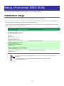
Setup of Universal RAID Utility .................................................................................. 14
Installation image ...................................................................................................................... 14
Installation and Uninstallation ..................................................................................................... 15
Preparing installation (Windows) ............................................................................................................... 16
Installation (Windows).............................................................................................................................. 17
Update Installation (Windows) .................................................................................................................. 19
Uninstallation (Windows) .......................................................................................................................... 19
Preparing installation (Linux) .................................................................................................................... 21
Installation (Linux, VMware ESX)............................................................................................................... 22
Update Installation (Linux, VMware ESX) ................................................................................................... 23
Uninstallation (Linux, VMware ESX) ........................................................................................................... 23
Starting or Stopping Universal RAID Utility ............................................................... 24
raidsrv service ........................................................................................................................... 24
Starting Universal RAID Utility in Single User Mode .................................................................................... 24
raidsrv Agent Service ................................................................................................................. 24
RAID Viewer .............................................................................................................................. 25
Log Viewer ................................................................................................................................ 26
raidcmd .................................................................................................................................... 27
Standard and Advanced Modes ................................................................................................... 28
RAID System Management Mode when startup RAID Viewer and raidcmd ................................................... 29
Changing RAID System Management Mode ............................................................................................... 29
Functions of RAID Viewer .......................................................................................... 30
Structure of RAID Viewer............................................................................................................ 30
Tree View .................................................................................................................................. 30
Computer ................................................................................................................................................ 31
4
RAID Controller ........................................................................................................................................ 31
Battery .................................................................................................................................................... 31
Disk Array ................................................................................................................................................ 31
Logical Drive ............................................................................................................................................ 32
Physical Device ........................................................................................................................................ 32
Shortcut Menu ......................................................................................................................................... 32
Operation View .......................................................................................................................... 33
Menu Bar .................................................................................................................................. 34
[File] menu .............................................................................................................................................. 34
[Control] menu ........................................................................................................................................ 34
[Tool] menu ............................................................................................................................................. 35
[Help] menu ............................................................................................................................................ 36
Status Bar ................................................................................................................................. 36
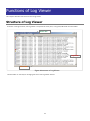
Functions of Log Viewer ............................................................................................. 37
Structure of Log Viewer .............................................................................................................. 37
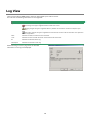
Log View ................................................................................................................................... 38
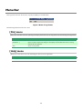
Menu Bar .................................................................................................................................. 39
[File] menu .............................................................................................................................................. 39
[Help] menu ............................................................................................................................................ 39
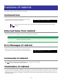
Functions of raidcmd .................................................................................................. 40
Command Line .......................................................................................................................... 40
Returned Value from raidcmd ...................................................................................................... 40
Error Messages of raidcmd ......................................................................................................... 40
Commands of raidcmd ............................................................................................................... 40
Termination of raidcmd............................................................................................................... 40
Referring to Information on RAID System ................................................................. 41
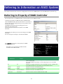
Referring to Property of RAID Controller ...................................................................................... 41
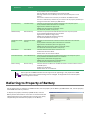
Referring to Property of Battery .................................................................................................. 42
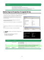
Referring to Property of Logical Drive .......................................................................................... 43
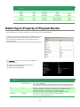
Referring to Property of Physical Device ....................................................................................... 45
Referring to Property of Disk Array .............................................................................................. 47
Checking Execution Status of Operation ....................................................................................... 47
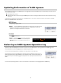
Updating Information of RAID System ......................................................................................... 48
Referring to RAID System Operation Log ..................................................................................... 48
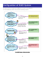
Configuration of RAID System ................................................................................... 49
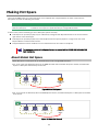
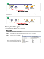
Making Hot Spare ...................................................................................................................... 50
About Global Hot Spare ............................................................................................................................ 50
About Dedicated Hot Spare ....................................................................................................................... 51
Making Global Hot Spare .......................................................................................................................... 52
Making Dedicated Hot Spare ..................................................................................................................... 53
Removing Hot Spare................................................................................................................................. 54
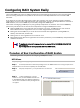
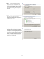
Configuring RAID System Easily .................................................................................................. 55
Procedure of Easy Configuration of RAID System ....................................................................................... 55
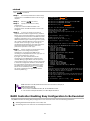
RAID Controller Enabling Easy Configuration to Be Executed ...................................................................... 57
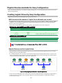
Physical Devices Available for Easy Configuration ....................................................................................... 58
Creating Logical Drives by Easy Configuration ............................................................................................ 58
Making Hot Spares by Easy Configuration .................................................................................................. 60
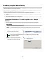
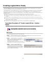
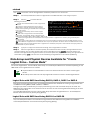
Creating Logical Drive Easily ....................................................................................................... 62
Operation Procedure of "Create Logical Drive - Simple Mode" ..................................................................... 62
Physical Devices Available for "Create Logical Drive - Simple Mode"............................................................. 64
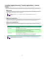
Creating Logical Drives by "Create Logical Drive - Simple Mode" ................................................................. 64
Creating Logical Drive Freely ....................................................................................................... 65
5
Operation Procedure of "Create Logical Drive - Custom Mode" .................................................................... 65
Disk Arrays and Physical Devices Available for "Create Logical Drive - Custom Mode" ................................... 68
Creating Logical Drives by "Create Logical Drive - Custom Mode" ................................................................ 69
Deleting Logical Drive................................................................................................................. 70
Deleting Logical Drive ............................................................................................................................... 70
Maintenance of RAID System ..................................................................................... 71
Providing Patrol Read for Physical Devices.................................................................................... 71
Setting Whether Patrol Read Is Executed or Not ......................................................................................... 71
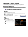
Checking Result of Executing Patrol Read .................................................................................................. 72
Setting Patrol Read Priority ....................................................................................................................... 72
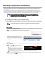
Checking Logical Drive Consistency ............................................................................................. 73
Executing Consistency Check Manually ...................................................................................................... 73
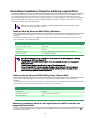
Executing Consistency Check for arbitrary Logical Drive .............................................................................. 74
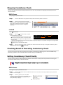
Stopping Consistency Check ..................................................................................................................... 75
Checking Result of Executing Consistency Check ........................................................................................ 75
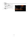
Setting Consistency Check Priority ............................................................................................................. 75
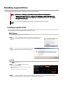
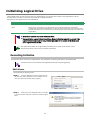
Initializing Logical Drive .............................................................................................................. 77
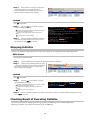
Executing Initialize ................................................................................................................................... 77
Stopping Initialize .................................................................................................................................... 78
Checking Result of Executing Initialize ....................................................................................................... 78
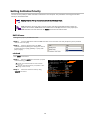
Setting Initialize Priority ............................................................................................................................ 79
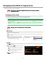
Changing Cache Mode of Logical Drive ........................................................................................ 80
Changing cache mode .............................................................................................................................. 80
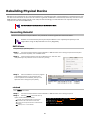
Rebuilding Physical Device .......................................................................................................... 81
Executing Rebuild..................................................................................................................................... 81
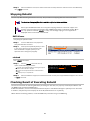
Stopping Rebuild ...................................................................................................................................... 82
Checking Result of Executing Rebuild ........................................................................................................ 82
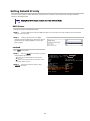
Setting Rebuild Priority ............................................................................................................................. 83
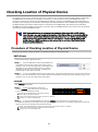
Checking Location of Physical Device ........................................................................................... 84
Procedure of Checking Location of Physical Device ..................................................................................... 84
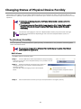
Changing Status of Physical Device Forcibly ................................................................................. 85
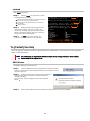
To [Online] Forcibly .................................................................................................................................. 85
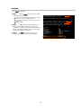
To [Failed] Forcibly ................................................................................................................................... 86
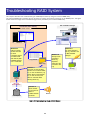
Troubleshooting RAID System ................................................................................... 88
Failure Detection Measures ......................................................................................................... 89
Status Display by RAID Viewer .................................................................................................................. 89
Status Display by raidcmd ......................................................................................................................... 89
Logging Events to RAID Log ..................................................................................................................... 89
Buzzer in RAID Controller ......................................................................................................................... 89
Logging Events to OS Log ......................................................................................................................... 90
Sending Alert to NEC ESMPRO Manager..................................................................................................... 90
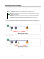
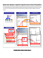
Monitoring Faults of Physical Devices ........................................................................................... 91
Operation
Operation
Operation
Operation
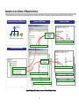
in no failures of Physical Devices ............................................................................................... 92
when redundancy of Logical Drive degraded or lost due to failure of Physical Device .................... 93
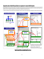
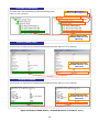
when failed Physical Device is replaced to recover RAID System .................................................. 94
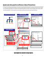
when the Logical Drive is offline due to failure of Physical Device ................................................ 95
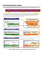
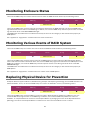
Monitoring Battery Status ........................................................................................................... 96
Monitoring Enclosure Status ........................................................................................................ 97
Monitoring Various Events of RAID System ................................................................................... 97
Replacing Physical Device for Prevention ...................................................................................... 97
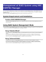
Management of RAID System using NEC ESMPRO Manager ..................................... 99
System Requirement and Installation ........................................................................................... 99
Version of NEC ESMPRO Manager.............................................................................................................. 99
Using RAID System Management Mode ....................................................................................... 99
Using "Standard Mode"............................................................................................................................. 99
6
Using "Advanced Mode" ............................................................................................................................ 99
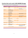
Function that can be used in NEC ESMPRO Manager ....................................................................100
Changing of Settings of Universal RAID Utility ........................................................ 101
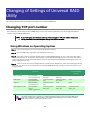
Changing TCP port number ........................................................................................................101
Using Windows as Operating System ....................................................................................................... 101
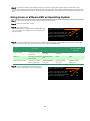
Using Linux or VMware ESX as Operating System ..................................................................................... 102
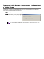
Changing RAID System Management Mode at Start of RAID Viewer ..............................................103
Notes on Use of Universal RAID Utility .................................................................... 104
Operation Environment..............................................................................................................104
Use of IPv6 ............................................................................................................................................ 104
Support for Solid State Drive (SSD) ......................................................................................................... 104
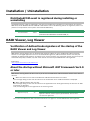
Installation / Uninstallation ........................................................................................................105
DistributedCOM event is registered during installing or uninstalling ........................................................... 105
RAID Viewer, Log Viewer ...........................................................................................................105
Verification of Authenticode signature at the startup of the RAID Viewer and Log Viewer ........................... 105
About the startup without Microsoft .NET Framework Ver2.0 or later ......................................................... 105
About the start when Runtime component of Microsoft Visual C++ 2005 SP1 library does not exist ............ 106
NEC ESMPRO Manager ..............................................................................................................106
Simultaneous operation from two or more NEC ESMPRO Manager ............................................................. 106
7
Overview
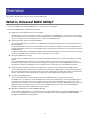
This chapter describes the overview of the Universal RAID Utility.
What is Universal RAID Utility?
The Universal RAID Utility enables RAID Systems in a computer to be managed.
The Universal RAID Utility is characterized as follows.
1. Allowing a variety of RAID Systems to be managed
Conventionally, a specific management utility must be used for each RAID System. On the other hand, only the
Universal RAID Utility can manage more than one RAID System. For the RAID Systems which the Universal RAID
Utility can manage, see the documentation on computers and RAID Systems.
2. Operating in either Standard or Advanced Mode
The Universal RAID Utility can operate in two RAID System Management Modes, which are Standard Mode and
Advanced Modes.
The Standard Mode provides the Universal RAID Utility with standard management functions of RAID Systems.
The Advanced Mode provides the Universal RAID Utility with advanced management and maintenance functions
of RAID Systems.
Using the two RAID System Management Modes appropriately depending on users and jobs allows the usability
of the Universal RAID Utility to be improved and malfunctions to be avoided.
3. Configuring RAID Systems easily
Using the Universal RAID Utility, you can configure a RAID System easily without expert knowledge of the RAID
System.
The Universal RAID Utility provides the "simple Logical Drive create function" allowing a Logical Drive to be
created by selecting only two selection items according to the guide of the Universal RAID Utility and the "Easy
Configuration" allowing a RAID System to be configured only by defining uses of unused Physical Devices.
4. Supporting general functions required for configurations, operations and maintenances of RAID Systems
The Universal RAID Utility supports general functions for configuring a RAID System (including creating Logical
Drive and making Hot Spare), general operation functions (including log recording, Patrol Read and Consistency
Check), and general functions required for maintenance (including Rebuild and Locate functions).
5. Troubleshooting RAID Systems
The Universal RAID Utility can detect failures occurred in RAID Systems by using various functions.
The RAID Viewer, the GUI of the Universal RAID Utility, indicates the configurations and status of RAID Systems
comprehensibly with trees and icons. The raidcmd, the CLI of the Universal RAID Utility, indicates the same
information too. In addition, the Universal RAID Utility registers failures occurred in RAID Systems not only to the
dedicated log but also the OS log. Further, the Universal RAID Utility can send alerts to the NEC ESMPRO
Manager normally attached to NEC Express series systems.
6. RAID System Management by NEC ESMPRO Manager
Universal RAID Utility (Windows / Linux Edition) can manage the RAID System using NEC ESMPRO Manager Ver.
5.3 or later. The RAID System that exists in a remote environment can be managed by using NEC ESMPRO
Manager like RAID Viewer and Log Viewer.
8
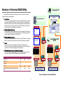
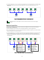
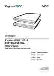
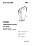
Structure of Universal RAID Utility
Management PC
The Universal RAID Utility consists of the following modules:. The module that can be used is
different depending on operating system.
Windows Server
raidsrv service
The raidsrv service always operates in the computer to manage RAID Systems. Receiving a
processing request from the RAID Viewer or raidcmd, the raidsrv service provides proper
information on a RAID System or performs an appropriate operation for the RAID System. In
addition, the raidsrv service manages events occurred in RAID Systems, notifies the RAID
Viewer of the events and/or registers them to several logs.
NEC ESMPRO Manager
Ver. 5.3
RAID Viewer
RAID Viewer (Windows Edition only)
The RAID Viewer is the Windows application managing and monitoring the RAID System by
GUI. The RAID Viewer displays the configuration and status of a RAID System graphically or
provides configuration and operation for a RAID System.
Log Viewer
Log Viewer (Windows Edition only)
The Log Viewer is the Windows application viewing the event of RAID System. The Log Viewer
allows you to see the RAID Log in which events occurred in RAID Systems are registered.
raidsrv
Agent
raidcmd
The raidcmd is the application managing and monitoring the RAID System by CLI.
The raidcmd is the command that indicates the configuration and status of a RAID System
or operates on a console providing configurations and operations.
Linux/VMware ESX
Server
raidcmd
raidcmd
raidsrv
Agent
NEC ESMPRO Manager Communication Module / raidsrv Agent
When the RAID System is managed in NEC ESMPRO Manager, raidsrv Agent controls the
communication between NEC ESMPRO Manager and Universal RAID Utility.
Operating System
Windows
Linux
VMware ESX
raidsrv service
RAID Viewer
Log Viewer
raidcmd
NEC ESMPRO Manager Communication Module (raidsrv
Agent)
RAID System
raidsrv
service
Universal RAID Utility
(Windows Version)
RAID System
Universal RAID Utility
(Linux/VMware ESX Version)
Figure 1 Configuration of Universal RAID Utility
9
raidsrv
service
Functional differences from previous version of
Universal RAID Utility
Ver2.31 and Ver2.4
The following features have been enhanced and changed from Universal RAID Utility Ver2.31
1. Support of RAID System management on the Linux or VMware ESX server by NEC ESMPRO Manager Ver.
5.3 or later.
Universal RAID Utility Linux Edition and VMware ESX Edition can manage RAID system using NEC ESMPRO
Manager Ver. 5.3 or later of the remote environment.
2. Change of the version of NEC ESMPRO Manager which supports the function of RAID System
management
Universal RAID Utility Ver2.31 supports NEC ESMPRO Manager Ver. 4.0 or later. Universal RAID Utility
Ver2.4 supports NEC ESMPRO Manager Ver. 5.3 or later.
End of Support (EOS) of NEC NEMPRO Agent ESMDiskArray
End of Support (EOS) of NEC ESM Agent ESMDiskArray, because changing of version of NEC ESMPRO
Manager which supports.
3. Addition of the following OS to support
Red Hat Enterprise Linux 6.0
Red Hat Enterprise Linux 5.6
Red Hat Enterprise Linux 4.9
SUSE Linux Enterprise Server 11 SP1
4. Addition of the hardware to support
Hard Disk Drive of capacity larger than 2TB
5. Operation
Support of fault monitoring of Hot Spare
When Hot Spare is Failed, Universal RAID Utility notifies several logs of the event "Physical Device is
Failed."
6. Display of information
Change of term of running mode
The term "running mode" in Universal RAID Utility has been changed to "RAID System Management
Mode".
Enhancement of Make Online / Make Offline
When you execute Make Online / Make Offline, Universal RAID Utility displays a warning message in
order not to corrupt the system by mistake.
10
System requirements
This chapter describes system requirements of the Universal RAID Utility.
Hardware
Computers
The computers can contain RAID Systems to be managed by the Universal RAID Utility.
RAID Systems to be managed by Universal RAID Utility
For RAID Systems which can be managed by the Universal RAID Utility, see the documentation attached to the
computer in which RAID Systems are installed and that attached to the RAID Controller including the Universal
RAID Utility.
Software (Windows)
Operating systems
The Universal RAID Utility can operate in the following operating systems.
It can operate in either 32-bit or 64-bit environment for any operating system.
Windows Server 2008 R2
Windows Server 2008
Windows Server 2003 R2 SP1 or later
Windows Server 2003 SP1 or later
Windows 7
Windows Vista
Windows XP Professional SP2 or later
Windows XP Professional x64 Edition SP1 or later
If you use "Server Core Install Option" of Windows Server 2008 or Windows Server 2008 R2,
you can use raidcmd for the management of the RAID System only (You can not use RAID
Viewer and Log Viewer).
Microsoft .NET Framework
To use the RAID Viewer and Log Viewer, Microsoft .NET Framework Version 2.0 or higher is required.
Windows Server 2008 and Windows Server 2008 R2, Windows Vista, Windows 7 include .NET Framework
Version 2.0 or higher. Therefore, you do not need to install .NET Framework in case of using them.
For the installation of Microsoft .NET Framework Version 2.0 or higher, see "Preparing installation (Windows)".
11
Runtime component of Microsoft Visual C++ 2005 SP1
library
To use the RAID Viewer, the runtime component of the Microsoft Visual C++ 2005 SP1 library is required.
Windows Server 2008 R2 and Windows 7 include the runtime component of the Microsoft Visual C++ 2005 SP1
library. Therefore, you do not need to install the runtime component of the Microsoft Visual C++ 2005 SP1 library
in case of using them as operating system.
For the installation of the runtime component of the Microsoft Visual C++ 2005 SP1 library, see "Preparing
installation (Windows)".
Software (Linux)
Operating systems
The Universal RAID Utility can operate in the following operating systems.
It can operate in either 32-bit or 64-bit environment for any operating system.
Red Hat Enterprise Linux 4.8 or later
Red Hat Enterprise Linux 5.4 or later
Red Hat Enterprise Linux 6.0
MIRACLE LINUX V4.0 SP 2 or later
Asianux Server 3
SUSE Linux Enterprise Server 10 SP 3 or later
SUSE Linux Enterprise Server 11 SP 1 or later
Software (VMware ESX)
VMware ESX
The Universal RAID Utility can operate in the following VMware ESX.
VMware ESX 4.0 Update1 or later
VMware ESX 4.1
You must install the Universal RAID Utility in the service console. Do not install in the virtual machine.
12
Others
Resources
Resource
Available Hard Disk Space
Windows
Linux/VMware ESX
250MB or more
←
(not include Microsoft .NET Framework (not include the required packages as
Ver2.0, the runtime of Microsoft Visual C++ standard C++ library...etc)
2005 SP1 library)
RAM
512MB or more
←
TCP ports used by Universal RAID Utility
The Universal RAID Utility uses the following three TCP ports.
TCP port
Description
52805
Data port
52806
Event port
52807
Communication port with NEC ESMPRO Manager
For the change of TCP port number using Universal RAID Utility, see "Changing TCP port number".
Safe Mode and Single User Mode
The Universal RAID Utility uses the network function. Accordingly, the Universal RAID Utility is unavailable in any
of the following safe modes in which the network function cannot operate.
Safe Mode
Safe Mode with Command Prompt
Safe Mode with Networking
Also, it cannot be used in the single user mode of Linux and VMware ESX. See "Starting Universal RAID Utility in
Single User Mode" about how to use the Universal RAID Utility in the single user mode.
13
Setup of Universal RAID Utility
This chapter describes installation and uninstallation of the Universal RAID Utility.
Installation image
Use the setup program of Universal RAID Utility for the installation and the uninstallation.
The setup program is contained in the installation image of the Universal RAID Utility. Before the Universal RAID Utility
can be installed or uninstalled, you must prepare the installation image.
The installation images of Universal RAID Utility are different by operating system. You need to use correct installation
image corresponding to the operating system.
Operating system
Installation image
Windows Server 2008 R2
Windows Server 2008
Windows Server 2003 R2 SP1 or later
Windows Server 2003 SP1 or later
Windows 7
Windows Vista
Windows XP SP2 or later
Windows XP x64 SP1 or later
Universal RAID Utility (Windows Edition)
Red Hat Enterprise Linux 4.8 or later
Red Hat Enterprise Linux 5.4 or later
Red Hat Enterprise Linux 6.0
MIRACLE LINUX V4.0 SP2 or later
Asianux Server 3
SUSE Linux Enterprise Server 10 SP3 or later
SUSE Linux Enterprise Server 11 SP1 or later
Universal RAID Utility (Linux Edition)
VMware ESX 4.0 Update1 or later
VMware ESX 4.1
Universal RAID Utility (VMware ESX Edition)
The installation images of Universal RAID Utility are attached to the computer or the RAID
Controller.
The latest version of Universal RAID Utility is released on the “NEC Global Site”
(http://www.nec.com/).
14
Installation and Uninstallation
This section describes the procedure of installation and uninstallation of Universal RAID Utility.
kind
Description
Installation
Install Universal RAID Utility newly, when there is not Universal RAID Utility in the computer.
Procedure (Windows)
1. Preparing installation (Windows)
2. Installation (Windows)
Procedure (Linux)
1. Preparing installation (Linux)
2. Installation (Linux, VMware ESX)
Procedure (VMware ESX)
Update Installation
1. Installation (Linux, VMware ESX)
Install the new version of Universal RAID Utility, when there is the previous version of Universal
RAID Utility in the computer
Procedure (Windows)
1. Update Installation (Windows)
Procedure (Linux, VMware ESX)
Uninstallation
1. Update Installation (Linux, VMware ESX)
Uninstall Universal RAID Utility from the computer.
Procedure (Windows)
1. Uninstallation (Windows)
Procedure (Linux, VMware ESX)
1.
Uninstallation (Linux, VMware ESX)
A user having the administrator authority should install or uninstall the Universal RAID
Utility in the computer. Only users having the administrator authority can execute the setup
program.
If you use "Server Core Install Option" of Windows Server 2008 or Windows Server 2008
R2, there is not [Start] menu. You must run setup.exe on the [Administrator : Command
Prompt].
If you use VMware ESX, press Alt key and F1 key at boot screen of VMware ESX to switch to
service console. Log in to VMware ESX with administrator authority to install or uninstall
Universal RAID Utility.
Be sure to exit RAID Viewer, Log Viewer, raidcmd, and Event Viewer before uninstalling
Universal RAID Utility.
The RAID log is not deleted at the uninstallation of Universal RAID Utility. You can refer the log
files even after uninstalling Universal RAID Utility.
15
Preparing installation (Windows)
RAID Viewer and Log Viewer use Microsoft .NET Framework Version 2.0 or higher and the runtime component of
the Microsoft Visual C++ 2005 SP1 library. Install these components if it does not exist in the computer where
the Universal RAID Utility is to be installed.
Installation of Microsoft .NET Framework
Windows Server 2008 and Windows Server 2008 R2, Windows Vista, Windows 7
include .NET Framework Version 2.0 or higher. Therefore, you do not need to install .NET
Framework in case of using them as operating system.
Please be sure to install Microsoft .NET Framework Version between 2.0 and 3.5 for proper
operation of Universal RAID Utility. Universal RAID Utility does not work properly only with
Microsoft .NET Framework Version 4.0.
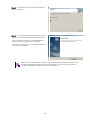
Step 1
Click [Start] - [Control Panel]. Then
double-click [Add or Remove Program].
Step 2
Click [Change or Remove Program] to list
[Currently installed programs]. If the following
programs exist in the list of [Currently installed
programs], Microsoft .NET Framework may not be
installed. If the following packages do not exist,
install the package(s).
- [Microsoft .NET Framework 2.0] (for x64, [Microsoft .NET Framework 2.0 (x64)])
Step 3
Microsoft .NET Framework Version 2.0 uses different packages depending on the CPU architecture. See the
table below to download and install the required packages.
CPU architecture
x86
Required components and their vendors
[Microsoft .NET Framework Version 2.0 Redistributable Package (x86)]
http://www.microsoft.com/downloads/details.aspx?FamilyID=0856EACB-4362-4B0D-8EDD
-AAB15C5E04F5&displaylang=en
x64
[Microsoft .NET Framework Version 2.0 Redistributable Package (x64)]
http://www.microsoft.com/downloads/details.aspx?familyid=92e0e1ce-8693-4480-84fa-7d
85eef59016&displaylang=en
Installation of the runtime component of the Microsoft Visual C++ 2005 SP1
library
Windows Server 2008 R2 and Windows 7 include the runtime component of the Microsoft
Visual C++ 2005 SP1 library. Therefore, you do not need to install the runtime component of
the Microsoft Visual C++ 2005 SP1 library in case of using them as operating system.
Step 1
Click [Start] - [Control Panel]. Then
double-click [Add or Remove Program].
Step 2
Click [Change or Remove Programs] to
list [Currently installed programs]. If the following
program exists in the list of [Currently installed
programs], the runtime component of the Microsoft
Visual C++ 2005 SP1 library may not be installed.
If not, install it.
- [Microsoft Visual C++ 2005 Redistributable]
Step 3
For the runtime component of the Microsoft Visual C++ 2005 SP1 library, see the table below to download
and install required packages.
16
CPU architecture
x86/x64
Required component and its vendor
[Microsoft Visual C++ 2005 Service Pack 1 Redistributable Package ATL Security Update]
http://www.microsoft.com/downloads/details.aspx?familyid=766a6af7-ec73-40ff-b072-911
2bab119c2&displaylang=en
Use the vcredist_x86.exe whatever the CPU architecture may be.
When you use RAID Viewer of Universal RAID Utility Ver2.3 or later, you need to install
runtime component of the Microsoft Visual C++ 2005 SP1 library that ATL Security Update
has already been applied. Install the runtime component of the Microsoft Visual C++ 2005
SP1 library to which ATL Security Update has been applied and then install Universal RAID
Utility.
Installation (Windows)
The Setup Program installs Universal RAID Utility when there is no Universal RAID Utility in the computer.
Step 1 Click [Start], [Run…], [Browse...]. Click setup.exe in the folder contained the installation image of Universal RAID
Utility and click [Open] in the [Browse] dialog box. Recognize that displays "setup.exe" in [Name] box on [Run] dialog box and
click [OK].
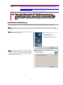
Step 2 The installation starts the InstallShield Wizard of the
Universal RAID Utility. Click [Next].
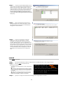
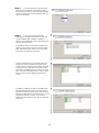
Step 3 The Universal RAID Utility is installed in \Program
Files\Universal RAID Utility (or Program Files (x86) for x64)
in the drive where the OS is started by default. To change
the installation folder, click [Change] and enter another
installation folder. Click [Next].
17
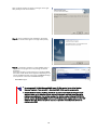
Next, the wizard appears as shown in the figure to the right.
Click [Install] to start the installation.
Step 4 At the completion of the installation, the wizard
appears as shown in the figure to the right. Click [Finish].
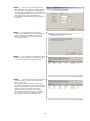
Step 5 If installation completes, "Universal RAID Utility" is
registered to the program list in the [Change or Remove
Programs].
Also, either program or both programs to manage the RAID
Controllers shown below will be registered depending on the
type of the RAID Controller, the version of ESMPRO Manager,
or the presence or absence of ESMPRO Manager.
-
WebPAMPRO Agent
Do not uninstall “LSI SAS Storage SNMP Agent X” (X is version) in the list of [Add or
Remove Program]. If you uninstall it, Universal RAID Utility cannot use normally.
Please check the setting of [When maximum log size is reached] in the [Properties] of
[System] event log. In case that [When maximum log size is reached] is not [Overwrite
events as needed], when the log size reaches the maximum size, Universal RAID Utility
cannot register the detected RAID event to the Windows Event Log and alert it to the NEC
ESMPRO Manager. Please set [When maximum log size is reached] to the [Overwrite
events as needed].
18
If you need the addition of Universal RAID Utility, you must uninstall the previous version at
first.
In the following cases, it is necessary to perform Add Install.
Installing new RAID Controller in the computer.
Removing RAID Controller from the computer.
Installing or uninstalling NEC ESMPRO Manager which manages the computer.
When you reinstall Universal RAID Utility, the following settings are changed to the default
settings. If you have changed these settings before reinstallation, you have to confirm the
settings and change them again if required.
TCP port using Universal RAID Utility
The RAID System Management Mode of RAID Viewer and raidcmd
The scheduled task of Consistency Check in task of operating system
Update Installation (Windows)
Universal RAID Utility Ver2.3 or later does not support Update Installation. If you need Universal RAID Utility
update, you must uninstall previous version at first.
When you use RAID Viewer of Universal RAID Utility Ver2.3 or later, you need to install runtime component of the
Microsoft Visual C++ 2005 SP1 library that ATL Security Update has already been applied.
For the installation of runtime component of the Microsoft Visual C++ 205 SP1 library with ATL Security Update
applied, see “Preparing installation (Windows)”.
For the uninstallation of Universal RAID Utility, see "Uninstallation (Windows)".
When the following setting is changed, you have to change the setting again.
TCP port using Universal RAID Utility
The RAID System Management Mode of RAID Viewer and raidcmd
The scheduled task of Consistency Check in task of operating system
Uninstallation (Windows)
The Setup Program uninstalls Universal RAID Utility when there is the same version of Universal RAID Utility in the
computer.
You can start the uninstallation by using the clicking [Delete] on "Universal RAID Utility"
program in the list of [Add or Remove Program].
Step 1 See “Installation (Windows)” about the procedure of starting the setup program.
Step 2 The uninstallation starts the InstallShield Wizard of
the Universal RAID Utility. The InstallShield Wizard of the
Universal RAID Utility is started. Click [Yes] on the dialog box
shown to the right to start the uninstallation. Click [No] to
abort the setup program.
19
Step 3 Uninstallation begins. A right screen is displayed
while uninstalling it.
Step 4 At the completion of the uninstallation, the wizard
appears as shown in the figure to the right. Click [Finish].
If the uninstallation completes, "Universal RAID Utility" is
deleted from the list of [Add or Remove Program].
Also, one or several programs to control RAID Controller in
your system are deleted too.
When you run " Uninstallation " while any files to be uninstalled (deleted) have been in use,
the setup program may request to restart the computer at the end of the uninstallation
process. To complete uninstallation, restart the computer.
20
Preparing installation (Linux)
You must prepare the following packages for using the Universal RAID Utility. If the following packages do not
exist in the computer that installs Universal RAID Utility, you need to install them.
Red Hat Enterprise Linux 4.8 or later
Red Hat Enterprise Linux 5.4 or later
MIRACLE LINUX V4.0 SP 2 or later
Asianux Server 3
packages
x86
x64
standard C++ library
libstdc++
libstdc++ (i386)
GCC 3.3.4 Compatibility standard C++ library
compat-libstdc++-33
compat-libstdc++-33 (i386)
GCC library
libgcc
libgcc (i386)
cron
vixie-cron
vixie-cron (x86_64)
Red Hat Enterprise Linux 6.0
packages
x86
x64
standard C++ library
-
libstdc++ (i386)
GCC 3.3.4 Compatibility standard C++ library
compat-libstdc++-33
compat-libstdc++-33 (i386)
GCC library
-
libgcc (i386)
others
pciutils
pciutils
glibc(i386)
nss-softokn-freebl(i386)
SUSE Linux Enterprise Server 10 SP3 or later
SUSE Linux Enterprise Server 11 SP1 or later
packages
x86
x64
standard C++ library
libstdc++
libstdc++ (x86_64)
GCC 3.3.4 Compatibility standard C++ library
libstdc++33
libstdc++33-32bit (x86_64)
GCC library
libgcc
libgcc (x86_64)
cron
cron
cron (x86_64)
You can recognize the existence and install these packages by the following procedure (This procedure is
example using GCC 3.3.4 Compatibility standard C++ library).
Step 1 You can check by rpm command which does GCC
3.3.4 Compatibility standard C++ library exist in the
> rpm -q compat-libstdc++-33
1
compat-libstdc++-33-3.2.3-*
computer or not. If it has existed in your computer, rpm
>
command displays the right way (the part of "*" is
different by operating system). In this case, see
"Installation (Linux, VMware ESX)". If it has not existed in your computer, rpm command displays the right way. In this case,
install it to your computer.
21
Step 2 Log in to the computer with administrator
2
authority to install Universal RAID Utility.
Insert the install disk of operating system included the
"GCC 3.3.4 Comparability standard C++ library" to
CD-ROM/DVD-ROM drive of your computer.
Step 3 Move current directory to the directory existed
GCC 3.3.4 Compatibility standard C++ library, install it by
rpm command (the part "*" is different by operating
system).
> rpm -q compat-libstdc++-33
package compat-libstdc++-33 is not installed
> rpm -ivh compat-libstdc++-33-*.i386.rpm
Preparing...
##############################
[100%]
1:compat-libstdc++-33 ##############################
[100%]
> rpm -q compat-libstdc++-33
compat-libstdc++-33-3.2.3-*
>
3
4
Step 4 You can see the result of installation by rpm command. If the installation finishes, rpm command displays the below
compat-libstdc++-33-3.2.3-*
(the part of "*" is different by operating system)
If the installation fails, rpm command does not display this package name.
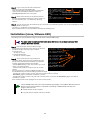
Installation (Linux, VMware ESX)
Use setup.sh in the installation image to install latest Universal RAID Utility.
You must install the Universal RAID Utility in the ESX Server. Do not install Universal RAID
Utility in the virtual machine.
Step 1 Execute setup.sh in the installation image.
Change the current directory to the directory in which the
installation image is stored and type as follows:
(In case of Linux)
sh setup.sh --install
(In case of VMware ESX)
sh setup.sh --install --reptblen
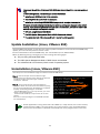
Step 2 At the end of setup.sh, the installation is
> cd directory name involved installation image
> sh setup.sh --install
>
> rpm -q UniversalRaidUtility
UniversalRaidUtility-x.yy-z
>
> rpm –q eciservice-a.bb-x.i386
eciservice-a.bb-x.i386
>
> rpm –q Lib_Utils
Lib_Utils-a.bb-cc.noarch
>
> rpm -q storelib
storelib-a.bb-0
>
> rpm -q WebPAMPRO_Agent
WebPAMPRO_Agent-3.aa.bbbb-cc
>
1
2
completed. Check the result of the installation by using
the rpm command. When the installation is completed
properly, the following packages are installed:
- UniversalRAIDUtility-x.yy-z (x is major version, yy is minor
version, z is revision number)
- eciservice-a.bb-x.i386 (a is major version, bb is minor
version)
Also, the programs to manage the RAID Controllers will
be installed with any one of the following combinations depending on the type of the RAID Controller used in your system.
- storelib-a.bb-0 (a.bb is version) and Lib_Utils-a.bb-cc.noarch (a.bb-cc is version)
- WebPAMPRO_Agent-3.aa.bbbb-cc (aa.bbbb-cc is version)
- storelib-a.bb-0 (a.bb is version), Lib_Utils-a.bb-cc.noarch (a.bb-cc is version) and WebPAMPRO_Agent-3.aa.bbbb-cc
(aa.bbbb-cc is version)
If the installation fails, these packages do not exist in the computer.
Universal RAID Utility does not install the following packages in the VMware ESX environment.
Please note that the installation is finished successfully in VMware ESX even after the
program does not exist.
storelib-a.bb-0. (a.bb is version)
Lib_Utils-a.bb-cc.noarch (a.bb-cc is version)
22
If you need the addition of Universal RAID Utility, you must uninstall the previous version at
first.
In the following cases, it is necessary to perform Add Install.
Installing new RAID Controller in the computer.
Removing RAID Controller from the computer.
Installing or uninstalling NEC ESMPRO Manager which manages the computer.
When you reinstall Universal RAID Utility, the following settings are changed to the default
settings. If you have changed these settings before reinstallation, you have to confirm the
settings and change them again if required.
TCP port using Universal RAID Utility
The RAID System Management Mode of RAID Viewer and raidcmd
The scheduled task of Consistency Check in task of operating system
Update Installation (Linux, VMware ESX)
Universal RAID Utility Ver2.3 or later does not support Update Installation. If you need Universal RAID Utility
update, you must uninstall previous version at first.
For the uninstallation of Universal RAID Utility, see "Uninstallation (Linux, VMware ESX)".
When the following setting is changed, you have to change the setting again.
TCP port using Universal RAID Utility
The RAID System Management Mode of RAID Viewer and raidcmd
The scheduled task of Consistency Check in task of operating system
Uninstallation (Linux, VMware ESX)
Use setup.sh in the installation image to uninstall Universal RAID Utility.
Step 1 Execute setup.sh in the installation image.
Change the current directory to the directory in which the
installation image is stored and type as follows:
sh setup.sh --uninstall
Step 2 At the end of setup.sh, the uninstallation is
completed. Check the result of the uninstallation by using
the rpm command. When the uninstallation is completed
properly, the following package is uninstalled:
- UniversalRaidUtility-x.yy-z (x is major version, yy is minor
version, z is revision number)
- eciservice-a.bb-x.i386 (a is major version, bb is minor
version,)
Also, one or several packages to control RAID Controller
are uninstalled too.
> cd directory name involved installation image
> sh setup.sh --uninstall
>
> rpm -q UniversalRaidUtility
package UniversalRaidUtility is not installed
>
> rpm –q eciservice
package eciservice is not installed
>
> rpm -q storelib
package storelib is not installed
>
> rpm -q WebPAMPRO_Agent
package WebPAMPRO_Agent is not installed
>
1
2
If other application is using "eciservice-a.bb-x.i386" (a is major version, bb is minor version),
"eciservice-a.bb-x.i386" (a is major version, bb is minor version) is not uninstalled. Please
note that the uninstallation is finished successfully even if the program exists in this case.
23
Starting or Stopping Universal RAID
Utility
This chapter describes the procedure of starting or stopping each module in the Universal RAID Utility.
raidsrv service
The raidsrv service is started automatically when your computer is booted and stopped automatically when your
computer is shut down.
Without operation of the raidsrv service, the Universal RAID Utility cannot operate normally. Neither makes the raidsrv
service be not started nor stop the raidsrv service.
In case that the operating system is Linux or VMware ESX, if the raidsrv service terminates
abnormally due to an error or the process of the raidsrv service is terminated forcibly, the
lock file for avoiding double starts is left. If the state remains, the raidsrv service may not be
started.
If this occurs, delete the following file before restarting the raidsrv service:
/var/lock/subsys/raidsrv
Starting Universal RAID Utility in Single User Mode
The Universal RAID Utility uses network functions. Accordingly, the Universal RAID Utility cannot be used in the
single user mode of Linux and VMware ESX without network functions. To use the Universal RAID Utility in the
single user mode, first enable the network functions in the following procedure and start the raidsrv service.
Step 1 Start the network service.
Step 2 Start the raidsrv service.
Step 3 Check that the raidsrv service is started normally.
If a process ID appears, the raidsrv service is started
normally.
> /etc/init.d/network start
>
> /etc/init.d/raidsrv start
>
> /etc/init.d/raidsrv status
raidsrv (pid 3738 3718) is running...
>
1
2
3
raidsrv Agent Service
The raidsrv Agent service is started automatically when your computer is booted and stopped automatically when your
computer is shut down.
Without operation of the raidsrv service, Universal RAID Utility cannot be communicated with NEC ESMPRO Manager
Neither make the raidsrv service be not started nor stop the raidsrv service.
In case that the operating system is Linux or VMware ESX, if the raidsrv Agent Service
terminates abnormally due to an error or the process of the raidsrv Agent Service is
terminated forcibly, the lock file for avoiding double starts is left. If the state remains, the
raidsrv Agent Service may not be started.
If this occurs, delete the following file before restarting the raidsrv Agent Service:
/var/lock/subsys/raidsrv_agent
raidsrv Agent service can not use in Single User Mode.
24
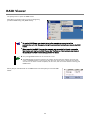
RAID Viewer
Use [Start] menu to open the RAID Viewer.
Click [Start], and point menu in order to [Programs],
[Universal RAID Utility] and [RAID Viewer].
To use the RAID Viewer, you should log on to the computer as a user having the
administrator authority. Only users having the administrator authority can execute the RAID
Viewer.
When you start the RAID Viewer on the computer not connected to internet,, may wait a
few minutes until startup the RAID Viewer. See "Verification of Authenticode signature at
the startup of the RAID Viewer and Log Viewer" for detail.
Only a single RAID Viewer can be started at a time.
The RAID Viewer cannot be started if the raidsrv service does not operate. An error may
occur if the RAID Viewer is started just after the start of the OS. It is because the raidsrv
service has not been started completely. In this case, wait for a while before restarting the
RAID Viewer.
Select [File] on the Menu Bar of the RAID Viewer and click [Exit] to close the RAID
Viewer.
25
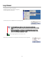
Log Viewer
Use [Start] menu to open the Log Viewer.
Click [Start], and point menu in order to [Programs],
[Universal RAID Utility], [Log Viewer].
Or select [Tool] menu of the RAID Viewer and click [Log Viewer].
To use the Log Viewer, you should log on to the computer as a user having the
administrator authority. Only users having the administrator authority can execute the Log
Viewer.
When start the Log Viewer on the computer not connected to internet, may wait a few
minutes until startup the Log Viewer. See "Verification of Authenticode signature at the
startup of the RAID Viewer and Log Viewer" for detail.
Only a single Log Viewer can be started at a time.
Select [File] on the Menu Bar of the Log Viewer and click [Exit] to close the Log Viewer.
26
raidcmd
raidcmd is command on console as "Command Prompt" in Windows and console (terminal) in Linux and VMware ESX.
The raidcmd is executed on a console. Use the raidcmd by the methods described in "Functions of raidcmd".
A user having the administrator authority should run the raidcmd. Only users having the
administrator authority can execute the raidcmd.
In case of the operating system is Linux or VMware ESX, the raidcmd can't start by existing
the lock file after aborted it. If you start the raidcmd when the lock file exists, the raidcmd
displays the following message.
raidcmd:<RU4009> The raidcmd command is already running.
Delete the lock file (/var/lock/subsys/raidcmd), if the raidcmd displays this message when
some processes of the raidcmd do not execute at same time,
In case of the operating system is Windows Server 2008 or Windows Server 2008 R2 , Windows Vista, Windows 7, you
must use "[Administrator: Command Prompt]" for running raidcmd. If you use normal Command Prompt, you cannot see
the message of raidcmd because of raidcmd runs in the another "[Administrator: Command Prompt]" . You can use
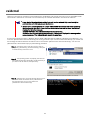
"[Administrator: Command Prompt]" by the following procedure.
Step 1 Click [Start] menu, and point menu in order to
[Programs], [Accessories], [Command Prompt], click [Run
as administrator] on shortcut menu.
Step 2 The operating system may display [User Account
Control] dialog box after clicked [Run as Administrator]. If
you want to run the raidcmd, click [Continue].
Step 3 [Administrator: Command Prompt] will start soon.
You should check the window title is "[ Administrator:
Command Prompt]". You can use raidcmd on
[Administrator: Command Prompt].
3
27
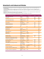
Standard and Advanced Modes
The RAID Viewer and raidcmd can operate in two RAID System Management Modes, which are Standard Mode and
Advanced Modes.
The Standard Mode provides the RAID Viewer and raidcmd with standard management functions for RAID Systems.
The Advanced Mode provides the RAID Viewer and raidcmd with advanced management and maintenance functions for
RAID Systems.
Using the two RAID System Management Modes appropriately depending on users and jobs allows the usability of the
RAID Viewer to be improved and malfunctions to be avoided.
The table below lists the functions of the RAID Viewer and raidcmd available in each mode.
Function
RAID Viewer
function
raidcmd
command
Standard
mode
Advanced
mode
Update display information
Rescan
rescan
See property
Property
property
Create Logical Drive (simple)
Create Logical Drive
(Simple)
mklds
Create Logical Drive (custom)
Create Logical Drive
(Custom)
mkldc
Silence Buzzer
Silence Buzzer
sbuzzer
Consistency Check (start)
Consistency Check
cc
Consistency Check (stop)
[Stop] on Operation
View
cc
Consistency Check (start)
for schedule running
NA
ccs
Initialize (start)
Initialize
init
Initialize (stop)
[Stop] on Operation
View
init
Delete Logical Drive
Delete Logical Drive
delld
Rebuild (start)
Rebuild
rebuild
Rebuild (stop)
[Stop] on Operation
View
rebuild
Hot Spare (make)
Make Hot Spare
hotspare
Hot Spare (remove)
Remove Hot Spare
hotspare
Change Status of Physical Device (Online)
Make Online
stspd
Change Status of Physical Device (Failed)
Make Offline
stspd
Location of Physical Device
Locate (Lamp)
slotlamp
Easy Configuration
Easy Configuration
econfig
Start Log Viewer
Log Viewer
NA
Change RAID System Management Mode
Standard Mode
Advanced Mode
runmode
See the version
About... in [Help]
menu
run raidcmd without
command
See status of operation
Operation View
oplist
Set option parameters of RAID Controller
Property of RAID
Controller
optctrl
Set option parameters of Logical Drive
Property of Logical
Drive
optld
28
RAID System Management Mode when startup RAID Viewer
and raidcmd
RAID Viewer
RAID Viewer always starts with Standard Mode. You can change the RAID System Management Mode when
RAID Viewer starts. See "Changing RAID System Management Mode at Start of RAID Viewer".
raidcmd
raidcmd starts with Standard Mode at first after installing Universal RAID Utility. If you want to change the
RAID System Management Mode, you must to use "runmode" command (The RAID System Management
Mode does not change the mode when restart the computer).
Changing RAID System Management Mode
The procedure of changing the RAID System Management Mode is below.
RAID Viewer
Use [Advanced Mode] or [Standard Mode] in [Tool] menu.
See "[Tool] menu" for detail.
raidcmd
Use "runmode" command.
Step 1
If you want to change from Standard
Mode to Advanced Mode, run "runmode" command
with -md=a parameter.
1
> raidcmd runmode -md=a
Changed RAID System Management Mode to "Advanced Mode".
>
>
> raidcmd runmode -md=s
Changed RAID System Management Mode to "Standard Mode".
>
Step 2
2
If you want to change from Advanced
Mode to Standard Mode, run "runmode" command
with -md=s parameter.
29
Functions of RAID Viewer
This chapter describes the functions of the RAID Viewer.
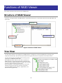
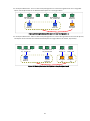
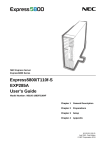
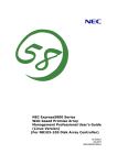
Structure of RAID Viewer
As shown in the figure below, the RAID Viewer is composed of four parts, or Tree View, Operation View, Menu Bar and
Status Bar.
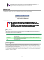
Menu Bar
Operation View
Tree View
Status Bar
Figure 2 Structure of RAID Viewer
Tree View
The Tree View indicates the configuration of RAID Systems managed by the Universal RAID Utility existing in your
computer hierarchically. The Tree View also indicates the types and status of components with relevant icons.
The Tree View displays each RAID System existing in your
computer as a RAID Controller node.
Each RAID Controller node has the node of a Battery on
RAID Controller, created all Logical Drives and Disk Array
and connected all Physical Devices. A single node includes
at least a single component of each type.
Every component is accompanied by an icon. The icons
indicate the type and the status of each component
(computer, RAID Controller, Battery, Logical Drive, and
Physical Device) graphically.
30
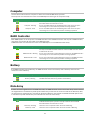
Computer
The first level node shows the computer in which the Universal RAID Utility operates.
The computer icon indicates the status of the RAID Systems existing in the computer totally.
Icon
Meaning
Description
Computer - Normal
All RAID Systems in the computer operate normally. Problems which RAID
Controllers define as failures do not occur.
Computer - Warning
One or more RAID Systems of the following status exist in the computer:
"Containing one or more failed components but being operable"
Computer - Fatal
One or more RAID Systems of the following status exist in the computer:
"Containing one or more failed components and being inoperable"
RAID Controller
Each RAID System on the computer is the RAID Controller node. A RAID Controller node equals a RAID Controller,
and shows the number, ID and model of the RAID Controller.
A RAID Controller icon indicates the status of the RAID System on the RAID Controller totally.
Icon
Meaning
Description
RAID Controller - Normal
The all of components(Battery, Logical Drive, Physical Device) operates
normally on the RAID Controller. Problems which the RAID Controller detects
as failures do not occur.
RAID Controller - Warning
One or more components of the following status exist on the RAID Controller :
"Containing one or more failed components but being operable"
RAID Controller - Fatal
One or more components of the following status exist in the RAID Controller :
"Containing one or more failed components and being inoperable"
Battery
If the RAID Controller has the Battery, the RAID Controller node has a Battery node. A Battery node and icon
shows the status of Battery.
Icon
Meaning
Description
Battery - Normal
The Battery operates normally.
Battery - Warning
The RAID Controller detects any problem of the Battery.
Disk Array
If there are some Logical Drive in the RAID Controller, the RAID Controller node has the Disk Array nodes included
the Logical Drives. The Disk Array node equals a Disk Array, and shows the number and ID of the Disk Array. Also,
the created some Logical Drives, consisted of all Physical Devices and created some Dedicated Hot Spares exist
in the Disk Array node. A Disk Array icon indicates the status of these totally.
Icon
Meaning
Description
Disk Array - Normal
The created all Logical Drives, consisted of all Physical Devices and created
all Dedicated Hot Spares operates normally. Problems which the RAID
Controller detects as failures do not occur.
Disk Array - Warning
These are some components which the status is Warning.
Disk Array - Fatal
These are some components which the status is Fatal or Warning.
31
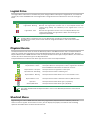
Logical Drive
The Logical Drive node exists in the Disk Array node. A Logical Drive node equals a Logical Drive, and shows the
number, ID, status and RAID Level of the Logical Drive. A Logical Drive icon indicates the status of the Logical
Drive.
Icon
Meaning
Description
Logical Drive - Normal
The Logical Drive operates normally.
Logical Drive - Warning
Because the Logical Drive contains one or more Physical Devices with
[Status] being [Failed], the redundancy of the Logical Drive is lost or
degraded.
Logical Drive - Fatal
Because the Logical Drive contains one or more Physical Devices with
[Status] being [Failed], the Logical Drive is offline and accessing to the
Logical Drive is disabled.
A Logical Drive is created by two or more Disk Arrays according to the kind of the RAID
Controller. In this case, there are the nodes of a Logical Drive exist in two of more the nodes
of Disk Arrays.
Physical Device
The Physical Device node exists in either the Disk Array node or the RAID Controller node. The Physical Device
which has created the Logical Drive and created Dedicated Hot Spare exists in the Disk Array node. The other
Physical Device exists in RAID Controller node. The Physical Device node equals a Physical Device, and shows the
number, ID, status and device type of the Physical Device.
A Physical Device icon indicates the device type and the status of the Physical Device.
Icon
Meaning
Description
Physical Device - Ready
The Physical Device is not used to create a Logical Drive yet.
Physical Device - Online
The Physical Device is already used to create a Logical Drive. Problems
which the RAID Controller detects as failures do not occur.
Physical Device - Hot Spare
The Physical Device is registered as a Hot Spare.
Physical Device - Rebuilding
The Physical Device which is rebuilding now.
Physical Device - Warning
The Physical Device which detects one or more S.M.A.R.T. errors.
Physical Device - Fatal
The Physical Device which is detected a failure by RAID Controller.
Tape Drive
CD Drive/DVD Drive
The Physical Device which device type is [Tape Drive].
The Physical Device which device type is [CD/DVD].
The nodes of Dedicated Hot Spare created to two or more Disk Arrays existed in each node of
Disk Array.
Shortcut Menu
Right-clicking the node of RAID Controller, Disk Array, Logical Drive, Physical Device and Battery allows the
shortcut menu to appear. On the shortcut menu, you can display the property and execute the something
operation. See "Menu Bar" for detail of each function.
32
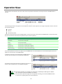
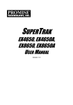
Operation View
The Operation View indicates the status and results of operations executed in the computer after the RAID Viewer is
started.
Figure 3 Operation View
The following operations may appear on the Operation View. For each operation, the target component and the status of
the operation appear.
Initialize
Rebuild
Consistency Check
Operations being executed while the RAID Viewer is started and those started after the RAID Viewer is started are listed.
You can see the status and result of operations by the value of [Status].
Status
Description
Running (N %)
The operation is running (N is progress).
Completed
The operation completed.
Failed
The operation failed.
Stopped
The operation stopped (by [Stop]).
Paused (N %)
The operation is paused (N is progress).
Queued (N %)
The operation is queued (N is progress).
Stop Processing
The operation is being stopped (by [Stop]).
Terminated operations continue to appear until the RAID Viewer is closed. However, the terminated operations will not
appear at the next start of the RAID Viewer.
To delete an operation terminated while the RAID Viewer is
started, click the operation to be deleted and [Delete].
An operation being executed can be stopped on the way. To
do this, click the operation to be stopped and [Stop].
Operations allowed to be stopped vary depending on RAID System Management Modes.
See "Standard and Advanced Modes" for details.
The stop of the operation might not be supported according to the kind of RAID Controller.
In that case, the [Stop] does not become effective.
33
When progress is frequently updated such as initializing a Logical Drive with extremely small
capacity, the progress of [Status] might not be able to be displayed correctly. Correct
progress is displayed when [Rescan] in [File] menu is run at such time.
Menu Bar
The RAID Viewer has four menu items on the Menu Bar, or [File], [Control], [Tool] and [Help].
Figure 4 Menu of RAID Viewer
The following describes the menu items.
With the RAID System Management Mode of the RAID Viewer being "Standard", the
functions unavailable in the Standard Mode do not appear on the pull-down menus of the
menu items.
Depending on the type or status of the target component selected on the Tree View, some
menu items cannot be executed. If so, clicking such a menu item is disabled.
[File] menu
[File] menu includes items for updating the display information on the RAID Viewer, displaying the property of
each component, and terminating the RAID Viewer.
Menu item
Description
[Rescan]
The Universal RAID Utility acquires the configuration and state information from all of RAID
System again, and updates the management information by them. The RAID Viewer displays the
newest information.
[Properties...]
Indicates the property of the component selected on the Tree View (RAID Controller, Battery,
Disk Array, Logical Drive or Physical Device).
[Exit]
Closes the RAID Viewer.
[Control] menu
[Control] menu includes items for operating RAID Controllers, Logical Drives, and Physical Devices. To use a
function subordinate to [Control] menu, first click the target component on the Tree View and select the menu
item to be executed from the pull-down menu.
Some functions of [Control] menu may be disabled depending on the type or status of the selected component.
If the RAID System Management Mode of the RAID Viewer is set to the Standard Mode, the functions restricted in
the Standard Mode are disabled. See "Standard and Advanced Modes" for the functions available depending on
RAID System Management Modes.
34
Functions executable by RAID Controller
Menu item
Description
[Create Logical Drive]
Creates a Logical Drive in the selected RAID Controller.
[Create Logical Drive] has two modes, [Simple] and [Custom].
In the [Simple] mode, a Logical Drive can be simply created only by selecting a RAID
Level and Physical Devices.
In the [Custom] mode, a Logical Drive can be created by specifying detailed settings.
[Silence Buzzer]
Stops the Buzzer in the RAID Controller.
Functions executable for Logical Drive
Menu item
Description
[Consistency Check]
Executes Consistency Check for the selected Logical Drive.
[Initialize]
Initializes the selected Logical Drive.
[Initialize] has two modes, [Full] and [Quick].
In the [Full] mode, initializes the entire area of a Logical Drive.
In the [Quick] mode, initializes only several leading blocks including the information on
managing a Logical Drive.
[Delete Logical Drive]
Deletes the selected Logical Drive.
Functions executable for Physical Device
Menu item
Description
[Rebuild]
Rebuilds the selected Physical Device.
[Hot Spare]
Makes a Hot Spare with the selected Physical Device or removes a Hot Spare.
[Make Global Hot Spare] makes Physical Devices be Global Hot Spares available as Hot
Spares of all Logical Drives in the relevant RAID System.
[Make Dedicated Hot Spare...] makes Physical Devices be Dedicated Hot Spares
available as Hot Spares of specific Logical Drives.
[Remove Hot Spare] removes Physical Devices from Hot Spares.
[Make Online]
Sets the selected Physical Device to online.
[Make Offline]
Sets the selected Physical Device to offline.
[Locate(Lamp)]
Goes on (or blinks) the lamp on the slot where the selected Physical Device is installed.
[ON] goes on (or blinks) the lamp.
[OFF] goes off the lamp.
[Tool] menu
[Tool] menu includes tools used to manage RAID Systems and items for changing the operation of the RAID
Viewer.
Menu item
Description
[Easy Configuration...]
Executes Easy Configuration allowing a RAID System to be configured easily.
[Log Viewer]
Starts the Log Viewer.
[Advanced Mode] or
[Standard Mode]
Alters the RAID System Management Mode. The item varies depending on the RAID System
Management Mode.
[Advanced Mode] sets the RAID System Management Mode to the Advanced Mode.
[Standard Mode] sets the RAID System Management Mode to the Standard Mode.
[Option...]
Allows you to provide settings for the Universal RAID Utility.
35
[Help] menu
[Help] menu includes the item of indicating the version and revision of the Universal RAID Utility and the version
of the RAID Viewer.
Menu item
[About...]
Description
Indicates the version and revision of the Universal RAID Utility and the version of the RAID
Viewer.
Status Bar
The Status Bar indicates the current RAID System Management Mode of the RAID Viewer.
Figure 5 Status Bar of RAID Viewer
36
Functions of Log Viewer
This chapter describes the functions of the Log Viewer.
Structure of Log Viewer
As shown in the figure below, the Log Viewer is composed of three parts, or Log View, Menu Bar and Status Bar.
Menu Bar
Log View
Status Bar
Figure 6 Structure of Log Viewer
The Status Bar is used only for changing the size of the Log Viewer window.
37
Log View
The Log View indicates RAID System operation logs logged by the raidsrv service.
You can view the following information on the Log View.
Item
Type
Description
Logs are classified into three types as follows:
Fatal: A log of the type is registered when a fatal error occurs.
Warning: A log of the type is registered when a problem occurs which is not fatal but requires your
attention.
Information: A log of the type is registered at occurrence of an event such as execution of an operation
without any problem.
Date
Indicates the date on which the event occurred.
Time
Indicates the time at which the event occurred in the 24-hour format.
ID
Indicates the event ID of the log.
Description
Indicates the contents of the log.
Double-clicking an arbitrary log allows the detailed
information on the log to be displayed.
38
Menu Bar
The Log Viewer has two menu items, or [File] and [Help] on the Menu Bar.
Figure 7 Menu of Log Viewer
The following describes each menu item.
[File] menu
[File] menu includes items for updating the display information on the Log Viewer and terminating the Log Viewer.
Menu item
Description
[Refresh]
Reads the contents in the RAID Log and updates the Log View to the latest.
[Properties...]
Opens the [Event Properties] dialog box and displays the detailed information on the log
selected by the Log Viewer.
[Exit]
Closes the Log Viewer.
[Help] menu
[Help] menu includes the item of indicating the version of the Log Viewer.
Menu item
[About...]
Description
Indicates the version of the Log Viewer.
39
Functions of raidcmd
This chapter describes the functions of the raidcmd.
Command Line
To use the raidcmd, specify a command and one or more
parameters for the command if necessary.
> raidcmd command <parameters of command>
Executing the raidcmd without any command and its parameters indicates the version of the
raidcmd.
Returned Value from raidcmd
The returned value of the raidcmd is the result of executing the command.
Returned value
Execution result
0
Normal termination of command
1
Abnormal termination of command
Error Messages of raidcmd
When a command of the raidcmd terminates abnormally,
the relevant error message appears in the following format:
> raidcmd (command) (parameters of command)
raidcmd : error message
>
Commands of raidcmd
See " Appendix B : raidcmd Command Reference " for commands of the raidcmd.
Use "help" command, displays the help of raidcmd.
Termination of raidcmd
In case of the operating system is Windows, raidcmd is the batch file in system folder (the batch file in system folder call
raidcmd binary in the installed folder of Universal RAID Utility). Therefore, if you terminate raidcmd by CTRL + C key, the
operating system displays the message as "Terminate batch job (Y/N)?". When displays this message, raidcmd binary is
terminated already.
40
Referring to Information on RAID System
This chapter describes how to see the configurations and status of RAID Systems and the RAID System operation log.
Referring to Property of RAID Controller
For the information on a RAID Controller, see the property of the RAID Controller.
To display the property of RAID Controller by RAID Viewer,
click the RAID Controller whose information is to be seen on
the Tree View and click [Properties] on the pull-down menu
of menu item [File].
The [RAID Controller Properties] dialog box has the
[General] and [Option] tabs.
The [General] tab indicates the property of the RAID
Controller.
The [Option] tab allows you to see the settings of the RAID
Controller.
You can change the settings in the Advanced Mode.
Use "property" command to see property of a RAID
Controller by raidcmd.
> raidcmd property -tg=rc -c=1
RAID Controller #1
ID
: 0
Vendor
: LSI Corporation
Model
: MegaRAID SAS PCI Express(TM)
ROMB
Firmware Version
: 1.12.02-0342
Cache Size
: 128MB
Battery Status
: Normal
Rebuild Priority
: High
Consistency Check Priority : Low
Patrol Read
: Enable
Patrol Read Priority
: Low
Buzzer Setting
: Enable
>
-tg : Specify "rc" to see property of a RAID Controller
-c : Number of the RAID Controller
Item
RAID Viewer
Item
raidcmd
Description
Number
RAID Controller #X
Indicates the management number (logical address) of the RAID Controller in the
Universal RAID Utility.
The Universal RAID Utility assigns a number beginning with 1 for each RAID
Controller.
ID
ID
Indicates the original identification value of the RAID Controller. The BIOS utility
of the RAID Controller uses the address of the identification value.
Vendor
Vendor
Indicates the vendor of the RAID Controller.
Model
Model
Indicates the model name of the RAID Controller.
Firmware Version
Firmware Version
Indicates the version of the RAID Controller.
Cache Size
Cache Size
Indicates the size of cache on RAID Controller in MB.
41
Item
RAID Viewer
Item
raidcmd
-
Description
Battery Status
Indicates the status of the Battery installed in the RAID Controller.
Three possible status are as follows:
Normal: Indicates that the Battery can be used normally.
Warning: Indicates that the Battery cannot be used normally due to some
reason.
Not Present: Indicates that no Battery is installed in the RAID Controller.
This item is indicated by raidcmd only. You need to see the property of Battery for
seeing the information of Battery by RAID Viewer.
Initialize Priority
Initialize Priority
Indicates the priority level of Initialize executed in the computer system.
Three possible Initialize Priorities are as follows:
High: Executes Initialize at high priority.
Middle: Executes Initialize at balanced priority.
Low: Executes Initialize at low priority.
Rebuild Priority
Rebuild Priority
Indicates the priority level of Rebuild executed in the computer system.
Three possible Rebuild Priorities are as follows:
High: Executes Rebuild at high priority.
Middle: Executes Rebuild at balanced priority.
Low: Executes Rebuild at low priority.
Consistency Check
Priority
Consistency Check
Priority
Indicates the priority level of Consistency Check executed in the computer
system.
Three possible Consistency Check Priorities are as follows:
High: Executes Consistency Check at high priority.
Middle: Executes Consistency Check at balanced priority.
Low: Executes Consistency Check at low priority.
Patrol Read
Patrol Read
Indicates whether Patrol Read is executed or not.
Enable: Executes Patrol Read.
Disable: Does not execute Patrol Read.
Patrol Read Priority
Patrol Read Priority
Indicates the priority level of Patrol Read executed in the computer system.
Three possible Patrol Read Priorities are as follows:
High: Executes Patrol Read at high priority.
Middle: Executes Patrol Read at balanced priority.
Low: Executes Patrol Read at low priority.
Buzzer Setting
Buzzer Setting
Indicates whether the Buzzer of the RAID Controller is used if a failure occurs in
the RAID System.
Enable: Uses the Buzzer.
Disable: Does not use the Buzzer.
Some types of the RAID Controller do not support items appearing in the properties of RAID
Controllers and/or items whose settings can be changed. Unsupported items indicate space
or do not appear in the list.
Referring to Property of Battery
For the information on a Battery on RAID Controller, see the property of the Battery by RAID Viewer and, see the property
of the RAID Controller by raidcmd.
To display the property of Battery by RAID Viewer, click the
Battery whose information is to be seen on the Tree View and
click [Properties] on the pull-down menu of menu item [File].
The [General] tab indicates the property of the Battery.
42
Item
RAID Viewer
Status
Description
Indicates the status of the Battery installed in the RAID Controller.
Three possible status are as follows:
Normal: Indicates that the Battery can be used normally.
Warning: Indicates that the Battery cannot be used normally due to some reason.
Not Present: Indicates that no Battery is installed in the RAID Controller.
Referring to Property of Logical Drive
For the information on a Logical Drive, see the property of the Logical Drive.
To display the property of Logical Drive by RAID Viewer, click
the Logical Drive whose information is to be seen on the
Tree View and click [Properties] on the pull-down menu of
menu item [File].
The [Logical Drive Properties] dialog box contains the
[General] and [Option] tabs.
The [General] tab indicates the property of the Logical Drive.
The [Option] tab allows you to see the settings of the Logical
Drive.
You can change the settings in the Advanced Mode.
Use "property" command to see property of a Logical Drive
by raidcmd.
-tg : Specify "ld" to see property of a Logical Drive
-c : Number of the RAID Controller
-l : Number of the Logical Drive
Item
RAID Viewer
Item
raidcmd
> raidcmd property -tg=ld -c=1 -l=1
RAID Controller #1 Logical Drive #1
ID
: 0
Physical Device Number
: 1, 2, 3
Disk Array Information
: 1 (order 1/1)
RAID Level
: RAID 5
Capacity
: 20GB
Stripe Size
: 64KB
Cache Mode (Setting)
: Auto Switch
Cache Mode (Current)
: Write Back
Status
: Online
>
Description
Number
RAID Controller #X
Logical Drive #Y
Indicates the management number (logical address) of the Logical Drive in the
Universal RAID Utility.
The Universal RAID Utility assigns a number beginning with 1 in correspondence
with the value of [ID].
ID
ID
Indicates the original identification value of the Logical Drive. Use this value to
create Logical Drives managed by the BIOS utility of the RAID Controller
correspond with those managed by the Universal RAID Utility.
Physical Device
Number
Physical Device
Number
Indicates the numbers of Physical Devices configuring the Disk Array in which
the Logical Drive exists.
43
Item
RAID Viewer
Item
raidcmd
Description
Disk Array
Information
Disk Array
Information
Indicates the number of the Disk Array in which the Logical Drive exists and the
information on the location in the Disk Array. The information is displayed in the
following format.
<RAID Viewer>
Disk Array number (sequence number starting from the top / sequence number
of Logical Drive in Disk Array)
<raidcmd>
Disk Array number (order sequence number starting from the top / sequence
number of Logical Drive in Disk Array)
RAID Level
RAID Level
Indicates the RAID Level of the Logical Drive.
The value can be RAID 0, RAID 1, RAID 5, RAID 6, RAID 00, RAID 10, RAID 1E,
RAID 50 or RAID 60.
Capacity
Capacity
Indicates the capacity of the Logical Drive in GB.
Stripe Size
Stripe Size
Indicates the Stripe Size of the Logical Drive.
The value can be 1KB, 2KB, 4KB, 8KB, 16KB, 32KB, 64KB, 128KB, 256KB,
512KB, or 1024KB.
Cache Mode
(Setting)
Cache Mode
(Setting)
Indicates the mode of writing data to the cache memory installed in the RAID
Controller.
Three possible modes are as follows:
Auto Switch: Switches the mode automatically between Write Back and Write
Through depending on the existence and/or status of Battery.
Write Back: Writes data to the cache memory asynchronously.
Write Through: Writes data to the cache memory synchronously.
Cache Mode
(Current)
Cache Mode
(Current)
Indicates the current value of the mode of writing data to the cache memory
installed in the RAID Controller.
Three possible modes are as follows:
Write Back: Writes data to the cache memory asynchronously.
Write Through: Writes data to the cache memory synchronously.
Status
Status
Indicates the status of the Logical Drive.
Three possible status are as follows:
Online: Indicates that the redundancy of the Logical Drive is retained.
Degraded: Indicates that the redundancy of the Logical Drive is lost or degraded.
Accessing to the Logical Drive is enabled.
Offline: Indicates that the Logical Drive is offline and accessing to the Logical
Drive is disabled.
Each RAID Controller supports specific RAID Levels and Stripe Sizes. Unsupported items
indicate space or do not appear in the list.
Each RAID Controller supports specific Cache Modes. Unsupported Cache Modes do not
appear.
Each RAID Controller supports specific items appearing on the Property tab of the Logical
Drive and specific items whose settings can be changed. Unsupported items indicate
space or do not appear in the list.
The status of a Logical Drive is defined depending on the RAID Level and the number of
Physical Devices failed.
If the RAID Level is RAID 10 or RAID 50 and two Physical Devices are failed, the status will
be [Degraded] or [Offline] depending on the failed Physical Devices.
44
Number of failed Physical
Devices
0
1
2
3 or more
RAID 0
Online
Offline
Offline
Offline
RAID 1
Online
Degraded
Offline
-
RAID 5
Online
Degraded
Offline
Offline
RAID 6
Online
Degraded
Degraded
Offline
RAID 10
Online
Degraded
Degraded/Offline
Offline
RAID 50
Online
Degraded
Degraded/Offline
Offline
Referring to Property of Physical Device
For the information on a Physical Device, see the property of the Physical Device.
To display the property of Physical Device by RAID Viewer, click
the Physical Device whose information is to be seen on the
Tree View and click [Properties] on the pull-down menu of
menu item [File].
The [General] tab indicates the property of the Physical Device.
Use "property" command to see property of a Physical
Device by raidcmd.
> raidcmd property -tg=pd -c=1 -p=1
RAID Controller #1 Physical Device #1
ID
: 0
Enclosure
: 1
Slot
: 1
Device Type
: HDD
Interface
: SAS
Vendor/Model
: SEAGATE ST936751SS
Firmware Version
: 0001
Serial Number
: 3PE073VM
Capacity
: 33GB
Status
: Online
S.M.A.R.T.
: Normal
>
-tg : Specify "pd" to see property of a Physical Device
-c : Number of the RAID Controller
-p : Number of the Physical Device
Item
RAID Viewer
Item
raidcmd
Description
Number
RAID Controller #X
Physical Device #Y
Indicates the management number (logical address) of the Physical Device in
the Universal RAID Utility.
The Universal RAID Utility arranges Physical Devices in the ascending order of
IDs and assigns a number beginning with 1 sequentially to the Physical Devices.
ID
ID
Indicates the original identification value of the Physical Device. Use this value to
make Physical Devices managed by the BIOS utility of the RAID Controller
correspond with those managed by the Universal RAID Utility.
The format of the ID varies depending on the types of RAID Controllers.
Enclosure
Enclosure
Indicates the number of Enclosure inserted Physical Device.
This value is a number beginning with 1.
45
Item
RAID Viewer
Item
raidcmd
Description
Slot
Slot
Indicates the number of Slot inserted Physical Device.
This value is a number beginning with 1.
Device Type
Device Type
Indicates the type of Physical Device.
Four possible types are as follows:
HDD : Hard Disk Drive
HDD(SSD) : Solid State Drive
Tape Drive : Tape Drive
CD/DVD : CD drive or DVD drive
Interface
Interface
Indicates the type of the interface to which the Physical Device is connected.
Two possible types are as follows:
SAS : Serial Attached SCSI
SATA : Serial ATA
Vendor/Model
Vendor/Model
Indicates the vendor and model name of the Physical Device.
Firmware Version
Firmware Version
Indicates the version of the Physical Device.
Serial Number
Serial Number
Indicates the serial number of the Physical Device.
This item is indicated when [Device Type] item is [HDD] or [HDD(SSD)].
Capacity
Capacity
Indicates the capacity of the Physical Device in GB.
This item is indicated when [Device Type] item is [HDD] or [HDD(SSD)].
Status
Status
Indicates the status of the Physical Device.
Five possible status are as follows:
Online: Indicates that the Physical Device is incorporated into a Logical Drive to
operate normally.
Failed: Indicates that the Physical Device is incorporated.
Rebuilding: Indicates that the Physical Device is rebuilding.
Hot Spare: Indicates that the Physical Device is set as a Hot Spare.
Ready: Indicates that the Physical Device is not incorporated into a Logical Drive.
This item is indicated when [Device Type] item is [HDD] or [HDD(SSD)].
Hot Spare
Information
Hot Spare
Information
Indicates the Hot Spare mode of the Physical Device if it is specified as a Hot
Spare. Two possible modes are as follows:
Global: The Physical Device can be used as a Hot Spare of any Disk Array in the
RAID Controller.
Dedicated: The Physical Device can be used as a Hot Spare of the specified Disk
Array. Also indicates the number of the specified Disk Array.
This item is indicated when [Device Type] item is [HDD] or [HDD(SSD)] and the
Physical Device is Hot Spare.
S.M.A.R.T.
S.M.A.R.T.
Indicates the diagnosis result of S.M.A.R.T.(Self-Monitoring, Analysis and
Reporting Technology) function. Two possible statuses are as follows.
Normal: Does not detect any error caused by the S.M.A.R.T. function.
Detected: Detects one or more errors caused by the S.M.A.R.T. function.
This item is indicated when [Device Type] item is [HDD] or [HDD(SSD)].
Each RAID Controller supports specific items appearing on the Property tab of the Physical
Device and specific items whose settings can be changed. Unsupported items indicate
space or do not appear in the list.
Even if Physical Device does not break down when you execute Make Offline, [Status] item
is changed to [Failed].
46
Referring to Property of Disk Array
For the information on a Disk Array, see the property of the Disk Array.
To display the property of Disk Array by RAID Viewer, click the
Disk Array whose information is to be seen on the Tree View
and click [Properties] on the pull-down menu of menu item
[File].
The [General] tab indicates the property of the Disk Array.
Use "property" command to see property of a Disk Array by
raidcmd.
-tg : Specify "da" to see property of a Disk Array
-c : Number of the RAID Controller
-a : Number of the Disk Array
Item
RAID Viewer
> raidcmd property -tg=da -c=1 -a=1
RAID Controller #1 Disk Array #1
ID
: 0
Physical Device Number
: 1, 2, 3
Capacity
: 67GB
Unused Capacity
: 47GB
>
Item
raidcmd
Description
Number
RAID Controller #X
Disk Array #Y
Indicates the management number (logical address) of the Disk Array in the
Universal RAID Utility.
ID
ID
Indicates the original identification value of the Disk Array. Use this value to
create Disk Array managed by the BIOS utility of the RAID Controller correspond
with those managed by the Universal RAID Utility.
Physical Device
Number
Physical Device
Number
Indicates the numbers of Physical Devices configuring the Disk Array.
Capacity
Capacity
Indicates the total capacity of Physical Device in Disk Array in GB.
Unused Capacity
Unused Capacity
Indicates the total capacity of unused area in the Disk Array in GB.
Checking Execution Status of Operation
RAID Viewer and raidcmd allows the checking execution status of operation in the RAID System.
To check the execution status of operation by RAID Viewer, use Operation View on RAID Viewer. See "Operation View" for
detail.
To check the execution status of operation by raidcmd, use
"oplist" command.
The following operations are displayed by "oplist" command.
The target components and status appear in operations:
Initialize
> raidcmd oplist
RAID Controller #1
LD #1 : Consistency Check (Running 52%)
LD #2 : Initialize (Running 33%)
PD #1 : Rebuild (Running 99%)
RAID Controller #2
LD #1 : Consistency Check (Running 2%)
PD #2 : Rebuild (Paused 22%)
>
Rebuild
Consistency Check
The operation performed at execution of the raidcmd appears. Terminated operations do not appear. For the results of
terminated operations, see the RAID Log and/or properties.
Status
Description
Running (N %)
The operation is running (N is progress).
Paused (N %)
The operation is paused (N is progress).
Queued (N %)
The operation is queued (N is progress).
47
Updating Information of RAID System
The management information of RAID System managed by the Universal RAID Utility is corrected by the raidsrv service
at the following timings:
Starting raidsrv service
Receiving an event such as change of RAID System status or change of execution status of an operation having
occurred
To update the management information of the RAID System to the latest, collect the newest information of all RAID
System by the RAID Viewer and raidcmd.
RAID Viewer
Use [Rescan] in [File] menu.
Step 1
Start the RAID Viewer. Click [Rescan] in [File] menu. The raidsrv service
acquires the information on the RAID System from the RAID System again and
updates the management information to the latest.
raidcmd
Use "rescan" command.
Step 1
Execute "rescan" command. The raidsrv
service acquires the information of the RAID System
again and updates the management information to
the latest.
> raidcmd rescan
>
1
Referring to RAID System Operation Log
Operations done for RAID Systems and events occurred in the RAID Systems are registered to the RAID Log of the
Universal RAID Utility. See "Logging Events to RAID Log" for detail.
In case of the operating system is Windows, use Log Viewer to see RAID Log
The information saved in the RAID Log at the start of the Log Viewer appears on it. To
update the information, click [Refresh] on the pull-down menu of menu item [File]. The
Log Viewer acquires the RAID Log again and updates the displayed information to the
latest.
In case of the operating system is Linux, use text editor or otherwise to see “Logging Events to RAID Log.”
48
Configuration of RAID System
This chapter describes the configuration of a RAID System by using the Universal RAID Utility.
The Universal RAID Utility provides a variety of functions depending on purposes.
Would like to make
Hot Spare as
measures against
failure of Physical
Device.
Allows Global or Dedicated
Hot Spare to be made
without errors.
Would like to
configure RAID
System easily due to
no expert knowledge
of RAID System.
See "Making Hot Spare".
See "Configuring RAID
System Easily".
Provides "Easy Configuration"
allowing RAID System to be
configured without expert
knowledge of RAID System.
See "Creating Logical
Drive Easily".
Would like to add a
Logical Drive easily.
Allows Logical Drive to be
made only by setting two
selection items.
Would like to specify
configuration of
Logical Drive closely
or create more than
one Logical Drive at a
time.
Would like to delete
unnecessary Logical
Drive.
See "Creating Logical
Drive Freely".
Allows information on
Logical Drive to be set
closely or more than one
Logical Drive to be created
at a time at will.
See "Deleting Logical
Drive".
You can delete the Logical
Drive without stopping the
System.
Figure 8 RAID System configuration functions
49
Making Hot Spare
The Universal RAID Utility can make a Hot Spare to be replaced with a Physical Device in which a failure occurs.
Hot spares can have the following two modes.
Mode
Description
Global (Hot Spare)
Available as a Hot Spare of every Disk Array for a single RAID Controller.
Dedicated (Hot Spare)
Available as a Hot Spare of a specific Disk Array for a single RAID Controller.
In either mode, note the following to have a Hot Spare operate normally.
A Hot Spare can operate properly only for a Disk Array configured with Physical Devices of the same interface
type and the same device type.
A Hot Spare can operate properly only if the Hot Spare has the capacity equal to or larger than that of the
Physical Device in which a failure occurs.
A Physical Device in which a S.M.A.R.T. error is detected cannot be used as a Hot Spare.
The maximum number of Hot Spares that can be created is 8 for N8103-109/128/134/135
RAID Controllers.
About Global Hot Spare
Global Hot Spare is a Hot Spare for all the Disk Arrays under a single RAID Controller.
Ex.1 : If you make the Global Hot Spare on the RAID Controller which has Disk Arrays #1 and #2, the Global Hot
Spare is a Hot Spare of Disk Arrays #1 and #2.
Disk Array
#1
Disk Array
#2
Global Hot
Spare
Figure 9 Global Hot Spare 1
Ex.2 : If you create the Disk Array #3 on the RAID System of Ex.1, the Global Hot Spare is a Hot Spare for the Disk
Array #3 too.
Disk Array
#1
Disk Array
#2
Disk Array
#3
Global Hot
Spare
Figure 10 Global Hot Spare 2
50
About Dedicated Hot Spare
Dedicated Hot Spare is a Hot Spare for the specified Disk Arrays under a single RAID Controller. The Dedicated
Hot Spare has the following features:
Dedicated Hot Spare is a Hot Spare for specified Disk Arrays.
One Dedicated Hot Spare can be a Hot Spare for one or more Disk Arrays.
One or more Dedicated Hot Spare can be a Hot Spare for one or more Disk Arrays.
Dedicated Hot Spares cannot be created in a Disk Array containing Logical Drives with the
RAID Level being RAID 0.
Dedicated Hot Spares cannot be created in a Disk Array which does not have any Logical
Drive.
Dedicated Hot Spare can be created by a Physical Device as which a Physical Device of
the same Interface Type and Device Type to create the Disk Array.
Ex 1 : You make the Dedicated Hot Spare on the RAID Controller which has Disk Arrays #1 and #2. If you specify
only the Disk Array #1 as the target Disk Array, the Dedicated Hot Spare is a Hot Spare of Disk Array #1.
Disk Array
#1
Disk Array
#2
Dedicated
Hot Spare
Figure 11 Dedicated Hot Spare 1
Ex 2 : If you specify the Disk Arrays #1 and #2 as the target Disk Array, the Dedicated Hot Spare is a Hot Spare of
Disk Arrays #1 and #2.
Disk Array
#1
Disk Array
#2
Dedicated
Hot Spare
Figure 12 Dedicated Hot Spare 2
Ex 3 : In case of the RAID System in Ex1, you can add more Dedicated Hot Spare . If you add the Dedicated Hot
Spare #2 to the Disk Array #1, the both Dedicated Hot Spare are the Hot Spare for the Disk Array #1.
51
Disk Array
#1
Disk Array
#2
Dedicated
Hot Spare #1
Dedicated
Hot Spare #2
Figure 13 Dedicated Hot Spare 3
Ex 4 : In case of the RAID System in Ex2, you can add more Dedicated Hot Spare likely Ex2. If you add the
Dedicated Hot Spare to the Disk Arrays #1 and #2, the both Dedicated Hot Spare are the Hot Spare for the Disk
Arrays #1 and #2.
Disk Array
#1
Disk Array
#2
Dedicated
Hot Spare #1
Dedicated
Hot Spare #2
Figure 14 Dedicated Hot Spare 4
Making Global Hot Spare
The procedure of making a Global Hot Spare is described below.
RAID Viewer
Use [Make Global Hot Spare] in [Control] menu.
Step 1
Start the RAID Viewer. Click a Physical Device with [Status] being [Ready] on the Tree View.
Step 2
Select [Hot Spare] on the pull-down
menu of menu item [Control] and click [Make Global
Hot Spare].
Step 3
If you see the property of the Physical
Device after making a Global Hot Spare, you can find
that the value of [Status] is set to [Hot Spare] and
item [Hot Spare Information] appears newly with
value [Global].
52
raidcmd
Use "hotspare" command.
Step 1
Execute "hotspare" command with –mr
option and the following parameters.
-c : Number of the RAID Controller containing the Physical
Device with which a Hot Spare is made
-p : Number of the Physical Device with which a Global
Hot Spare is made
-mr : Specify "make" to make Global Hot Spare
Step 2
If you see the property of the Physical
Device after making the Global Hot Spare, you find
that the value of [Status] is changed to [Hot Spare]
and new item [Hot Spare Information] appears with
value [Global].
Do you continue ? [yes(y) or no(n)] : yes
>
> raidcmd property -tg=pd -c=1 -p=6
RAID Controller #1 Physical Device #6
ID
: 5
Enclosure
: 1
Slot
: 6
Device Type
: HDD
Interface
: SAS
Vendor/Model
: Seagate ST12345678
Firmware Version
: BK09
Serial Number
: 1111
Capacity
: 146GB
Status
: Hot Spare
Hot Spare Information
: Global
S.M.A.R.T.
: Normal
>
Making Dedicated Hot Spare
The procedure of making a Dedicated Hot Spare is described below.
RAID Viewer
Use [Make Dedicated Hot Spare...] in [Control] menu.
Step 1
Start the RAID Viewer. Click a Physical Device with [Status] being [Ready] on the Tree View.
Step 2
Select [Hot Spare] on the pull-down
menu of menu item [Control] and click [Make
Dedicated Hot Spare...].
Step 3
The [Make Dedicated Hot Spare] dialog
box appears. Check the check box of the Disk Array
for which a Dedicated Hot Spare is to be made. The
Dedicated Hot Spare may be made for more than
one Disk Array. However, it cannot be made for a Disk
Array requiring a capacity larger than [Capacity of
selected Physical Device].
Click [OK] to make the Dedicated Hot Spare.
Step 4
If you see the property of the Physical
Device after making a Dedicated Hot Spare, you can
find that the value of [Status] is set to [Hot Spare]
and item [Hot Spare Information] appears newly with
value [Dedicated (Disk Array #X)].
53
1
> raidcmd hotspare -c=1 -p=6 -mr=make
Make Global Hot Spare.
2
raidcmd
Use "hotspare" command.
Step 1
Execute "hotspare" command with -mr
option and the following parameters.
-c : Number of the RAID Controller containing the Physical
Device with which a Hot Spare is made
-p : Number of the Physical Device with which a Dedicated
Hot Spare is made(The capacity of the Physical Device
should be equal to or larger than any Physical Device
used by the target Disk Array)
-mr : Specify "make" to make Dedicated Hot Spare
-a : Number of the target Disk Array using the Dedicated
Hot Spare
Step 2
If you see the property of the Physical
Device after making the Dedicated Hot Spare, you
find that the value of [Status] is changed to [Hot
Spare] and new item [Hot Spare Information] appears
with value [Dedicated].
1
> raidcmd hotspare -c=1 -p=6 -mr=make -a=2
Make Dedicated Hot Spare.
Do you continue ? [yes(y) or no(n)] : yes
>
> raidcmd property -tg=pd -c=1 -p=6
RAID Controller #1 Physical Device #6
ID
: 5
Enclosure
: 1
Slot
: 6
Device Type
: HDD
Interface
: SAS
Vendor/Model
: Seagate ST12345678
Firmware Version
: BK09
Serial Number
: 1111
Capacity
: 146GB
Status
: Hot Spare
Hot Spare Information
: Dedicated (Disk Array #2)
S.M.A.R.T.
: Normal
>
2
Removing Hot Spare
The procedure of removing a Hot Spare is described below.
RAID Viewer
Use [Remove Hot Spare] in [Control] menu.
Step 1
Start the RAID Viewer. Click a Physical Device with [Status] being [Hot Spare] on the Tree View.
Step 2
Select [Hot Spare] on the pull-down
menu of menu item [Control] and click [Remove Hot
Spare].
Step 3
If you see the property of the Physical
Device after removing it from the Hot Spare, you can
find that the value of [Status] is set to [Ready] and
item [Hot Spare Information] disappears.
raidcmd
Use "hotspare" command.
Step 1
Execute "hotspare" command with -mr
option and the following parameters.
-c : Number of the RAID Controller containing the Physical
Device from which the Hot Spare is removed
-p : Number of the Physical Device from which the Hot
Spare is removed
-mr : Specify "remove" to remove Hot Spare
Step 2
If you see the property of the Physical
Device after removing the Hot Spare, the value of
[Status] is changed to [Ready] and item [Hot Spare
Information] disappears.
54
1
> raidcmd hotspare -c=1 -p=6 -mr=remove
Remove Hot Spare.
Do you continue ? [yes(y) or no(n)] : yes
>
> raidcmd property -tg=pd -c=1 -p=6
RAID Controller #1 Physical Device #6
ID
: 5
Enclosure
: 1
Slot
: 6
Device Type
: HDD
Interface
: SAS
Vendor/Model
: Seagate ST12345678
Firmware Version
: BK09
Serial Number
: 1111
Capacity
: 146GB
Status
: Ready
S.M.A.R.T.
: Normal
>
2
Configuring RAID System Easily
The Universal RAID Utility supports the Easy Configuration function allowing configurations such as creating Logical
Drive and making a Hot Spare to be provided in the state where unused Physical Devices are connected to RAID
Controllers.
If you decide the number of Physical Devices used for data storage (or the number of Physical Devices configuring
Logical Drives) and the number of Physical Devices used as Hot Spares among unused Physical Devices connected to
RAID Controllers, the Universal RAID Utility automatically configure the RAID System.
The benefits of configuring a RAID System by using the Easy Configuration are as follows. The Universal RAID Utility
performs the jobs which must be examined and manipulated to configure a RAID System instead.
Allowing a RAID System to be configured only by specifying three items, or a RAID Controller, the number of
Physical Devices used for Logical Drives and the number of Logical Drives to be created.
Allowing the Universal RAID Utility to set all the items associated with Logical Drives (including RAID Level,
Capacity, and Stripe Size) automatically.
Allowing more than one Logical Drive to be created at a time.
Making Dedicated Hot Spares for Logical Drives automatically created by Universal RAID Utility if Physical Devices
are left for Hot Spares.
The maximum number of Hot Spares that can be created is 8 for N8103-109/128/134/135
RAID Controllers.
Easy Configuration will fail if you specify more than 8 Hot Spares.
Procedure of Easy Configuration of RAID System
The following describes the procedure of configuring a RAID System easily.
RAID Viewer
Use [Easy Configuration...] in [Tool] menu.
Step 1
Connect Physical Devices used for Easy Configuration to the RAID Controller at this timing if required. If the
Physical Devices are connected completely, start the RAID Viewer.
Step 2
[Tool].
Click [Easy Configuration...] on the pull-down menu of menu item
Step 3
The [Easy Configuration...] wizard is
started. In step 1/3, select the RAID Controller to be
configured by clicking it. Then click [Next].
In the [RAID Controller] area, RAID Controllers which
do not meet the conditions on Easy Configuration do
not appear.
55
Step 4
In step 2/3, specify the number of
Physical Devices used by Logical Drives (or the
number of Physical Devices used for data storage)
and the number of Logical Drives created in the RAID
Controller. If Physical Devices of different interface
types or device type exist, specify the number of
Physical Devices in each type. After the specification,
click [Next].
Step 5
Step 3/3 shows the configuration of the
RAID System to be configured by the Easy
Configuration. To the RAID System according to the
displayed information, click [OK]. To change the
configuration, click [Back].
Step 6
If you click [OK] in step 3/3, then the
RAID System will be configured. After the Logical
Drives are created and the makings of Hot Spares
are completed, [Completing the "Easy Configuration"
Wizard] appears. Now creating the Logical Drives and
making Hot Spares is completed. After the wizard is
closed, see the Tree View to check the configuration.
However, the Initialize of the Logical Drives having
been created may not be completed. The progress
and result of initializing the Logical Drives can be
checked on the Operation View.
56
raidcmd
Use "econfig" command.
Step 1
Connect Physical Devices used for Easy
Configuration to the RAID Controller at this timing if
required.
Step 2
2
> raidcmd econfig
Step 1/3 : Select RAID Controller
Execute "econfig" command.
RAID Controller #1 MegaRAID SAS PCI Express(TM) ROMB
RAID Controller #2 MegaRAID SAS 8480E
Step 3
Specify the conditions on Easy
Configuration.
In step 1/3, select the RAID Controller to be
configured. Enter the RAID Controller number to be
configured.
RAID Controller [1-2] : 1
3
Step 2/3 : Set the contents of configuration
Step 4
In step 2/3, specify the number of
Physical Devices used for Logical Drive(s) ("Physical
Device count using Logical Drive(s)") and the number
of Logical Drives to be created in the RAID Controller
("Making Logical Drive count"). If Physical Devices of
different Interface Types or Device Type exist, specify
the number of Physical Devices in each type (in the
example shown to the right, proper settings are
provided for Physical Devices of the SAS interface. If
other Physical Devices of different types exist,
perform the operation in each type).
Step 5
Step 3/3 shows the configuration of the
RAID System to be configured by the Easy
Configuration. To configure the RAID System
according to the displayed information, type "yes". To
change the configuration, type "no".
If you type "yes", the raidcmd executes the
configuration of the RAID System and terminates
normally. Making Logical Drives and Hot Spares is
now completed. See the property of each component
to check the configuration. However, the Initialize of
the Logical Drives having been created may not be
completed. The progress of initializing the Logical
Drives can be checked by using "oplist" command.
The result of initializing the Logical Drive can be
checked by RAID Log.
<Physical Device (Type : SAS-HDD)>
Unused Physical Device count
: 7
Physical Device count using Logical Drive(s) [ 2- 7] : 6
Hot Spare count
: 1
Do you continue ? [yes(y) or no(n)] : y
Maximum Logical Drive count
Creating Logical Drive count [ 1- 2]
Do you continue ? [yes(y) or no(n)] : y
: 2
: 1
4
Step 3/3 : Confirm the contents of configuration
RAID Controller #1(0) MegaRAID SAS PCI Express(TM) ROMB
Disk Array #1
LD #1 [Online] RAID 5
PD #1(0) [Online] SAS-HDD
PD #2(1) [Online] SAS-HDD
PD #3(2) [Online] SAS-HDD
PD #7(6) [Dedicated Hot Spare] SAS-HDD
Disk Array #2
LD #2 [Online] RAID 5
PD #4(3) [Online] SAS-HDD
PD #5(4) [Online] SAS-HDD
PD #6(5) [Online] SAS-HDD
PD #7(6) [Dedicated Hot Spare] SAS-HDD
Disk Array #3
LD #3 [Online] RAID 1
PD #8(7) [Online] SATA-HDD
PD #9(8) [Online] SATA-HDD
PD #10(9) [Dedicated Hot Spare] SATA-HDD
<Caution>
Create Logical Drive #2 with different Physical Devices of
a capacity. Therefore, Logical Drive capacity is decided by
the smallest Physical Device of capacity.
Run the above configuration.
Initialize all of Logical Drive after creating them. You can
see the progress and the result of Initialize by "oplist"
and "property" commands.
Do you continue ? [yes(y) or no(n)] : yes
>
5
RAID Controller and Physical Device have two numbers in Step 3/3.
RAID Controller #A (B)
Physical Device #C (D)
A : The number of RAID Controller, B : ID of RAID Controller
C : The number of Physical Device, D : ID of Physical Device
RAID Controller Enabling Easy Configuration to Be Executed
Any RAID Controller enabling Easy Configuration to be executed must meet the following conditions.
1. Allowing Dedicated Hot Spares to be made, and
2. Connecting with more than one unused Physical Device.
57
Physical Devices Available for Easy Configuration
Only unused Physical Devices are available for Easy Configuration. Unused Physical Devices are those with their
[Status] being [Ready].
Creating Logical Drives by Easy Configuration
Logical Drives created by Easy Configuration are described below.
RAID Levels and the number of Logical Drives allowed to be created
The RAID Level of a Logical Drive created by Easy Configuration should be RAID 1 or RAID 5. Whether RAID 1
or RAID 5 is used is defined by RAID Levels supported by the RAID Controller and the number of Physical
Devices used by the Logical Drive.
The number of Logical Drives allowed to be created is also defined by the similar conditions.
RAID Controller supporting RAID Levels RAID 1 and RAID 5
Number of Physical Devices
used by Logical Drive
RAID Level of Logical Drive
Number of Logical Drives allowed to be created
2
RAID 1
1
3-5
RAID 5
1
6 or more
RAID 5
Number of Physical Devices used by Logical Drive / 3
Number of Physical Devices
used by Logical Drive
RAID Level of Logical Drive
Number of Logical Drives allowed to be created
2 or more
RAID 1
Number of Physical Devices used by Logical Drive / 2
RAID Controller supporting RAID 1 only
The Easy Configuration can only create Logical Drives of RAID 1 or RAID 5.
Physical Devices used for Logical Drives
Physical Devices of lower Physical Device Numbers are used preferentially for Logical Drives to be created
excluding those for making Hot Spares.
Ex. : If Physical Devices #1 - #7 can be used for Easy Configuration and Physical Device #3 is used as a Hot
Spare, Logical Drives #1 and #2 are created with Physical Devices #1 and #2 having lower Physical Device
Numbers and Physical Devices #5, #6 and #7, respectively.
Physical
Device #1
Physical
Device #2
Physical
Device #3
Hot Spare
Physical
Device #4
Logical
Drive #1
Physical
Device #5
Physical
Device #6
Physical
Device #7
Logical
Drive #2
Figure 15 Assigning Physical Devices in Easy Configuration 1
If more than one Logical Drive are created and the number of Physical Devices configuring a Logical Drive is
not equal to others, a larger number of Physical Devices should be assigned to a Logical Drive having a
smaller logical number.
58
Ex.: If Physical Devices #1 - #7 can be used for Easy Configuration and two Logical Drives are created, Logical
Drives #1 and #2 are created with four Physical Devices #1 - #4 and three Physical Devices #5 - #7,
respectively.
Physical
Device #1
Physical
Device #2
Physical
Device #3
Physical
Device #4
Physical
Device #5
Logical
Drive #1
Physical
Device #6
Physical
Device #7
Logical
Drive #2
Figure 16 Assigning Physical Devices in Easy Configuration 2
Physical Devices in which S.M.A.R.T. errors are detected cannot be used to create Logical
Drives.
Capacity of Logical Drive
The capacity of a Logical Drive to be created is defined by the RAID Level and the capacities of Physical
Devices used for the Logical Drive.
The Easy Configuration uses the entire areas of the Physical Devices to create a Logical Drive.
When a single Logical Drive is created by using Physical Devices of different capacities, the smallest capacity
is applied among those of the Physical Devices.
Ex.: If Physical Devices #1 - #7 of different capacities can be used in Easy Configuration to create two Logical
Drives, use Physical Devices #1 - #4 and #5 - #7 to create Logical Drives #1 and #2, respectively. The
capacity of each Logical Drive is defined by the smallest capacity among those of the Physical Devices for
the Logical Drive.
Physical
Device #1
50GB
Physical
Device #2
50GB
Logical
Drive #1
150GB
RAID 5
Physical
Device #3
150GB
Physical
Device #4
100GB
Only 50GB is used in
each Physical Device
(#3 and #4) because
the smallest capacity is
50GB (remaining
capacities 100GB and
50GB are not used in #3
and #4, respectively).
Physical
Device #5
100GB
Physical
Device #6
100GB
Logical
Drive #2
200GB
RAID 5
Only 100GB can be
used in Physical
Device #7 because
the smallest capacity
is 100GB in the
Physical Devices.
(Remaining 50GB is
not used.)
Figure 17 Capacities of Logical Drives in Easy Configuration
59
Physical
Device #7
150GB
Items set for Logical Drive
The values of other selection items set for a Logical Drive to be created are defined as shown in the table
below.
Selection item
Value
Stripe Size
Uses the default value set for the RAID Controller. (The value varies depending on the
type of the RAID Controller.)
Cache Mode
Uses the default value set for the RAID Controller. (The value varies depending on the
type of the RAID Controller.)
Initialize Mode
Full
Making Hot Spares by Easy Configuration
This section describes the information on Hot Spares to be made by the Easy Configuration.
Number of Hot Spares
The number of Hot Spares is defined by the number of unused Physical Devices connected to the RAID
Controller and the number of Physical Devices used for Logical Drives. The number of Hot Spares results from
subtracting [Number of Physical Devices specified for Logical Drives] from [Unused Physical Device count] in
step 2/3 of the [Easy Configuration...] wizard of RAID Viewer or "econfig" command of raidcmd.
Physical Devices used as Hot Spares
Physical Devices of larger capacities are preferentially used as Hot Spares. Among Physical Devices of the
same capacity, Physical Devices of larger Physical Device Numbers are preferentially used as Hot Spares.
Ex.: For the example shown below, Physical Devices #1 - #7 can be used in Easy Configuration to make two
Hot Spares. Three Physical Devices have the largest capacity of 150GB. Accordingly, use Physical Devices #5
and #6 of larger Physical Device Numbers among the three Physical Devices as Hot Spares.
Physical
Device #1
100GB
Physical
Device #2
100GB
Physical
Device #3
150GB
Physical
Device #4
100GB
Physical
Device #5
150GB
Physical
Device #6
150GB
Hot Spare
Hot Spare
Physical
Device #7
100GB
Figure 18 Assigning Hot Spares in Easy Configuration
Physical Devices in which S.M.A.R.T. errors are detected cannot be used to make Hot Spares.
Modes of Hot Spares
The Easy Configuration can only make Dedicated Hot Spares but cannot make Global Hot Spares.
If more than one Logical Drive is created, the Dedicated Hot Spare can be used for all Logical Drives to be
created.
60
Ex.: If Physical Devices #1 - #7 are used in Easy Configuration to create two Logical Drives and a single Hot
Spare, the Hot Spare will be the Dedicated Hot Spare for each Logical Drive.
Physical Devices
#1, #2 and #3
Physical Devices
#4, #5 and #6
Physical
Device #7
Logical
Drive #1
Logical
Drive #2
Dedicated
Hot Spare
Figure 19 Making Dedicated Hot Spare in Easy Configuration 1
Ex.: If Physical Devices #1 - #8 are used in Easy Configuration to create two Logical Drives and two Hot Spares,
Hot Spares #1 and #2 will be the Dedicated Hot Spares for Logical Drives #1 and #2, respectively.
Physical Devices
#1, #2 and #3
Physical Devices
#4, #5 and #6
Physical
Device #7
Physical
Device #8
Logical
Drive #1
Logical
Drive #2
Hot Spare
#1
Hot Spare
#2
Figure 20 Making Dedicated Hot Spares in Easy Configuration 2
61
Creating Logical Drive Easily
The Universal RAID Utility supports "Create Logical Drive - Simple Mode" in which a Logical Drive can be created only by
selecting two selection items according to the guide.
"Create Logical Drive - Simple Mode" allows you to create a Logical Drive only by specifying two selection items, or the
RAID Level of the Logical Drive and Physical Devices to be used.
The benefits of creating a Logical Drive with "Create Logical Drive - Simple Mode" are as follows. The Universal RAID
Utility defines selection items which you should examine to create a Logical Drive instead of you.
Allowing a Logical Drive to be created only by specifying two selection items (RAID Level and Physical Devices to
be used).
Allowing the Universal RAID Utility to set all setting items (including Capacity and Stripe Size) other than the RAID
Level and Physical Devices to be used automatically.
Operation Procedure of "Create Logical Drive - Simple
Mode"
This section describes the procedure of creating a Logical Drive by "Create Logical Drive - Simple Mode".
RAID Viewer
Use [Create Logical Drive (Simple)] in [Control] menu.
Step 1
Connect Physical Devices used for a Logical Drive to the RAID Controller at this timing if required. If the
Physical Devices are connected completely, start the RAID Viewer.
Step 2
Click the RAID Controller on the Tree View,
select [Create Logical Drive] on the pull-down menu of
menu item [Control], and click [Simple...].
If only a single unused Physical Device exists in the RAID Controller, "Create Logical Drive Simple Mode" is disabled.
Step 3
The [Create Logical Drive (Simple)]
wizard is started.
In step 1/3, select the RAID Level of the Logical Drive
to be created. After the selection, click [Next].
62
Step 4
In step 2/3, select Physical Devices to be
used to create the Logical Drive. If Physical Devices of
different types exist in the RAID Controller, click the
type to be used on [Type]. Next, check the check boxes
of Physical Devices to be used on [Physical Device].
You must select Physical Devices to be used by the
number allowing the RAID Level selected in Step 1/3
to be created. After selecting Physical Devices properly,
click [Next].
Step 5
Step 3/3 indicates the information on
the Logical Drive to be created. Click [OK] to create
the Logical Drive with the functions. Click [Back] to
change one or more functions.
Step 6
In step 3/3, click [OK] to create the
Logical Drive. After the Logical Drive is created
completely, [Completing the "Create Logical Drive
(Simple)" Wizard] appears. Now the Logical Drive has
been created completely. Close the wizard and check
the information on the Logical Drive on the Tree View.
However, the Logical Drive having been created may
not be initialized yet. Check the progress or result of
the Initialize of the Logical Drive on the Operation
View.
raidcmd
Use "mklds" command.
Step 1
Connect Physical Devices used for a Logical Drive to the RAID Controller at this timing if required.
Step 2
Execute "mklds" command with the
following parameters.
-c : Number of the RAID Controller in which a Logical Drive
is created
-p : Numbers of the Physical Devices with which a Logical
Drive is created (The required number of Physical Devices
varies depending on the RAID Level of the Logical Drive to
be created).
-rl : RAID Level at which a Logical Drive is made ("Create
Logical Drive - Simple Mode" allows a Logical Drive with
RAID Level being RAID 1 or RAID 5 to be created)
Step 3
> raidcmd mklds -c=1 -p=3,4,5 -rl=5
raidcmd creates Logical Drive #2.
Do you continue ? [yes(y) or no(n)] : y
3
raidcmd created Logical Drive #2, and started to initialize
it.
You can see the progress and the result of initialize by
"oplist" and "property" commands.
>
Type "yes" to reply to the confirmation message. Then a Logical Drive is created.
63
2
Step 4
After the Logical Drive is created completely, the raidcmd terminates normally. The Logical Drive has been
created completely. You can check the information on the Logical Drive by using "property" command. However, the
Initialize of the Logical Drive having been created may not be completed. The progress of initializing the Logical Drive can
be checked by using "oplist" command. The result of initializing the Logical Drive can be checked by RAID Log.
Physical Devices Available for "Create Logical Drive - Simple
Mode"
Unused Physical Devices are available for "Create Logical Drive - Simple Mode". Unused Physical Devices are
those with their [Status] being [Ready].
Physical Devices in which S.M.A.R.T. errors are detected cannot be used to create Logical
Drives.
Creating Logical Drives by "Create Logical Drive - Simple
Mode"
This section describes the information on Logical Drives to be created by "Create Logical Drive - Simple Mode".
RAID Level
The RAID Level of a Logical Drive which can be created by "Create Logical Drive - Simple Mode" should be
RAID 1 or RAID 5.
Capacity of Logical Drive
The capacity of a Logical Drive to be created is defined by the RAID Level and the capacities of Physical
Devices used for the Logical Drive. In "Create Logical Drive - Simple Mode", a Logical Drive is created by using
the entire areas of the Physical Devices.
Items set for Logical Drive
The values of other selection items set for a Logical Drive to be created are defined as shown in the table
below.
Selection item
Value
Stripe Size
Uses the default value set for the RAID Controller. (The value varies depending on the
type of the RAID Controller.)
Cache Mode
Uses the default value set for the RAID Controller. (The value varies depending on the
type of the RAID Controller.)
Initialize Mode
Full
64
Creating Logical Drive Freely
The Universal RAID Utility supports "Create Logical Drive - Custom Mode" in which a Logical Drive can be created as
required by specifying the setting items of the Logical Drive closely.
"Create Logical Drive - Custom Mode" allows you to create a Logical Drive by specifying the setting items of the Logical
Drive closely. It can also be used to create Logical Drives of several RAID Levels or create a Logical Drive by using
unused area of Disk Array. In addition, "Create Logical Drive - Custom Mode" enables more than one Logical Drive to be
created at a time.
The benefits of creating Logical Drives by "Create Logical Drive - Custom Mode" are as follows:
Allows Logical Drives of various RAID Levels (RAID 0, RAID 1, RAID 5, RAID 6, RAID 10, and RAID 50) to be
created.
Allows selection items (including Capacity, Stripe Size, Cache Mode and Initialize Mode) to be specified closely.
Allows not only unused Physical Devices but also unused area of Disk Array to be used to create a Logical Drive of
RAID 0, RAID 1, RAID 5, or RAID 6.
Allows more than one Logical Drive to be created by a set of operations (only RAID Viewer).
Operation Procedure of "Create Logical Drive - Custom
Mode"
This section describes the procedure of creating a Logical Drive by "Create Logical Drive - Custom Mode".
"Create Logical Drive - Custom Mode" is available only in the Advanced Mode.
RAID Viewer
Use [Create Logical Drive(Custom)] in [Control] menu.
Step 1
Connect Physical Devices used for a Logical Drive to the RAID Controller at this timing if required. If the
Physical Devices are connected completely, start the RAID Viewer.
Step 2
Change the RAID System Management
Mode to the Advanced Mode if it is set to the Standard
Mode. To do this, click [Advanced Mode] on the
pull-down menu of menu item [Tool].
Click a RAID Controller on the Tree View, select [Create
Logical Drive] on the pull-down menu of menu item [Control], and click [Custom...].
Step 3
The [Create Logical Drive (Custom)]
dialog box is started. In the Custom Mode, register a
Logical Drive to be created to the list of the dialog
box. If the Logical Drive may be registered, click [Add].
To delete a registered Logical Drive, click the Logical
Drive to be deleted and click [Delete].
65
Step 4
If you click [Add] in the [Create Logical
Drive (Custom)] dialog box, the [Register Logical
Drive] wizard is started. In step 1/3, select the RAID
Level of the Logical Drive to be registered. After the
selection, click [Next].
Step 5
In step 2/3, the operation varies
depending on the RAID Level selected in step 1/3.
(1) When RAID 0, RAID 1, RAID 5, or RAID 6 is
selected as the RAID Level, select a Disk Array to be
used for the Logical Drive.
If the RAID Controller contains Physical Devices of
different types, click the type to be used on [Type].
Next, click the Disk Array node to be used on [Disk
Array]. After the selection, click [Next].
To create a Disk Array to be used newly, click [Add
Disk Array]. Then the [Add Disk Array] dialog box
appears. Check the check boxes of Physical Devices
to be used for the added Disk Array by the number
required for the RAID Level to be created. Then click
[OK]. The newly created Disk Array is added to [Disk
Array] in step 2/3 of the [Register Logical Drive]
wizard.
(2) RAID 10 or RAID 50 is select as the RAID Level,
select Physical Devices used for the Logical Drive.
For RAID 10, check the check boxes of four Physical
Devices. For RAID 50, check the check boxes of six or
larger Physical Devices. Further, the number of
Physical Devices should be even. After the selection,
click [Next].
66
Step 6
In step 3/3, select the setting items of
the Logical Drive to be registered. [Capacity] should
be a value within the Capacity of the Logical Drive to
be created. If the RAID Level of the Logical Drive to be
created is RAID 10 or RAID 50, you may not enter the
value. Select [Stripe Size], [Cache Mode] and
[Initialize Mode]. After selecting all the setting items,
click [Next].
Step 7
If you click [Next] in step 3/3, then
[Completing the "Register Logical Drive" Wizard] will
appear. Click [Finish] to register the Logical Drive
with the data selected on the wizard. To change
some data, click [Back].
Step 8
At the completion of the [Register Logical
Drive] wizard, the Logical Drive is registered in the list
of the [Create Logical Drive (Custom)] dialog box.
Step 9
To create other Logical Drives, click [Add]
and repeat steps 4 to 8 by the number of Logical
Drives to be created.
After registering all Logical Drives to create, click
[OK]. Then the dialog box is closed and the registered
Logical Drives are created. Check the contents of the
Logical Drives on the Tree View and/or their
properties. However, the Initialize of the Logical
Drives having been created may not be completed.
The progress and result of initializing the Logical
Drives can be checked on the Operation View.
67
raidcmd
Use "mkldc" command. A count of Logical Drive created by raidcmd is 1 at same time.
Step 1
Connect Physical Devices used for a Logical Drive to the RAID Controller at this timing if required.
Step 2
Execute "mkldc" command with the
following parameters.
> raidcmd mkldc -c=1 -p=3,4,5 -rl=5 -cp=100 -ss=64 -cm=auto
-im=full
raidcmd creates Logical Drive #2
2
-c : Number of the RAID Controller in which a Logical Drive
is created
Do you continue ? [yes(y) or no(n)] : y
-p : Numbers of the Physical Devices used to create a
raidcmd created Logical Drive #2, and started to initialize
Logical Drive if used(The required number of Physical
it.
Devices varies depending on the RAID Level of the Logical
You can see the progress and the result of initialize by
Drive to be created)
-a : Number of the Disk Array used to create a Logical
"oplist" and "property" commands.
Drive if used
>
-rl : RAID Level of a Logical Drive to be created("Create
Logical Drive - Custom Mode" allows a Logical Drive with
RAID Level being RAID 0 RAID 1, RAID 5, RAID 6, RAID 10, RAID 50 to be created)
-cp : Capacity of a Logical Drive to be created(This value may be omitted if a Logical Drive is created by using unused Physical
Devices entirely)
-ss : Stripe Size of a Logical Drive to be created(This value may not be specified if the default value for the RAID Controller is used)
-cm : Cache Mode of a Logical Drive to be created(This value may not be specified if the default value for the RAID Controller is used)
-im : Operation mode for Initialize executed after a Logical Drive is created(The [Full] mode is recommended. In the [Full] mode, the
Initialize Mode may not be specified)
Step 3
3
Type "yes" to reply to the confirmation message. Then a Logical Drive is created.
Step 4
After the Logical Drive is created completely, the raidcmd terminates normally. The Logical Drive has been
created completely. You can check the information on the Logical Drive by using "property" command. However, the
Initialize of the Logical Drive having been created may not be completed. The progress of initializing the Logical Drive can
be checked by using "oplist" command. The result of initializing the Logical Drive can be checked by RAID Log.
Disk Arrays and Physical Devices Available for "Create
Logical Drive - Custom Mode"
For "Create Logical Drive - Custom Mode", Disk Arrays or unused Physical Devices are available depending on the
RAID Level of the Logical Drive to be created.
Physical Devices in which S.M.A.R.T. errors are detected cannot be used to create Logical
Drives.
Disk Array which does not have any Logical Drive cannot be used to create Logical Drives.
Logical Drive with RAID Level being RAID 0, RAID 1, RAID 5 or RAID 6
Disk Arrays containing empty areas or unused Physical Devices are available for creating a Logical Drive with
the RAID Level being RAID 0, RAID 1, RAID 5, or RAID 6.
Among empty areas in a Disk Array, the empty area existing at the end of the Disk Array can be used. The
RAID Level of a Logical Drive to be created must be the same as that of the Logical Drives existing in the area
used on the Disk Array.
If unused Physical Devices are used, create a Disk Array and create a Logical Drive on it. Unused Physical
Devices are those with their [Status] being [Ready].
Logical Drive with RAID Level being RAID 10 or RAID 50
Only unused Physical Devices are available for Logical Drives with RAID Level being RAID 10 or RAID 50.
Unused Physical Devices are those with their [Status] being [Ready].
68
Creating Logical Drives by "Create Logical Drive - Custom
Mode"
This section describes the information on Logical Drives to be created by "Create Logical Drive - Custom Mode".
RAID Levels
The RAID Level of a Logical Drive which can be created by "Create Logical Drive - Custom Mode" should be
RAID 0, RAID 1, RAID 5, RAID 6, RAID 10, or RAID 50.
Supported RAID Levels vary in RAID Controllers. Unsupported RAID Levels cannot be
selected.
Capacity of Logical Drive
A Logical Drive to be created in the Custom Mode can have any capacity. However, a Logical Drive with the
RAID Level being RAID 10 or RAID 50 must be created by using the entire areas of Physical Devices.
Items set for Logical Drive
The values of other selection items set for a Logical Drive to be created are defined as shown in the table
below.
Selection Item
Value
Stripe Size
Select a value out of 1KB, 2KB, 4KB, 8KB, 16KB, 32KB, 64KB, 128KB, 256KB, 512KB,
and 1024KB.
Cache Mode
Three possible values are as follows:
Auto Switch: Switches the mode automatically between Write Back and Write Through
depending on the existence and/or status of Battery.
Write Back: Writes data to the cache memory asynchronously.
Write Through: Writes data to the cache memory synchronously.
Initialize Mode
Two possible values are as follows:
Full: Initializes both the management and data areas in the Logical Drive.
Quick: Initializes only the management information in the Logical Drive.
Supported Stripe Sizes and cache mode vary in RAID Controllers. Unsupported Stripe Sizes
and cache modes cannot be selected.
69
Deleting Logical Drive
The Universal RAID Utility can delete a Logical Drive becoming unnecessary.
The function of deleting a Logical Drive is available only in the Advanced Mode.
You can delete Logical Drive with partitions. Before deleting a Logical Drive, check if the
Logical Drive contains required data. Deleting a Logical Drive causes all the data saved in
the Logical Drive to be lost.
You can delete only the Logical Drive that is located at the end of Disk Array.
Deleting Logical Drive
The procedure of deleting a Logical Drive is described below.
RAID Viewer
Use [Delete Logical Drive] in [Control] menu.
Step 1
Start the RAID Viewer. Click the Logical Drive to be deleted on the
Tree View. Click [Delete Logical Drive] on the pull-down menu of menu item
[Control].
Step 2
Click [yes] on the dialog box shown to the right
to run the delete. Click [No] to abort the delete Logical
Drive.
raidcmd
Use "delld" command.
Step 1
Execute "delld" command with the
following parameters.
1
-c : Number of the RAID Controller containing the Logical
Drive to be deleted
-l : Number of the Logical Drive to be deleted
> raidcmd delld -c=1 -l=2
Delete Logical Drive #2
[Warning]
The all data will be lost on Logical Drive if the partitions
exist on it.
Please make sure there is no important data before deleting
Logical Drive.
Do you continue ? [yes(y) or no(n)] : yes
>
Step 2
Displays the Warning message and the confirmation message. Type "yes" to reply to the confirmation
message. Then a Logical Drive is deleted. Type "No" to abort the delete Logical Drive.
70
2
Maintenance of RAID System
This chapter describes the maintenance of a RAID System using the Universal RAID Utility.
Providing Patrol Read for Physical Devices
The Patrol Read function reads data saved in all Physical Devices in a RAID System entirely to check whether a read
error occurs or not regularly in the background. The Patrol Read is effective to find failures including Physical Device
medium error early. Be sure to execute Patrol Read for a RAID Controller if it supports the Patrol Read.
The Universal RAID Utility provides the function of indicating whether Patrol Read is executed or not and the function of
changing the Patrol Read Priority.
Setting Whether Patrol Read Is Executed or Not
Whether Patrol Read is executed or not should be set in RAID Controllers. The procedure of setting whether Patrol
Read is executed or not is described below.
Changing the setting whether Patrol Read is executed or not is available only in the Advanced
Mode.
RAID Viewer
Change the property of RAID Controller.
Step 1
Start the RAID Viewer. Click a RAID Controller on the Tree View. Then click [Properties] on the pull-down
menu of menu item [File].
Step 2
Click the [Options] tab in the [RAID
Controller Properties] dialog box. Change the value of
[Patrol Read] to [Enable] or [Disable]. Click [OK] or
[Apply].
RAID Controllers of some types may not support Patrol Read. If the Patrol Read is not
supported, items [Patrol Read] and [Patrol Read Priority] on the [Options] tab do not appear.
raidcmd
Use "optctrl" command.
Step 1
Execute "optctrl" command with -pr option
and the following parameters.
-c : Number of the RAID Controller for which whether Patrol
Read is executed or not is set
-pr : Specify "enable" to allow Patrol Read / Specify
"disable" not to allow Patrol Read.
Step 2
Check the execution result by using
"property" command. The following parameter of RAID
Controller is changed.
[Patrol Read] : "enable" to allow Patrol Read
"disable" not to allow Patrol Read
71
1
> raidcmd optctrl -c=1 -pr=enable
> raidcmd property -tg=rc -c=1
RAID Controller #1
ID
: 0
Vendor
: LSI Corporation
Model
: MegaRAID SAS PCI Express(TM)
ROMB
Firmware Version
: 1.12.02-0342
Cache Size
: 128MB
Battery Status
: Normal
Rebuild Priority
: High
Consistency Check Priority : Low
Patrol Read
: Enable
Patrol Read Priority
: High
Buzzer Setting
: Enable
>
2
Checking Result of Executing Patrol Read
You can find the result of executing Patrol Read by checking the RAID Log of the Universal RAID Utility.
When detects something problem, Universal RAID Utility records the log in the RAID Log.
Setting Patrol Read Priority
You can set the priority in which Patrol Read is executed in your computer. The procedure of setting the Patrol
Read Priority is described below.
Changing the priority of Patrol Read is available only in the Advanced Mode.
RAID Viewer
Change the property of RAID Controller on RAID Viewer.
Step 1
Start the RAID Viewer. Click the RAID Controller on the Tree View. Then click [Properties] on the pull-down
menu of menu item [File].
Step 2
Click the [Options] tab in the [RAID
Controller Properties] dialog box. Change the value of
[Patrol Read Priority] to [High], [Middle], or [Low].
Click [OK] or [Apply].
raidcmd
Use "optctrl" command.
Step 1
Execute "optctrl" command with -prp
option and the following parameters.
-c : Number of the RAID Controller for which Patrol Read
Priority is set
-prp : Value set after Patrol Read Priority is changed(Select
a value out of high, middle, and low)
Step 2
Check the execution result by using
"property" command.
72
1
> raidcmd optctrl -c=1 -prp=high
> raidcmd property -tg=rc -c=1
RAID Controller #1
ID
: 0
Vendor
: LSI Corporation
Model
: MegaRAID SAS PCI Express(TM)
ROMB
Firmware Version
: 1.12.02-0342
Cache Size
: 128MB
Battery Status
: Normal
Rebuild Priority
: High
Consistency Check Priority : Low
Patrol Read
: Enable
Patrol Read Priority
: High
Buzzer Setting
: Enable
>
2
Checking Logical Drive Consistency
The Consistency Check function checks the consistency between the data in the data area of a Logical Drive and the
parity. The Universal RAID Utility can start or stop Consistency Check and change the priority in which Consistency
Check is executed.
The Consistency Check is effective next to Patrol Read to find failures including Physical Device medium error early.
Execute Consistency Check periodically if the RAID Controller does not support Patrol Read. If the Universal RAID Utility
is installed, routine execution of the Consistency Check is set for RAID Controllers not supporting Patrol Read.
Starting or stopping the Consistency Check is enabled both in the Standard Mode and
Advanced Mode. The function of changing the priority at which the Consistency Check is
executed is available only in the Advanced Mode.
Executing Consistency Check Manually
Consistency Check is executed in Logical Drives. The procedure of starting Consistency Check is described below.
The Consistency Check can be executed only for Logical Drives with [Status] being [Online].
The Consistency Check cannot be executed for Logical Drives with RAID Level being RAID 0.
RAID Viewer
Use [Consistency Check] in [Control] menu.
Step 1
Start the RAID Viewer. Click a Logical Drive on the Tree View. Then
click [Consistency Check] on the pull-down menu of menu item [Control].
Step 2
After Consistency Check is started, the
progress of the Consistency Check appears on the
Operation View. At the completion of the Consistency
Check, [Status] on the Operation View is changed to
[Completed].
raidcmd
Use "cc" command.
Step 1
Execute "cc" command with -op option
and the following parameters.
> raidcmd cc -c=1 -l=2 -op=start
>
> raidcmd oplist
RAID Controller #1
LD #2 : Consistency Check (Running 30%)
>
2
1
-c : Number of the RAID Controller containing the Logical
Drive for which Consistency Check is executed (If specify
"all" as parameter, the targets are all Logical Drives of all
RAID Controllers)
-l : Number of the Logical Drive for which Consistency
Check is executed (If specify "all" as parameter, the targets are all Logical Drives of RAID Controllers specified by -c)
-op : Specify "start" to start Consistency Check
Step 2
After the Consistency Check is started, the raidcmd terminates normally. Check the execution status of the
Consistency Check by using "oplist" command.
73
Executing Consistency Check for arbitrary Logical Drive
The Universal RAID Utility makes a task for scheduled execution of Consistency Check so that a RAID Controller
not supporting Patrol Read can find failures including medium error early. To execute Consistency Check for
arbitrary Logical Drive by raidcmd, use the function of scheduler as Task of Windows or cron of Linux and VMware
ESX. Universal RAID Utility make the task for a RAID Controller which does not support Patrol Read that execute
consistency check for arbitrary Logical Drive.
When you set the Patrol Read to "Disable", Universal RAID Utility execute Consistency Check
with the function of scheduler as Task.
Tasks provided by Universal RAID Utility (Windows)
The Universal RAID Utility registers a task such as that shown in the table below in a Windows task if it is
installed.
The Windows task can be used to change the schedule of executing Consistency Check or delete tasks. For
how to use tasks, see the Windows help.
Item
Description
Task name
Consistency Check
Execution day of the week
Wednesday
Starting time
AM 0:00
Execution command
(Universal RAID Utility installation folder)\cli\raidcmd.exe ccs
Execution account
NT AUTHORITY\SYSTEM
Note the following point when changes the setting of the task on operating system excluding
Windows Server 2003 and Windows XP.
- Specify "/V1" option with "/Create" option when uses schtasks command for changing the
setting of the task.
- Do not change the [Configure for] of the task of "Consistency Check".
If does not specify "/V1" option or changes [Configure for] of the task, this task is going to
remain in your computer after uninstalling Universal RAID Utility. When this task remains
after uninstalling Universal RAID Utility, delete it.
Task provided by Universal RAID Utility (Linux, VMware ESX)
The Universal RAID Utility registers a task such as that shown in the table below in a Linux cron if it is
installed.
The functions of cron can be used to change the schedule of executing Consistency Check or delete tasks. For
how to use cron, see the cron(8),crontab(1),crontab(5) by "man" command.
Item
Description
Execution day of the week
Wednesday
Starting time
AM 0:00
Execution command
/opt/nec/raidcmd/raidcmd ccs
Execution account
root
Executing Consistency Check for all Logical Drives for RAID Controller not
supporting Patrol Read
To execute Consistency Check for all Logical Drives of a RAID Controller not supporting Patrol Read, use "ccs"
command of the raidcmd.
74
Stopping Consistency Check
You can stop Consistency Check being executed on the way. The procedure of stopping Consistency Check is
described below.
RAID Viewer
Use [Stop] on Operation View.
Step 1
Start the RAID Viewer. See [Operation View] while Consistency Check is executed.
Step 2
Click operation [Consistency Check]
which you want to stop. Click [Stop] on the Operation
View. After the Consistency Check is stopped,
[Status] on the Operation View is changed to
[Stopped].
2
raidcmd
Use "cc" command.
Step 1
Execute "cc" command with -op option
and the following parameters.
> raidcmd cc -c=1 -l=2 -op=stop
>
> raidcmd oplist
RAID Controller #1
>
2
1
-c : Number of the RAID Controller containing the Logical
Drive for which Consistency Check is stopped (If specify
"all" as parameter, the targets are all Logical Drives of all
RAID Controllers)
-l : Number of the Logical Drive for which Consistency Check is stopped (If specify "all" as parameter, the targets are all Logical Drives
of RAID Controllers specified by -c)
-op : Specify "stop" to stop Consistency Check
Step 2
After the Consistency Check is stopped, the raidcmd terminates normally. The stopped Consistency Check
disappears from the list of "oplist" command.
Checking Result of Executing Consistency Check
You can find the result of executing Consistency Check by checking the RAID Log of the Universal RAID Utility.
Detecting a problem, the Consistency Check records the log in the RAID Log.
Setting Consistency Check Priority
You can set the priority at which Consistency Check is executed in the computer. The procedure of setting the
Consistency Check Priority is described below.
Setting Consistency Check Priority are available only in the Advanced Mode.
RAID Viewer
Change the property of RAID Controller.
Step 1
Start the RAID Viewer. Click the RAID Controller on the Tree View. Then click [Properties] on the pull-down
menu of menu item [File].
Step 2
Click the [Options] tab in the [RAID
Controller Properties] dialog box. Change the value of
[Consistency Check Priority] to [High], [Middle], or
[Low]. Click [OK] or [Apply].
75
raidcmd
Use "optctrl" command.
Step 1
Execute "optctrl" command with -ccp
option and the following parameters.
-c : Number of the RAID Controller for which Consistency
Check Priority is set
-ccp : Value set after Consistency Check Priority is
set(Select a value out of high, middle, and low)
Step 2
Check the execution result by using
"property" command.
76
1
> raidcmd optctrl -c=1 -ccp=middle
> raidcmd property -tg=rc -c=1
RAID Controller #1
ID
: 0
Vendor
: LSI Corporation
Model
: MegaRAID SAS PCI Express(TM)
ROMB
Firmware Version
: 1.12.02-0342
Cache Size
: 128MB
Battery Status
: Normal
Rebuild Priority
: High
Consistency Check Priority : Middle
Patrol Read
: Enable
Patrol Read Priority
: Low
Buzzer Setting
: Enable
>
2
Initializing Logical Drive
The Initialize writes 0s into the entire area of a Logical Drive to erase the data saved in the Logical Drive. Use the
function when you want to erase the data saved in a Logical Drive fully.
Initialize has two modes listed in the table below.
Mode
Description
Full
Writes 0s into the entire area of a Logical Drive to erase the data fully.
Quick
Writes 0s into some blocks in a Logical Drive. Only erases OS installation and partition
management information. Initialize of the mode is completed earlier than that of the full mode.
However, because 0s are not written into the remaining area, data consistency is not held in the
Logical Drive.
Initialize are available only in the Advanced Mode.
You can initialize Logical Drive with partitions. Before initializing Logical Drive, check if the
Logical Drive contains required data. Initializing a Logical Drive causes all the data saved
in the Logical Drive to be lost.
The Consistency Check of a Logical Drive initialized in the quick mode causes a data
inconsistency error to occur due to no data consistency.
Executing Initialize
Initialize should be executed in Logical Drives. The procedure of executing Initialize is described below.
Initialize cannot be executed for any Logical Drive with [Status] being [Online].
RAID Viewer
Use [Initialize] in [Control] menu.
Step 1
Start the RAID Viewer. Click a Logical Drive on
the Tree View. Select [Initialize] on the pull-down menu of
menu item [Control] and click [Full] or [Quick].
Step 2
Click [yes] on the dialog box shown to the right
to run the initialize. Click [No] to abort the initialize Logical
Drive.
77
Step 3
After Initialize is started, the progress of
the Initialize appears on the Operation View.
At the completion of the Initialize, [Status] on the
Operation View is changed to [Completed].
raidcmd
Use "init" command.
Step 1
Execute "init" command with -op option
and the following parameters.
1
-c : Number of the RAID Controller containing the Logical
Drive for which Initialize is started
-l : Number of the Logical Drive for which Initialize is
started
-op : Specify "start" to start Initialize
Step 2
After the Initialize is started, the raidcmd
terminates normally. Check the execution status of
the Initialize by using "oplist" command.
> raidcmd init -c=1 -l=2 -op=start
Initialize Logical Drive #2
[Warning]
The all data will be lost on Logical Drive if the partitions
exist on it.
Please make sure there is no important data before
initializing Logical Drive.
Do you continue ? [yes(y) or no(n)] :yes
>
> raidcmd oplist
RAID Controller #1
LD #2 : Initialize (Running 50%)
>
2
Stopping Initialize
You can stop Initialize being executed on the way. The procedure of stopping Initialize is described below.
RAID Viewer
Use [Stop] on Operation View.
Step 1
Start the RAID Viewer. See [Operation View] while Initialize is executed.
Step 2
Click operation [Initialize] which you want
to stop. Then click [Stop] on the Operation View. After
the Initialize is stopped, [Status] on the Operation
View is changed to [Stopped].
2
raidcmd
Use "init" command.
Step 1
Execute "init" command with -op option
and the following parameters.
-c : Number of the RAID Controller containing the Logical
Drive for which Initialize is stopped
-l : Number of the Logical Drive for which Initialize is
stopped
-op : Specify "stop" to stop Initialize
> raidcmd init -c=1 -l=2 -op=stop
>
> raidcmd oplist
RAID Controller #1
>
2
Step 2
1
After the Initialize is stopped, the raidcmd terminates normally. The stopped Initialize disappears from the
list of "oplist" command.
Checking Result of Executing Initialize
You can find the result of executing Initialize by checking the RAID Log of the Universal RAID Utility.
Detecting a problem, the Initialize records the log in the RAID Log.
78
Setting Initialize Priority
You can set the priority at which Initialize is executed in the computer. The procedure of setting the Initialize
Priority is described below.
Setting Initialize Priority are available only in the Advanced Mode.
RAID Controllers of some types may not support the setting Initialize Priority. If does not
support this function, RAID Viewer and raidcmd do not display this item in the property of
RAID Controller and the execution of "optctrl" command of raidcmd fails.
RAID Viewer
Change the property of RAID Controller.
Step 1
Start the RAID Viewer. Click the RAID Controller on the Tree View. Then click [Properties] on the pull-down
menu of menu item [File].
Step 2
Click the [Options] tab in the [RAID
Controller Properties] dialog box. Change the value of
[Initialize Priority] to [High], [Middle], or [Low]. Click
[OK] or [Apply].
raidcmd
Use "optctrl" command.
Step 1
Execute "optctrl" command with -ip option
and the following parameters.
-c : Number of the RAID Controller for which Initialize
Priority is set
-ip : Value set after Initialize Priority is set(Select a value
out of high, middle, and low)
Step 2
Check the execution result by using
"property" command.
79
> raidcmd optctrl -c=1 -ip=middle
> raidcmd property -tg=rc -c=1
RAID Controller #1
ID
: 0
Vendor
: Vendor Name
Model
: Model Name
Firmware Version
: 1.00
Cache Size
: 128MB
Battery Status
: Normal
Initialize Priority
: Middle
Rebuild Priority
: Middle
Consistency Check Priority : Low
Patrol Read
: Enable
Patrol Read Priority
: Low
Buzzer Setting
: Enable
>
2
1
Changing Cache Mode of Logical Drive
You can change the cache mode of Logical Drive.
The setting of the cache mode of Logical Drive influences the performance of computer.
Please change carefully.
Changing cache mode
The procedure of changing cache mode of Logical Drive is described below.
The range of change differs depending on the type of the RAID Controller.
RAID Controller
Changed cache
Range of change
Onboard RAID Controller (LSI
Embedded MegaRAIDTM)
Hard Disk Drive
All the Logical Drives in a single
Disk Array.
Option and Internal RAID
Controller
RAID Controller (You can change each of Logical
Drive.)
Only the Logical Drive selected
Changing cache mode is available only in the Advanced Mode.
RAID Viewer
Change the property of Logical Drive.
Step 1
Start the RAID Viewer. Click the Logical Drive on the Tree View. Then click [Properties] on the pull-down menu
of menu item [File].
Step 2
Click the [Options] tab in the [Logical
Drive Properties] dialog box. Change the value of
[Cache Mode (Setting)] to [Auto Switch], [Write Back],
or [Write Through]. Click [OK] or [Apply].
raidcmd
Use "optld" command.
Step 1
Execute "optld" command with -cm option
and the following parameters.
-c : Number of the RAID Controller for which Cache Mode
change
-l : Number of the Logical Drive for which Cache Mode
change
-cm : Value set after Cache Mode is set (Select a value
out of auto, writeback, or writethru)
Step 2
Check the execution result by using
"property" command.
80
> raidcmd optld -c=1 -l=1 -cm=auto
> raidcmd property -tg=ld -c=1 -l=1
RAID Controller #1 Logical Drive #1
ID
: 0
Physical Device Number
: 1, 2, 3
Disk Array Information
: 1 (order 1/1)
RAID Level
: RAID 5
Capacity
: 20GB
Stripe Size
: 64KB
Cache Mode (Setting)
: Auto
Cache Mode (Current)
: Write Back
Status
: Online
>
2
1
Rebuilding Physical Device
Rebuild means incorporation of a new Physical Device to a Logical Drive after a Physical Device is replaced with the new
one due to occurrence of an event such as a failure. In general, the Rebuild is automatically started by a function of the
RAID Controller called standby rebuild or hot-swap rebuild. Accordingly, manual Rebuild is not required so often. If
required, use the Universal RAID Utility.
Manual Rebuild is available only in the Advanced Mode.
Executing Rebuild
Rebuild is executed for a Physical Device. The procedure of executing Rebuild is described below.
Rebuild can be executed if [Status] of a Physical Device is set to [Failed] and [Status] of the
Logical Drive using the Physical Device is set to [Degraded].
RAID Viewer
Use [Rebuild] in [Control] menu.
Step 1
Connect the Physical Device used for Rebuild to a RAID Controller at this timing if required. If the Physical
Device is connected completely, start the RAID Viewer.
Step 2
Click the Physical Device used for the Rebuild on the Tree View. Then
click [Rebuild] on the pull-down menu of menu item [Control].
Step 3
After the Rebuild is started, the progress
of the Rebuild appears on the Operation View.
At the completion of the Rebuild, [Status] on the
Operation View is changed to [Completed].
raidcmd
Use "rebuild" command.
Step 1
Connect the Physical Device used for Rebuild to a RAID Controller at this timing if required.
Step 2
Execute "rebuild" command with -op
option and the defined parameters.
> raidcmd rebuild -c=1 -p=3 -op=start
>
> raidcmd oplist
RAID Controller #1
PD #3 : Rebuild (Running 70%)
>
-c : Number of the RAID Controller containing the
Physical Device for which Rebuild is executed
-p : Number of the Physical Device for which Rebuild
is executed
-op : Specify "start" to start Rebuild
3
81
2
Step 3
After the Rebuild is started, the raidcmd terminates normally. Check the execution status of the Rebuild by
using "oplist" command.
Stopping Rebuild
You can stop Rebuild being executed on the way. The procedure of stopping Rebuild is described below.
The function of stopping Rebuild is available only in the Advanced Mode.
Some types of RAID Controller do not support stopping rebuild. If it does not support this
function, the stop button of operation view of RAID Viewer does not become enable. When
the "-op" option of raidcmd "rebuild" is "stop", the message saying it is not supported is
displayed and the command is terminated.
RAID Viewer
Use [Stop] on Operation View.
Step 1
Start the RAID Viewer. See [Operation
View] while Rebuild is executed.
Step 2
Click operation [Rebuild] which you want
to stop. Then click [Stop] on the Operation View.
After the Rebuild is stopped, [Status] on the
Operation View is changed to [Stopped].
2
raidcmd
Use "rebuild" command.
Step 1
Execute "rebuild" command with -op
option and the following parameters.
-c : Number of the RAID Controller containing the Physical
Device for which Rebuild is stopped
-p : Number of the Physical Device for which Rebuild is
stopped
-op : Specify "stop" to stop Rebuild
> raidcmd rebuild -c=1 -p=3 -op=stop
>
> raidcmd oplist
RAID Controller #1
>
2
1
Step 2
After the Rebuild is stopped, the raidcmd terminates normally. The stopped Rebuild disappears from the list
of "oplist" command.
Checking Result of Executing Rebuild
You can find the result of executing Rebuild by checking the Tree View, the property of the Physical Device and
the RAID Log of the Universal RAID Utility.
If Rebuild succeeds, the icon of the Physical Device subject to the Rebuild changes to [Online] on the Tree View.
In addition, the [Status] in the Property tab of the Physical Device is set to [Online].
When detects something problem, Universal RAID Utility records the log in the RAID Log.
82
Setting Rebuild Priority
You can set the priority at which Rebuild is executed in the computer. The procedure of setting the Rebuild
Priority is described below.
Setting Rebuild Priority are available only in the Advanced Mode.
RAID Viewer
Change the property of RAID Controller.
Step 1
Start the RAID Viewer. Click the RAID Controller on the Tree View. Then click [Properties] on the pull-down
menu of menu item [File].
Step 2
Click the [Options] tab in the [RAID
Controller Properties] dialog box. Change the value of
[Rebuild Priority] to [High], [Middle], or [Low]. Click
[OK] or [Apply].
raidcmd
Use "optctrl" command.
Step 1
Execute "optctrl" command with -rp option
and the defined parameters.
-c : Number of the RAID Controller for which Rebuild
Priority is set
-rp : Value set after Rebuild Priority is set(Select a value
out of High, Middle, and Low)
Step 2
Check the execution result by using
"property" command.
83
1
> raidcmd optctrl -c=1 -rp=Middle
> raidcmd property -tg=rc -c=1
RAID Controller #1
ID
: 0
Vendor
: LSI Corporation
Model
: MegaRAID SAS PCI Express(TM)
ROMB
Firmware Version
: 1.12.02-0342
Cache Size
: 128MB
Battery Status
: Normal
Rebuild Priority
: Middle
Consistency Check Priority : Low
Patrol Read
: Enable
Patrol Read Priority
: Low
Buzzer Setting
: Enable
>
2
Checking Location of Physical Device
The locate function can be used when you want to know the slot to which a specific Physical Device appearing in
the RAID Viewer is inserted in the computer or enclosure. In actual, locate turns on the DISK lamp on the
computer or enclosure in which the specified Physical Device is installed. (The DISK lamp blinks depending on
the types of the computer or enclosures.) Searching for the Physical Device with the DISK lamp being ON allows
the Physical Device for which "check location" is executed on the RAID Viewer and raidcmd to be identified.
The DISK lamp automatically is turned off in 3 minutes. Also, the RAID Controller may have the Turn off function
according to the kind of RAID Controller.
RAID Viewer and raidcmd do not support the indication of the status (ON or OFF) of DISK
lamp. Therefore, you can't recognize the location of the Physical Device when you turn ON the
lamp of two or more Physical Devices at same time. You should turn ON the lamp of Physical
Device one by one. It is convenient when you put down the number of the Physical Device
which turned on a DISK lamp because you can confirm the number of the Physical Device
when turn off the DISK lamp.
Procedure of Checking Location of Physical Device
Locate is executed for a Physical Device. The locate procedure is described below.
RAID Viewer
Use [Locate(Lamp)] in [Control] menu.
Step 1
Start the RAID Viewer. Click a Physical Device to
be located on the tree view, select [Locate (Lamp)] on the
pull-down menu of menu item [Control], and click [ON]. Then
the DISK lamp on the Physical Device goes on (or blinks
depending on the type of the computer). The DISK lamp
automatically is turned off in 3 minutes.
Step 2
In case of the RAID Controller with Turn off function, [OFF] of [Locate(Lamp)] in the [Control] menu becomes
enable. To turn off the DISK lamp, click a Physical Device to be located on the Tree View, select [Locate (Lamp)] on the
pull-down menu of menu item [Control] and click [OFF].
raidcmd
Use "slotlamp" command.
Step 1
To turn on the DISK lamp for locate,
execute "slotlamp" command with the -sw option set
to "on" using the following parameters.
> raidcmd slotlamp -c=1 -p=3 -sw=on
>
> raidcmd slotlamp -c=1 -p=3 -sw=off
>
-c : Number of the RAID Controller containing the Physical
Device for which its location is checked
-p : Number of the Physical Device for which its location is checked
-sw : Specify "on" to turn on the DISK lamp
Step 2
1
2
To turn off the lighting DISK lamp, execute "slotlamp" command with the -sw option set to "off".
If the RAID Controller does not support the "turning off the Disk lamp" function, the message indicating that it does not
support the function is displayed and raidcmd is finished.
-c : Number of the RAID Controller containing the Physical Device for which its location is checked
-p : Number of the Physical Device for which its location is checked
-sw : Specify "off" to turn off the DISK lamp
84
Changing Status of Physical Device Forcibly
The function of changing status of a Physical Device forcibly can be used when you want to change the [Status] of a
Physical Device to [Online] or [Failed] forcibly for a maintenance job or another. The function may not be used in normal
operation.
The function of changing the status of a Physical Device forcibly is available only in the
Advanced Mode.
The system may not start if you forcibly change the status of the Physical Device used for
the system drive. Do not change the status of the Physical Device used for the system
drive forcibly.
The function of changing the status of a Physical Device forcibly may not be able to change
the status to the desired one depending on the status of the Physical Device (such as a
severe failure).
To [Online] Forcibly
To set the [Status] of a Physical Device to [Online] forcibly, use Make Online. The procedure of executing Make
Online is described below.
The consistency of Logical Drive will be lost if you forcibly change the status of the Physical
Device used for the Logical Drive.
RAID Viewer
Use [Make Online] in [Control] menu.
Step 1
Start the RAID Viewer. Click a Physical Device with [Status] being
[Failed] on the Tree View. Then click [Make Online] on the pull-down menu of
menu item [Control].
Step 2
Displays the Warning message and the confirmation
message. Click [Yes], then [Status] of the Physical Device is
changed to [Online].
Then click [No], without changing the status of the Physical
Device.
Step 3
After the Make Online succeeds, [Status] of the Physical Device is changed to [Online].
85
raidcmd
Use "stspd" command.
Step 1
Execute "stspd" command with -st option
and the following parameters.
-c : Number of the RAID Controller containing the Physical
Device with its status set to [Online] forcibly
-p : Number of the Physical Device with its status set to
[Online] forcibly
-st : Specify "online"
Step 2
Displays the Warning message and the
confirmation message. Type "yes" to reply to the
confirmation message. Then [Status] of the Physical
Device is changed to [Online]. Type "No" to abort the
change status of the Physical Drive.
Step 3
If "stspd" command succeeds, the
[Status] of the Physical Device is set to [Online].
> raidcmd stspd -c=1 -p=4 -st=online
Make the Physical Device online.
1
[Warning] The consistency of Logical Drive will be lost.
Do you continue ? [yes(y) or no(n)] : yes
Change the status of Physical Device #3 to "Online"
>
> raidcmd property -tg=pd -c=1 -p=3
RAID Controller #1 Physical Device #3
ID
: 2
Enclosure
: 1
Slot
: 3
Device Type
: HDD
Interface
: SAS
Vendor/Model
: SEAGATE ST936751SS
Firmware Version
: 0001
Serial Number
: 3PE073VM
Capacity
: 33GB
Status
: Online
S.M.A.R.T.
: Normal
>
2
3
To [Failed] Forcibly
To set the [Status] of a Physical Device to [Failed] forcibly, use Make Offline. The procedure of executing Make
Offline is described below.
The redundancy of Logical Drive will be lost if you forcibly change the status of the Physical
Device used for the Logical Drive.
RAID Viewer
Use [Make Offline] in [Control] menu.
Step 1
Start the RAID Viewer. Click a Physical Device with [Status] being
[Online] on the Tree View. Then click [Make Offline] on the pull-down menu of
menu item [Control].
Step 2
Displays the Warning message and the confirmation
message. Click [Yes], then [Status] of the Physical Device is
changed to [Failed].
Then click [No], without changing the status of the Physical
Device.
Step 3
After the Make Offline succeeds, [Status] of the Physical Device is changed to [Failed].
86
raidcmd
Use "stspd" command.
Step 1
Execute "stspd" command with -st option
and the following parameters.
-c : Number of the RAID Controller containing the Physical
Device with its status set to [Failed] forcibly
-p : Number of the Physical Device with its status set to
[Failed] forcibly
-st : Specify "offline"
Step 2
Displays the Warning message and the
confirmation message. Type "yes" to reply to the
confirmation message. Then [Status] of the Physical
Device is changed to [Failed]. Type "No" to abort the
change status of the Physical Drive.
Step 3
If "stspd" command succeeds, the
[Status] of the Physical Device is set to [Failed].
87
> raidcmd stspd -c=1 -p=1 -st=offline
Make the Physical Device offline.
1
[Warning] The redundancy of Logical Drive will be lost.
2
Do you continue ? [yes(y) or no(n)] : yes
Change the status of Physical Device #3 to "Offline"
>
> raidcmd property -tg=pd -c=1 -p=3
RAID Controller #1 Physical Device #3
ID
: 2
Enclosure
: 1
Slot
: 3
Device Type
: HDD
Interface
: SAS
Vendor/Model
: SEAGATE ST936751SS
Firmware Version
: 0001
Serial Number
: 3PE073VM
Capacity
: 33GB
Status
: Failed
S.M.A.R.T.
: Normal
>
3
Troubleshooting RAID System
This chapter describes the troubleshooting of a RAID System done by using the Universal RAID Utility.
The Universal RAID Utility provides various measures to monitor occurrences of failures in the RAID System. The figure
below shows the image of the troubleshooting function provided by the Universal RAID Utility.
NEC ESMPRO Manager
Universal RAID Utility
RAID Viewer
raidcmd
Measure 1
Failures in RAID
System detected
by RAID
controllers appear
on RAID Viewer
and raidcmd, NEC
ESMPRO Manager
Ver. 5.3 and later.
raidsrv
service
Measure 4
Among events
recorded in
RAID Log,
important
events are also
recorded to OS
Log.
Log Viewer
RAID Log
Measure 2
All events occurred in RAID
Systems are recorded to RAID
Log. In case of Windows, Log
Viewer allows referring RAID
Log. In case of Linux, text
editor or otherwise allow
referring RAID Log.
detecting
RAID Problem
RAID System
Measure 3
Buzzer sounds
at occurrence of
failure if
installed in RAID
Controller.
Buzzer
Figure 21 Troubleshooting image of RAID System
88
Measure 5
For events logged in
OS Log, alerts are sent
to NEC ESMPRO
Manager.
OS Log
Failure Detection Measures
The Universal RAID Utility provides several fault detection measures as shown in Figure 21 Troubleshooting image of
RAID System. The measures are described below.
Status Display by RAID Viewer
The RAID Viewer indicates the status of the RAID System with the icons of components on the Tree View and the
[Status] in the Property tab of each component.
For details of the icons of components on the Tree View, see "Tree View".
See "Referring to Information on RAID System" about details of [Status] in the Property tab.
Status Display by raidcmd
You can see the status of each component in a RAID System by using "property" command. For the information in
the property, see "Referring to Information on RAID System
Logging Events to RAID Log
The Universal RAID Utility logs all events occurred in the RAID System to the RAID Log in the Universal RAID Utility.
The data in the RAID Log can be seen by using a text editor or Log Viewer (when the operating system is
Windows). For details of the Log Viewer, see "Functions of Log Viewer".
Note the character code when you see the RAID Log.
Operating System
Path and File Name
Character Code
Windows
(installed folder)/server/raid.log
UTF-8
Linux
/var/log/raidsrv/raid.log
When the character code of the operating system is
EUC : EUC
When the character code of the operating system is not
EUC : UTF-8
VMware ESX
/var/log/raidsrv/raid.log
UTF-8
For details of events to be registered to the RAID Log, see " Appendix C : Logs/Events ".
The registration of the event to RAID Log starts when raidsrv service is begun, and stops
when raidsrv service is stopped. The event happened when raidsrv service has stopped is
not registered to RAID Log.
Buzzer in RAID Controller
If a RAID Controller is equipped with a Buzzer, the RAID Controller sounds the Buzzer for some types of failures
occurred.
The Buzzer sounds until the stopping it by RAID Viewer or raidcmd.
RAID Viewer
Use [Silence Buzzer] in [Control] menu.
Step 1
Start the RAID Viewer. Check the component in which a failure occurs on the Tree View.
89
Step 2
Click the RAID Controller containing the component in which the
failure occurs. The click [Silence Buzzer] on the pull-down menu of menu item
[Control].
You can click menu item [Silence Buzzer] whether a Buzzer sounds or not. Nothing is done if
no Buzzer sounds.
raidcmd
Use "sbuzzer" command.
Step 1
Execute "sbuzzer" command with the
following parameter.
> raidcmd sbuzzer -c=1
>
1
-c : Number of the RAID Controller for which Buzzer is
stopped
Logging Events to OS Log
Among RAID System events logged in the RAID Log, the Universal RAID Utility also logs important events to the
OS Log. OS Log is the event log(system) in Windows or the syslog in Linux.
For events to be logged in the OS log, see " Appendix C : Logs/Events ".
Sending Alert to NEC ESMPRO Manager
Among RAID System events logged in the OS Log, the Universal RAID Utility sends important events which may
affect the operations and managements of the computer to the NEC ESMPRO Manager as alerts. To send alerts,
the event monitoring function provided by the NEC ESMPRO Agent can be used. If the NEC ESMPRO Agent is
installed in the computer in which the Universal RAID Utility is installed and alert transmission is set, RAID
System events detected by the Universal RAID Utility will be automatically subject to alert transmission to the NEC
ESMPRO Manager.
For alerts sent to the NEC ESMPRO Manager, see " Appendix C : Logs/Events ".
For alert transmission provided by the NEC ESMPRO Agent, see the relevant documentation
of the NEC ESMPRO Agent.
Using report coordination of NEC ESMPRO/AlertManager
To use alerts on report coordination of the NEC ESMPRO/AlertManager, add the following registry to the
computer in which the NEC ESMPRO Manager is installed.
If the registry has existed already, you do not need to correct the registry additionally.
Registry key
CPU architecture (x86) :
HKEY_LOCAL_MACHINE\SOFTWARE\NEC\NVBASE\AlertViewer\AlertType\URAIDUTL
CPU architecture (x64) :
HKEY_LOCAL_MACHINE\SOFTWARE\Wow6432Node\NEC\NVBASE\AlertViewer\AlertType\URAIDUTL
90
Values
Name
Type
Data
WavDefault
REG_SZ
Default.wav
AniDefault
REG_SZ
Default.bmp
Image
REG_SZ
Default.bmp
SmallImage
REG_SZ
Default.bmp
Permission
In case of the operation system is Windows XP(exclude Home Edition), Windows 2000, Windows Server 2003,
Windows NT, add the following permissions.
Name
Type
Administrators
Full Control
Everyone
Read
SYSTEM
Full Control
ESMPRO User Group
Full Control
ESMPRO User Group is the name group for the management of NEC ESMPRO Manager
(specified it when installed NEC ESMPRO Manager). If you forget the name of group, see the
following registry key.
CPU architecture (x86) : HKEY_LOCAL_MACHINE\SOFTWARE\NEC\NVBASE
CPU architecture (x64) : HKEY_LOCAL_MACHINE\SOFTWARE\Wow6432Node \NEC\NVBASE
Value : LocalGroup
Monitoring Faults of Physical Devices
The Universal RAID Utility can take the following measures to monitor failures of Physical Devices detected by RAID
Controllers.
RAID Viewer
raidcmd
RAID Log
Buzzer
OS Log
Alert
Depending on type of
RAID Controller
If a Physical Device used for a Logical Drive is failed, the status of the Physical Device changes to [Failed].
In addition, the status of the Logical Drive using the Physical Device changes to [Degraded] or [Offline] depending on
the redundancy. The status of the Physical Device and Logical Drive remains unchanged until the problem is solved.
The RAID Viewer indicates the status of Physical Devices and Logical Drives with their icons on the Tree View and their
properties. In addition, the RAID Viewer shows the status from the viewpoint of the RAID System and from the viewpoint
of the computer on the Tree View.
The raidcmd indicates the status of Physical Devices and Logical Drives on their properties.
The display of the RAID Viewer depending on the change of Physical
Device status is described below.
[Symbols]
Logical drive
Physical device
Physical device (Hot Spare)
91
Operation in no failures of Physical Devices
If all Physical Devices used by a Logical Drive operates normally (with their [Status] being [Online]), the Logical Drive is in the online status (with its [Status] being [Online]).
Structure and Status of RAID System
Property of RAID Viewer
Property of raidcmd
#1 [Online]
RAIDLevel: 5
Logical Drive
[Online]
#1
#2
#3
#4
[Online] [Online] [Online] [Hot Spare]
> raidcmd property -tg=ld -c=1 -l=1
RAID Controller #1 Logical Drive #1
ID
: 0
Physical Device Number
: 1, 2, 3
Disk Array Number
: 1
RAID Level
: 5
Stripe Size
: 64KB
Capacity
: 146GB
Cache Mode (Current)
: Write Back
Cache Mode (Setting)
: Auto Switch
Status
: Online
>
Tree View of RAID Viewer
Physical Device
[Online]
> raidcmd property -tg=pd -c=1 -p=1
RAID Controller #1 Physical Device #1
ID
: 0
Enclosure
: 1
Slot
: 1
> raidcmd
Device
Type property -tg=pd: -c=1
HDD -p=2
RAID
Controller
#1
Physical
Device #2
Interface
: SAS
ID
: 0
Vendor/Model
: Seagate
ST12345678
Enclosure
: 1
Firmware
Version
: BK09
Slot
:
2
Serial
Number property -tg=pd
: 1111
> raidcmd
-c=1 -p=3
Device
: HDD
Capacity
: 146GB
RAID Type
Controller #1 Physical
Device #3
Interface
:
SAS
Status
: Online
ID
: 0
Vendor/Model
:
Seagate
ST12345678
S.M.A.R.T.
: Normal
Enclosure
: 1
Version
: BK09
> Firmware
Slot
:
3
Serial Number
: 1111
Device Type
: HDD
Capacity
: 146GB
Interface
: SAS
Status
:
Online
Vendor/Model
: Seagate ST12345678
S.M.A.R.T.
: Normal
Version
: BK09
> Firmware
Serial Number
: 1111
Capacity
: 146GB
Status
: Online
S.M.A.R.T.
: Normal
>
Figure 22 Display of RAID Viewer / raidcmd (No failures of Physical Devices)
92
Operation when redundancy of Logical Drive degraded or lost due to failure of Physical Device
If one or more Physical Devices used by a Logical Drive are failed (with their [Status] being [Failed]) to degraded (one Physical Device of RAID Level 6 is failed) or lost (one Physical
Device of RAID Level 1 or 5 is failed, two Physical Devices of RAID Level 6 is failed) the redundancy of the Logical Drive, the Logical Drive is degraded (with its [Status] being
[Degraded]).
Structure and Status of RAID System
Property of RAID Viewer
Property of raidcmd
#1 [Degraded]
RAID Level: 5
#1
#2
[Online] [Online]
Logical Drive
[Degraded]
#3
#4
[Failed] [Hot Spare]
Tree View of RAID Viewer
Become [Fatal] by
existence of
[Failed] node.
Failed Physical
Device
[Failed]
> raidcmd property -tg=ld -c=1 -l=1
RAID Controller #1 Logical Drive #1
ID
: 0
Physical Device Number
: 1, 2, 3
Disk Array Number
: 1
RAID Level
: 5
Stripe Size
: 64KB
Capacity
: 146GB
Cache Mode (Current)
: Write Back
Cache Mode (Setting)
: Auto Switch
Status
: Degraded
>
> raidcmd property -tg=pd -c=1 -p=1
RAID Controller #1 Physical Device #1
ID
: 0
Enclosure
: 1
Slot
: 1
> raidcmd
Device
Type property -tg=pd: -c=1
HDD -p=2
RAID
Controller
#1
Physical
Device #2
Interface
: SAS
ID
: 0
Vendor/Model
: Seagate
ST12345678
Enclosure
: 1
Firmware
Version
: BK09
Slot
:
2
Serial
Number property -tg=pd
: 1111
> raidcmd
-p=3
Device
: -c=1
HDD
Capacity
: 146GB
RAID Type
Controller #1 Physical
Device #3
Interface
:
SAS
Status
: Online
ID
: 2
Vendor/Model
: Seagate
ST12345678
S.M.A.R.T.
: Normal
Enclosure
: 1
Firmware
Version
:
BK09
>
Slot
:
3
Serial Number
: 1111
Device Type
: HDD
Capacity
: 146GB
Interface
: SAS
Status
:
Online
Vendor/Model
: Seagate ST12345678
S.M.A.R.T.
: Normal
: BK09
> Firmware Version
Serial Number
: 1111
Capacity
: 146GB
Status
: Failed
S.M.A.R.T.
: Normal
>
Figure 23 Display of RAID Viewer / raidcmd (Lost the redundancy of Logical Drive)
93
Operation when failed Physical Device is replaced to recover RAID System
Using the RAID System continuously with the redundancy of a Logical Drive remaining degraded may cause the data in the Logical Drive to be lost when another Physical Device is
failed further. Recover a Logical Drive of degraded redundancy by Hot Spare or replacement of the failed Physical Device.
If Hot Spare or replacement of a failed Physical Device operates Rebuild, the status of the Physical Device changes during the rebuilding (with its [Status] changed to [Rebuilding]).
Structure and Status of RAID System
Property of RAID Viewer
#1 [Degraded]
RAID Level: 5
Logical Drive
[Degraded]
#1
#2
[Online] [Online]
#3
#4
[Ready] [Rebuilding]
(Failed)
Tree View of RAID Viewer
Become [Warning] by
existence of
[Degraded] node.
Dedicated Hot Spare
[Rebuilding]
Failed Physical
Device
[Ready]
Property of raidcmd
> raidcmd property -tg=ld -c=1 -l=1
RAID Controller #1 Logical Drive #1
ID
: 0
Physical Device Number
: 1, 2, 3
Disk Array Number
: 1
RAID Level
: 5
Stripe Size
: 64KB
Capacity
: 146GB
Cache Mode (Current)
: Write Back
Cache Mode (Setting)
: Auto Switch
Status
: Degraded
>
> raidcmd property -tg=pd -c=1 -p=4
RAID Controller #1 Physical Device #4
ID
: 0
Enclosure
: 1
Slot
: 4
Device Type
: HDD
Interface
: SAS
> raidcmd
property -tg=pd -c=1 :-p=3
Vendor/Model
Seagate ST12345678
RAIDFirmware
Controller
#1
Physical
Device
#3
Version
: BK09
ID Serial Number
: 0 : 1111
Enclosure
: 1 : 146GB
Capacity
SlotStatus
: 3 : Rebuilding
Device
Type
: HDD
S.M.A.R.T.
: Normal
Interface
: SAS
>
Vendor/Model
: Seagate ST12345678
Firmware Version
: BK09
Serial Number
: 1111
Capacity
: 146GB
Status
: Ready
S.M.A.R.T.
: Normal
>
After Rebuild starts, various results such as [Status]
changes [Ready] cannot recognize existence, and
[Status] keep [Failed] are thought by RAID
Controller's kind and the kind of the occurring issue
Figure 24 Display of RAID Viewer /raidcmd (Rebuilding of Physical Device)
94
Operation when the Logical Drive is offline due to failure of Physical Device
If you continue to use the RAID System with lost redundancy of a Logical Drive and another Physical Device is failed further, the redundancy of the Logical Drive is lost completely
(two or more Physical Devices of RAID Level 1 or 5 is failed, three or more Physical Devices of RAID Level 6 is failed). The status of a Logical Drive without redundancy is offline
(with its [Status] being [Offline]). The data in a Logical Drive in the offline status is lost. Replace all failed Physical Devices and Rebuild the RAID System.
Structure and Status of RAID System
Property of RAID Viewer
#1 [Offline]
RAID Level: 5
Logical Drive
[Offline]
#1
[Online]
#2
[Failed]
#3
[Failed]
Property of raidcmd
> raidcmd property -tg=ld -c=1 -l=1
RAID Controller #1 Logical Drive #1
ID
: 0
Physical Device Number
: 1, 2, 3
Disk Array Number
: 1
RAID Level
: 5
Stripe Size
: 64KB
Capacity
: 146GB
Cache Mode (Current)
: Write Back
Cache Mode (Setting)
: Auto Switch
Status
: Offline
>
Tree View of RAID Viewer
Become [Fatal] by
existence of
[Offline] node.
Two failed Physical
Devices
[Failed]
> raidcmd property -tg=pd -c=1 -p=3
RAID Controller #1 Physical Device #3
ID
: 2
Enclosure
: 1
Slot
: 3
> raidcmd
-tg=pd -c=1 :-p=3
Device property
Type
HDD
RAIDInterface
Controller #1 Physical Device
: SAS#3
ID Vendor/Model
: 2 : Seagate ST12345678
Enclosure
: 1 : BK09
Firmware Version
SlotSerial Number
: 3 : 1111
Device
Type
: HDD
Capacity
: 146GB
Interface
: SAS
Status
: Failed
Vendor/Model
: Seagate
ST12345678
S.M.A.R.T.
: Normal
Firmware
Version
: BK09
>
Serial Number
: 1111
Capacity
: 146GB
Status
: Failed
S.M.A.R.T.
: Normal
>
Figure 25 Display of RAID Viewer / raidcmd (Under lost redundancy of Logical Drive)
95
Monitoring Battery Status
The Universal RAID Utility can monitor Battery status which the RAID Controller detects by the following means.
RAID Viewer
raidcmd
RAID Log
Buzzer
OS Log
Alert
Depending on type of
RAID Controller
The Universal RAID Utility monitors events of the Battery installed in the RAID Controller. The Universal RAID Utility logs
detected Battery events in the RAID Log. Any event indicating occurrence of a problem in the Battery reflects to the
[Status] of Battery on RAID Viewer and the [Battery Status] of RAID Controller on raidcmd (changes the status to
[Warning]). The Battery status is retailed until the problem is solved.
Tree View of RAID Viewer
The status of the node of Battery becomes [Warning] when there are
problem in Battery.
Become [Warning] by existence
of [Warning] node.
Abnormal Battery
[Warning]
Property of RAID Viewer
The [Status] of Battery Properties becomes [Warning] when there are problem in Battery.
Abnormal Battery
[Warning]
Property of raidcmd
The [Battery Status] of RAID Controller Properties becomes [Warning] when there are problem in Battery.
> raidcmd property -tg=rc -c=1
RAID Controller #1
ID
: 0
Vendor
: LSI Logic
Model
: MegaRAID SAS PCI
Express(TM) ROMB
Firmware Version
: 1.14-02-0342
Cache Size
: 128MB
Battery Status
: Normal
Initialize Priority
: Middle
Rebuild Priority
: High
Consistency Check Priority : High
> raidcmd property -tg=rc -c=1
RAID Controller #1
ID
: 0
Vendor
: LSI Logic
Model
: MegaRAID SAS PCI
Abnormal Battery
Express(TM) ROMB
Firmware Version
: 1.14-02-0342
[Warning]
Cache Size
: 128MB
Battery Status
: Warning
Initialize Priority
: Middle
Rebuild Priority
: High
Consistency Check Priority : High
Figure 26 Display of RAID Viewer / raidcmd (Abnormal Battery operation)
96
Monitoring Enclosure Status
The Universal RAID Utility can monitor enclosure status which the RAID Controller detects by the following means.
RAID Viewer
raidcmd
RAID Log
Buzzer
OS Log
Alert
Depending on type of
RAID Controller
The Universal RAID Utility monitors events of the enclosure detected by the RAID Controller. The Universal RAID Utility
logs detected enclosure events to the RAID Log. In addition, the Universal RAID Utility records important event to the OS
log and sends alerts to the NEC ESMPRO Manager.
The RAID Viewer and raidcmd do not indicate the severity of events in this category to Tree View and the property of
RAID System.
See " Appendix C : Logs/Events " for detail about the event of enclosure.
Monitoring Various Events of RAID System
The Universal RAID Utility can monitor other events which the RAID Controller detects by the following means.
RAID Viewer
raidcmd
RAID Log
Buzzer
OS Log
Alert
Depending on type of
RAID Controller
The Universal RAID Utility monitors various events of the RAID System as well as failures of Physical Devices, Battery
events and enclosure events described above. The Universal RAID Utility logs events detected in the RAID System to the
RAID Log. In addition, the Universal RAID Utility records important events to the OS log and send alerts to the NEC
ESMPRO Manager.
The RAID Viewer and raidcmd do not indicate the severity of events in this category to Tree View and the property of
RAID System.
See " Appendix C : Logs/Events " for detail about the various event of RAID System.
Replacing Physical Device for Prevention
If Physical Devices support S.M.A.R.T. (Self-Monitoring, Analysis and Reporting Technology) and the RAID Controller can
detects S.M.A.R.T. errors, the Universal RAID Utility can monitor the S.M.A.R.T. errors by the following means.
RAID Viewer
raidcmd
RAID Log
Buzzer
OS Log
Alert
Depending on type of
RAID Controller
The Universal RAID Utility monitors S.M.A.R.T. errors occurred in Physical Devices. Detecting a S.M.A.R.T. error, the
Universal RAID Utility logs the event to the RAID Log. In addition, the Universal RAID Utility reflects the status of
S.M.A.R.T. in a Physical Device as the status of the Physical Device (by changing the status of the Physical Device to
[Warning]). The status of the Physical Device is retained as its status until the S.M.A.R.T. error is solved.
97
Tree View of RAID Viewer
The status of the node of Physical Device becomes [Warning] when
S.M.A.R.T. error is detected.
Become [Warning] by
existence of [Warning] node.
Physical Device which
detected S.M.A.R.T. error
[Warning]
Property of RAID Viewer
The [S.M.A.R.T.] of Physical Device Properties becomes [Detected] when S.M.A.R.T. error is detected.
Physical Device which
detected S.M.A.R.T. error
[Detected]
Property of raidcmd
The [S.M.A.R.T.] of Physical Device Properties becomes [Detected] when S.M.A.R.T. error is detected.
> raidcmd property -tg=pd -c=1 -p=1
RAID Controller #1 Physical Device #1
ID
: 0
Enclosure
: 1
Slot
: 1
Device Type
: HDD
Interface
: SAS
Vendor/Model
: Seagate ST12345678
Firmware Version
: BK09
Serial Number
: 1111
Capacity
: 146GB
Status
: Online
S.M.A.R.T.
: Normal
>
> raidcmd property -tg=pd -c=1 -p=1
RAID Controller #1 Physical Device #1
ID
: 0
Enclosure
: 1
Slot
: 1
Device Type
: HDD
Physical
Interface
: SAS Device which
Vendor/Model
: Seagate
ST12345678
detected
S.M.A.R.T.
error
Firmware Version
: [Detected]
BK09
Serial Number
: 1111
Capacity
: 146GB
Status
: Online
S.M.A.R.T.
: Detected
>
Figure 27 Display of RAID Viewer / raidcmd (Detection of S.M.A.R.T. error)
98
Management of RAID System using NEC
ESMPRO Manager
You can manage the RAID System managed Universal RAID Utility on NEC ESMPRO Manager by NEC ESMPRO Manager
Ver. 5.3 or later. This chapter describes the point that should be noted when the RAID System is managed by using NEC
ESMPRO Manager.
See the instruction of NEC ESMPRO Manager about system requirements and how to use.
System Requirement and Installation
Version of NEC ESMPRO Manager
The version of NEC ESMPRO Manager that can manage the system that installs Universal RAID Utility Ver2.4 is
Ver. 5.3 or later.
Using RAID System Management Mode
The user account of NEC ESMPRO Manager has the attribute of RAID System Management Mode of Universal RAID Utility.
There is not the function of changing RAID System Management Mode.
Using "Standard Mode"
The user accounts of NEC ESMPRO Manager (not include Administrator) has the authority of "Standard Mode" in
default.
If you change the RAID System Management Mode authority of user account, change the setting of [User
Information]. In [User Information] view, change the [RAID System Management Mode] to [Standard Mode].
See the instruction of NEC ESMPRO Manager to change the [User Information].
Using "Advanced Mode"
The Administrator account of NEC ESMPRO Manager has the authority of "Advanced Mode" in default.
If you change the RAID System Management Mode authority of user account, change the setting of [User
Information]. In [User Information] view, change the [RAID System Management Mode] to [Advanced Mode].
See the instruction of NEC ESMPRO Manager to change the [User Information].
99
Function that can be used in NEC ESMPRO Manager
You can use the following functions ("Usable" is "") on NEC ESMPRO Manager.
Category
View Information
Configuration
Function
Standard
Advanced
Memo
Tree View
Property
Rescan
Allow it by [Rescan] in [RAID System
Information] tree
View RAID Log
Display it [RAID Log] tree
Monitoring Operation
(include Stop Running
Operation)
Display it [Running Operation] in [RAID
System Information] tree
Consistency Check
Consistency Check
(Scheduled)
-
-
Make Logical Drive(Simple)
Make Logical Drive(Custom)
Hot Spare(Make/Delete)
Deleting Logical Drive
Easy Configuration
Operation
Maintenance
Changing of Settings
Other functions
Initialize
Rebuild
Alert to NEC ESMPRO
Manager
Stop Buzzer
Checking Location of
Physical Device
Changing Status of Physical
Device (Online, Failed)
Parameters of RAID
Controller
Parameters of Logical Drive
Change RAID System
Management Mode
-
CLI(Command Line Interface)
100
-
Allow it [Remote Batch] tree
(Only the user with an administrator
right is practicable)
Each user account of NEC ESMPRO
Manager has the attribute of RAID
System Management Mode about
Universal RAID Utility
Changing of Settings of Universal RAID
Utility
This chapter describes how to change the settings of the Universal RAID Utility.
Changing TCP port number
If the TCP port number using Universal RAID Utility is same one of other application, you can change the TCP port
number using Universal RAID Utility.
A user having the administrator authority should change the TCP port number. Only users
having the administrator authority can change the TCP port number.
Using Windows as Operating System
Step 1 Log on to the computer as a user having the administrator authority.
Step 2 Abort the RAID Viewer, Log Viewer, and raidcmd if they are used.
Step 3 Stop raidsrv service. If manages the RAID System by NEC ESMPRO Manager Ver. 5.3 or later, stop raidsrv Agent
service and eciService too. Click [Start] - [Control Panel]. Then double click [Management Tool] - [Services]. Click [raidsrv]
service and [Stop] of [Control] menu after displays service list. And stop [Universal RAID Utility raidsrv Agent] service and
[eciService] by the same way.
Step 4 There are two of more parts in configuration file of raidsrv service ,RAID Viewer, raidcmd and raidsrv Agent service
about data port, event port and communication port with NEC ESMPRO Manager. Change the two of more parts in each
configuration file.
module
path and configuration
file name
data port
event port
communication port
with NEC ESMPRO
Manager
raidsrv service
(installed folder)
\server\raidsrv.conf
[socket] section
data port
[socket] section
event port
none
RAID Viewer
(installed folder)
\gui\raidview.conf
[network] section
port
[network] section
port_listen
none
raidcmd
(installed folder)
\cli\raidcmd.conf
[network] section
port
none
none
raidsrv Agent service
(installed folder)
\server
\raidsrv_agent.conf
[network] section
data_port
[network] section
event_port
[network] section
agent_port
The default folder after installation is %SystemDrive%\Program Files\Universal RAID Utility
when the architecture of CPU is x86. It is % SystemDrive%\Program Files (x86)\Universal
RAID Utility when the architecture of CPU is x64.
101
Step 5 If complete to modify all of configuration files, start raidsrv service, raidsrv Agent service and eciService. Click
[Start] - [Control Panel]. Then double click [Management Tool] - [Services]. Click [Universal RAID Utility] service and [Start] of
[Control] menu after displays service list. And start [Universal RAID Utility raidsrv Agent] service and [eciService] by the same
way.
Using Linux or VMware ESX as Operating System
Step 1 Log in to the computer as a user having the administrator authority.
Step 2 Abort the raidcmd if it is used.
Step 3 Stop raidsrv service.
If the RAID System is managed by NEC ESMPRO Manager
Ver. 5.3 or later, raidsrv Agent service and eciService will
also be stopped.
> /etc/init.d/raidsrv stop
Stopping raidsrv services:
>
> /etc/init.d/raidsrv_agent stop
Stopping raidsrv_agent services:
>
> /etc/init.d/eciServiceProgram stop
Stopping eciServiceProgram:
>
[OK]
3
[OK]
[OK]
Step 4 You must change TCP port number in the configuration file of raidsrv service, RAID Viewer, raidcmd or raidsrv Agent
service for date port, event port, and communication port of NEC ESMPRO Manager.
module
path and configuration
file name
data port
event port
communication port
with NEC ESMPRO
Manager
[socket] section
data port
[socket] section
event port
none
raidsrv service
/etc/opt/nec/raidsrv/
raidsrv.conf
raidcmd
/etc/opt/nec/raidcmd/ [network] section
port
raidcmd.conf
none
none
raidsrv Agent service
/etc/opt/nec/raidsrv/
raidsrv_agent.conf
[network] section
event_port
[network] section
agent_port
[network] section
data_port
Step 5 After the modification is finished, start the
raidsrv service, raidsrv Agent service and eciService.
> /etc/init.d/raidsrv start
Starting raidsrv services:
>
> /etc/init.d/raidsrv_agent start
Starting raidsrv_agent services:
>
> /etc/init.d/eciServiceProgram start
Starting eciServiceProgram:
>
102
[OK]
[OK]
[OK]
5
Changing RAID System Management Mode at Start
of RAID Viewer
The RAID Viewer is started in the Standard Mode by default. The setting can be changed so that the RAID Viewer is
always started in the Advanced Mode as described below.
Step 1 Click [Option] on the pull-down menu of menu item [Tool].
Step 2 Check the [Always start with an Advanced Mode]
check box in the [General] tab of the [Option] dialog box.
The setting of [Always start RAID Viewer in Advanced Mode] is enabled at the next start of the
RAID Viewer.
103
Notes on Use of Universal RAID Utility
This chapter describes the notes on use of the Universal RAID Utility.
Operation Environment
Use of IPv6
The Universal RAID Utility cannot operate in the IPv6 (Internet Protocol version 6) environment. Use the Universal
RAID Utility in the IPv4 environment. To manage a RAID System in the IPv6 environment, use the BIOS utility of
the RAID Controller.
Support for Solid State Drive (SSD)
The RAID Viewer and raidcmd of Universal RAID Utility Ver2.31 or later, display the Solid State Drive connected to
the onboard RAID Controller (LSI Embedded MegaRAID™) as Hard Disk Drive.
After updating Universal RAID Utility from Ver2.3 or the older versions (where the Solid State Drive is displayed as
it is) to Ver2.31 in the onboard RAID Controller (LSI Embedded MegaRAID™) environment, the Solid State Drive
will be displayed as Hard Disk Drive.
To display the Solid State Drive correctly in the environment where the onboard RAID Controllers (LSI Embedded
MegaRAID™) is used, you need the driver (ver14.00.1026 or later) which supports the Solid State Drive. Please
check if the version of driver is 14.00.1026 or later.
Please be careful not to configure Logical Drive mixing Solid State Drives and Hard Disk Drives in the onboard
RAID Controller (LSI Embedded MegaRAID™) environment.
The Logical Drive of which Solid State Drives and Hard Disk Drives are the members may be created in the
following cases.
The functions of possibility mixing SSD and HDD
Easy Configuration
Do not use Easy Configuration. If you want to create the Logical Drives, see “Creating Logical Drive
Easily” or ”Creating Logical Drive Freely”.
Create Logical Drives (Simple/Custom)
When you select Physical Devices, please be careful not to configure Logical Drive mixing Solid State
Drives and Hard Disk Drives.
Rebuild
Please check if the device type of the Physical Device is SSD or HDD, then replace the Physical Device
with the proper type of device before rebuilding if required.
How to distinguish SSD and HDD
Please see Property of the Physical Device and check "Capacity". If the Physical Device is SSD, "Capacity" of
property displays 30GB, 50GB or 100GB.
If you want to know how to see Property of Physical Device, see "Referring to Property of Physical Device".
104
Installation / Uninstallation
DistributedCOM event is registered during installing or
uninstalling
The following events might be registered in the event log of OS during installation or uninstallation of Universal
RAID Utility under Windows Server 2008 R2 or Windows 7. Even if the following events are registered, there is no
problem in the operation of the system and Universal RAID Utility.
Source
Event ID
DistributedCOM
10001
Description
Unable to start a DCOM Server:
{E9513610-F218-4DDA-B954-2C7E6BA7CABB} as /.
RAID Viewer, Log Viewer
Verification of Authenticode signature at the startup of the
RAID Viewer and Log Viewer
RAID Viewer and Log Viewer have an Authenticode signature. When you start the Microsoft .NET Framework
Version 2.0 managed application that has an Authenticode signature, .NET Framework Version 2.0 verify the
validation of Authenticode signature. Therefore if you use the computer not connected network and the computer
connected bad quality network, may wait a few minutes until startup the RAID Viewer and Log Viewer.
Information
http://support.microsoft.com/kb/936707/en
About the startup without Microsoft .NET Framework Ver2.0
or later
RAID Viewer and Log Viewer will fail to start if you do not install Microsoft .NET Framework Version 2.0 or later in
advance.
1. When the version that is older than Microsoft .NET Framework Version 2.0 exists
The message dialog to show the occurrence of the initialization error of .NET Framework is displayed.
2. When .NET Framework does not exist
The message dialog to show the occurrence of the application error which generated by the link error of .NET
Framework is displayed.
And, the following events are registered in the event log of OS.
Source
Event ID
Application Popup
26
Description
Application popup: raidview.exe(or rlogview.exe) – Application Error : The
application failed to initialize properly (0xc0000135). Click on OK to
terminate the application.
You must install Microsoft .NET Framework Version 2.0 or higher to use the RAID Viewer and Log Viewer.
105
About the start when Runtime component of Microsoft
Visual C++ 2005 SP1 library does not exist
RAID Viewer fails in the start if it doesn't install Runtime component of Microsoft Visual C++ 2005 SP1 library.
1. When Runtime component of Microsoft Visual C++ 2005 SP1 library does not exist
The message dialog to show the occurrence of the problem is displayed, because the DLL of Runtime
component of Microsoft Visual C++ 2005 SP1 library cannot be loaded.
And, the following events are registered in the event log of OS.
Source
Event ID
Description
SideBySide
32
Dependent Assembly Microsoft.VC80.CRT could not be found and Last Error
was The referenced assembly is not installed on your system.
SideBySide
59
Resolve Partial Assembly failed for Microsoft.VC.80.CRT. Reference error
message: The referenced assembly is not installed on your system.
SideBySide
59
Generate Activation Context for (installation folder of Universal RAID
Utility)\gui\bridge.dll. Reference error message: The operation completed
successfully.
You must install Runtime component of Microsoft Visual C++ 2005 SP1 library to use the RAID Viewer.
NEC ESMPRO Manager
Simultaneous operation from two or more NEC ESMPRO
Manager
The following error might occur from NEC ESMPRO Manager to RAID System when runs the operation. When the
following error occurs, there is a possibility of running the operation at the same time from other NEC ESMPRO
Manager to same RAID System. Please changes timing if whether it operates it like this is confirmed, and it goes
and operate it again.
"The system error occurred. Please ask it which component has broken."
106