1
NEC Express Server
Express5800 Series
Express5800/GT110d-S, GT110d-S (2C/i3-2120)
EXP281A
User’s Guide
Model Number: N8100-1739F/1740F/1741F/1742F
Chapter 1
General Description
Chapter 2
Preparations
Chapter 3
Setup
Chapter 4
Appendix
10.020.01-101.02
August 2011, Second Edition
© NEC Corporation 2011
Documents Provided with This Product
Documents Provided with This Product
Documents for this product are provided as accompanying booklets(
within the EXPRESSBUILDER DVD( ).
) and as electronic manuals(
PDF
) stored
Precautions for Use
Describes points of caution to ensure the safe use of this server.
Read these cautions before using this server.
Getting Started
Describes how to use this server, from unpacking to operations.
Refer to this guide as you begin for an overview of this server.
EXPRESSBUILDER
PDF
User’s Guide
Chapter 1: General Description
Chapter 2: Preparations
Chapter 3: Setting Up Your Server
Chapter 4: Appendix
PDF
PDF
Installation of additional options, connection of peripheral devices,
and ideal location for this server
System BIOS configurations and summary of EXPRESSBUILDER
Specifications and other information
Installation Guide (Windows)
Chapter 1: Installing Windows
Installation of Windows and drivers, and important information for
installation
Chapter 2: Installing the Bundled
Software
Installation of bundled software, such as ESMPRO and Universal
RAID Utility
Maintenance Guide
Chapter 1: Maintenance
Chapter 2: Convenient Features
Chapter 3: Appendix
PDF
Overviews, names, and functions of the server’s parts
Server maintenance and troubleshooting
Useful features and the detail of system BIOS settings, RAID
Configuration Utility, and EXPRESSBUILDER
Error messages and Windows Event Logs
Other documents
Provides the detail of ESMPRO, Universal RAID Utility, and the other features.
2
Express5800/GT110d-S
User’s Guide
Contents
Contents
Documents Provided with This Product ................................................................................................................. 2
Contents ................................................................................................................................................................ 3
Notations Used in This Document ......................................................................................................................... 7
Notations used in the text.............................................................................................................................. 7
Optical disk drives ......................................................................................................................................... 7
Hard Disk Drives ........................................................................................................................................... 7
Removable media ......................................................................................................................................... 7
Abbreviations of Operating Systems ............................................................................................................. 8
Trademarks ........................................................................................................................................................... 9
Regulatory Notices .............................................................................................................................................. 10
Warnings and Additions to This Document .......................................................................................................... 11
Latest editions ............................................................................................................................................. 11
Precautions for Use (Be Sure to Read) ..................................................................................................... 12
Safety precautions ...................................................................................................................................... 12
Symbols used in this document and on warning labels............................................................................... 13
Safety notes ................................................................................................................................................ 14
General ........................................................................................................................................... 14
Power supply and power cord use................................................................................................... 15
Installation, relocation, storage, and connection .............................................................................. 17
Cleaning and working with internal devices ..................................................................................... 18
During operation .............................................................................................................................. 19
Warning labels ............................................................................................................................................ 20
Handling precautions (for proper operations).............................................................................................. 21
Chapter 1 General Description ............................................................................................................................ 24
1.
Introduction ................................................................................................................................................. 25
2.
Accessories................................................................................................................................................. 26
3.
Standard Features....................................................................................................................................... 27
3.1
Management Features..................................................................................................................... 29
3.2
Firmware and Software Version Management ................................................................................. 30
Express5800/GT110d-S
User’s Guide
3
Contents
4.
Names and Functions of Parts .................................................................................................................... 31
4.1
Front of the server ........................................................................................................................... 31
4.2
Rear view......................................................................................................................................... 33
4.3
Internal view..................................................................................................................................... 34
4.4
Motherboard .................................................................................................................................... 38
4.5
Status Indicators .............................................................................................................................. 39
4.5.1
Power LED (
).............................................................................................................. 40
4.5.2
Status LED (
) ................................................................................................................ 40
4.5.3
Disk access LED (
4.5.4
Optical disk access LED .................................................................................................... 41
4.5.5
Disk LED............................................................................................................................ 41
4.5.6
LINK/ACT LED (
4.5.7
Speed LED (
1,
)...................................................................................................... 41
1,
2,
2,
M).................................................................................... 41
M).......................................................................................... 42
Chapter 2 Preparations ....................................................................................................................................... 43
1.
Installing Internal Optional Devices ............................................................................................................. 44
1.1
Safety Precautions........................................................................................................................... 44
1.2
Anti-static Measures ........................................................................................................................ 45
1.3
Overview of Installation and Removal.............................................................................................. 46
1.4
Removing the Side Cover ................................................................................................................ 47
1.5
Removing the Front Bezel ............................................................................................................... 48
1.6
Internal Flash Memory ..................................................................................................................... 49
1.7
1.8
1.6.1
Installation.......................................................................................................................... 49
1.6.2
Removal ............................................................................................................................ 49
DIMM ............................................................................................................................................... 50
1.7.1
Maximum supported memory size ..................................................................................... 51
1.7.2
Installation order ................................................................................................................ 51
1.7.3
Installation.......................................................................................................................... 52
1.7.4
Removal ............................................................................................................................ 53
Use of Internal Hard Disk Drives in the RAID System ..................................................................... 54
1.8.1
1.9
4
Notes on setting up a RAID System .................................................................................. 57
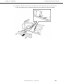
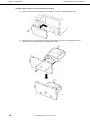
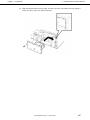
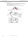
Extra Battery for RAID Controller ..................................................................................................... 60
1.9.1
Handling precautions ......................................................................................................... 60
1.9.2
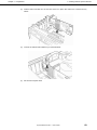
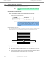
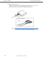
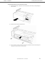
Installing N8103-121 extra battery ..................................................................................... 60
1.9.3
Installing N8103-141 extra battery ..................................................................................... 70
1.9.4
Removal ............................................................................................................................ 77
Express5800/GT110d-S
User’s Guide
Contents
1.10 PCI Card .......................................................................................................................................... 78
1.10.1
Notes ................................................................................................................................. 79
1.10.2
List of option devices and installation slots ........................................................................ 80
1.10.3
Installation.......................................................................................................................... 84
1.10.4
Configuration after installing .............................................................................................. 85
1.10.5
Removal ............................................................................................................................ 86
1.10.6
Installing the N8117-01A expansion RS-232C connector kit.............................................. 87
1.11 3.5-inch Hard Disk Drive .................................................................................................................. 90
1.11.1
Installation.......................................................................................................................... 91
1.11.2
Removal ............................................................................................................................ 93
1.12 2.5-inch Hard Disk Drive .................................................................................................................. 94
1.12.1
Installing an expansion 2.5-inch HDD cage ....................................................................... 95
1.12.2
Installation.......................................................................................................................... 97
1.12.3
Removal ............................................................................................................................ 98
1.12.4
Removing the 2.5-inch HDD cage for additional drives ..................................................... 98
1.13 Optical Disk Drive ............................................................................................................................ 99
1.13.1
Replacing drives ................................................................................................................ 99
1.13.2
Removal ............................................................................................................................ 99
1.14 Backup devices.............................................................................................................................. 100
1.14.1
Installation........................................................................................................................ 101
1.14.2
Removal .......................................................................................................................... 102
1.15 Connecting cables ......................................................................................................................... 103
1.15.1
Interface cables ............................................................................................................... 103
1.15.2
Power cables ................................................................................................................... 111
1.16 Attaching the Front Bezel............................................................................................................... 112
1.17 Installing the Side Cover ................................................................................................................ 113
2.
Ideal Location and Connection.................................................................................................................. 114
2.1
Ideal location for the server............................................................................................................ 114
2.1.1
2.2
Preparation for installation ............................................................................................... 116
Connection..................................................................................................................................... 119
2.2.1
Interface cables ............................................................................................................... 120
2.2.2
Power cord ...................................................................................................................... 122
Express5800/GT110d-S
User’s Guide
5
Contents
Chapter 3 Setup ................................................................................................................................................ 123
1.
Turning on the Server................................................................................................................................ 124
1.1
2.
3.
4.
POST ............................................................................................................................................. 125
1.1.1
POST sequence .............................................................................................................. 125
1.1.2
POST Error Messages..................................................................................................... 127
System BIOS Setup .................................................................................................................................. 128
2.1
Overview........................................................................................................................................ 128
2.2
Starting SETUP Utility .................................................................................................................... 128
2.3
Description on On-Screen Items and Key Usage .......................................................................... 129
2.4
Cases that Require Configuration.................................................................................................. 131
EXPRESSSCOPE ENGINE 3 ................................................................................................................... 133
3.1
Overview........................................................................................................................................ 133
3.2
EXPRESSSCOPE ENGINE 3 Network configuration .................................................................... 133
EXPRESSBUILDER.................................................................................................................................. 135
4.1
Features of EXPRESSBUILDER ................................................................................................... 135
4.2
Starting EXPRESSBUILDER ......................................................................................................... 135
5.
Installing Software Components................................................................................................................ 136
6.
Turning Off the Server............................................................................................................................... 137
Chapter 4 Appendix ........................................................................................................................................... 138
1.
2.
6
Specifications ............................................................................................................................................ 139
1.1
Air-cooling System ......................................................................................................................... 139
1.2
Water-cooling System .................................................................................................................... 140
Interrupt Lines ........................................................................................................................................... 141
Express5800/GT110d-S
User’s Guide
Notations Used in This Document
Notations Used in This Document
Notations used in the text
In addition to safety-related symbols urging caution, 3 other types of notations are used in this document. These
notations have the following meanings.
Important
Indicates critical items that must be followed when handling the server or operating software. If
the procedures described are not followed, server failure, data loss, and other serious
malfunctions could occur.
Note
Indicates items that must be confirmed when handling the server or operating software.
Tips
Indicates information that is helpful to keep in mind when using this server.
Optical disk drives
This server is equipped with one of the following drives, depending on the order at the time of purchase. These
drives are referred to as optical disk drives in this document.
• DVD-ROM drive
• DVD Super MULTI drive
Hard Disk Drives
Unless otherwise stated, Hard Disk Drives (HDD) described in this document refer to the following.
• Hard disk drives (HDD)
• Solid state drive (SSD)
Removable media
Unless otherwise stated, removable media described in this document refer to the following.
• USB memory
• Flash FDD
Express5800/GT110d-S
User’s Guide
7
Notations Used in This Document
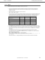
Abbreviations of Operating Systems
Windows Operating Systems are referred to as follows.
Notations in this document
Official names of Windows
Windows Server 2008 R2
Windows Server 2008 R2 Standard
Windows Server 2008 R2 Enterprise
Windows Server 2008 R2 Foundation
Windows Server 2008 Standard
Windows Server 2008 Enterprise
Windows Server 2003 R2 Standard x64 Edition
Windows Server 2003 R2 Enterprise x64 Edition
Windows Server 2003 R2 Standard Edition
Windows Server 2003 R2 Enterprise Edition
Windows Server 2003 Standard Edition
Windows Server 2003 Enterprise Edition
Windows Preinstallation Environment
Windows Server 2008*1
Windows Server 2003 R2 x64 Edition
Windows Server 2003 R2*2
Windows Server 2003*2
Windows PE
*1: Includes 64-bit and 32-bit Editions unless otherwise stated.
The following appears on EXPRESSBUILDER screen.
•
•
Windows Server 2008 64-bit Edition:
Windows Server 2008 32-bit Edition:
Windows Server 2008 x64
Windows Server 2008 x32
*2: Unless otherwise stated, Windows Server 2003 R2 and Windows Server 2003 are collectively referred to as
Windows Server 2003.
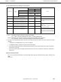
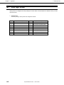
Supported Operating Systems differ depending on the model of this product. For details, see the following table.
Editions or Families of Windows
GT110d-S
Windows Server 2008 R2 Standard
Windows Server 2008 R2 Enterprise
Windows Server 2008 R2 Foundation
Windows Server 2008 Standard
Windows Server 2008 Enterprise
Windows Server 2003 R2 Standard x64 Edition*1
Windows Server 2003 R2 Enterprise x64 Edition*1
Windows Server 2003 R2 Standard Edition*1
Windows Server 2003 R2 Enterprise Edition*1
Windows Server 2003 Standard Edition*1
Windows Server 2003 Enterprise Edition*1
Windows PE
3
3
3
3
3
3
−
3
−
3
−
−*2
*1: Service Pack2 or later.
*2: Used as an installation platform only.
: Supported
−: Not supported
8
Express5800/GT110d-S
User’s Guide
Trademarks
Trademarks
ESMPRO and EXPRESSSCOPE are registered trademarks of NEC Corporation.
Microsoft, Windows, Windows Server, Windows Vista, and MS-DOS are registered trademarks or trademarks of Microsoft Corporation
in the United States and other countries. Intel, Pentium, and Xeon are registered trademarks of Intel Corporation of the United States.
AT is a registered trademark of International Business Machines Corporation of the United States and other countries. Adaptec, its
logo, and SCSI Select are registered trademarks or trademarks of Adaptec, Inc. of the United States. LSI and the LSI logo design are
trademarks or registered trademarks of LSI Corporation. Adobe, the Adobe logo, and Acrobat are trademarks of Adobe Systems
Incorporated. DLT and DLTtape are trademarks of Quantum Corporation of the United States. PCI Express is a trademark of
Peripheral Component Interconnect Special Interest Group. Linux is a trademark or registered trademark of Linus Torvalds in Japan
and other countries. Red Hat® and Red Hat Enterprise Linux are trademarks or registered trademarks of Red Hat, Inc. in the United
States and other countries.
All other product, brand, or trade names used in this publication are the trademarks or registered trademarks of their respective
trademark owners.
Express5800/GT110d-S
User’s Guide
9
Regulatory Notices
Regulatory Notices
FCC Statement
This equipment has been tested and found to comply with the limits for a Class A digital device, pursuant to
Part 15 of the FCC Rules. These limits are designed to provide reasonable protection against harmful
interference when the equipment is operated in a commercial environment. This equipment generates,
uses, and can radiate radio frequency energy and, if not installed and used in accordance with the
instruction manual, may cause harmful interference to radio communications. Operation of this equipment
in a residential area is likely to cause harmful interference in which case the user will be required to correct
the interference at his own expense.
CE Statement
This is a Class A product. In domestic environment this product may cause radio interference in which case
the user may be required to take adequate measures (EN55022).
BSMI Statement
10
Express5800/GT110d-S
User’s Guide
Warnings and Additions to This Document
Warnings and Additions to This Document
1.
Unauthorized reproduction of the contents of this document, in part or in its entirety, is
prohibited.
2.
The contents of this document may change without prior notice.
3.
Do not make copies or alter the document content without permission from NEC Corporation.
4.
Every effort has been made to ensure the completeness of this document. However, if you
have any concerns, or discover errors or omissions, please contact your retailer.
5.
Regardless of these 4 items, NEC Corporation assumes no responsibility for effects resulting
from operations.
6.
The sample values used in this document are not the actual values.
Keep this document nearby so that you may refer to it as necessary.
Latest editions
This document was created based on the information available at the time of its creation. The screen images,
messages and procedures may differ from the actual screens, messages and procedures. Substitute as
appropriate when content has been modified.
The most recent version of User’s Guide, as well as other related documents, is also available for download
from the following website.
http://www.nec.com/
Express5800/GT110d-S
User’s Guide
11
Precautions for Use (Be Sure to Read)
Precautions for Use (Be Sure to Read)
The following provides information required to use your server safely and properly. For details of names in this
section, refer to Names and Functions of Parts in this document.
Safety precautions
Follow the instructions in this document for the safe use of the NEC Express server.
This User’s Guide describes hazardous parts of the server, possible hazards, and how to avoid them. Server
components with possible danger are indicated with a warning label placed on or around them (or, in some
cases, by printing the warnings on the server).
In User’s Guide or on warning labels, WARNING or CAUTION is used to indicate a degree of danger. These
terms are defined as follows:
WARNING
Indicates there is a risk of death or serious personal injury
CAUTION
Indicates there is a risk of burns, other personal injury, or property damage
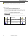
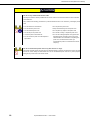
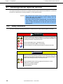
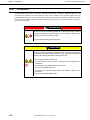
Precautions and notices against hazards are presented with one of the following three symbols. The individual
symbols are defined as follows:
Attention
This symbol indicates the presence of a hazard if
the instruction is ignored.
An image in the symbol illustrates the hazard type.
(Example)
(Electric shock risk)
Prohibited
Action
This symbol indicates prohibited actions. An image
in the symbol illustrates a particular prohibited
action.
(Example)
(Do not disassemble)
Mandatory
Action
This symbol indicates mandatory actions. An image
in the symbol illustrates a mandatory action to avoid
a particular hazard.
(Example)
(Disconnect a plug)
12
Express5800/GT110d-S
User’s Guide
Precautions for Use (Be Sure to Read)
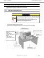
(A label example used in this User’s Guide)
Symbol to draw
attention
Description of a warning
Term indicating a degree of danger
WARNING
Use only the specified outlet
Use a grounded outlet with the specified voltage. Use of an improper power source
may cause a fire or a power leak.
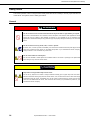
Symbols used in this document and on warning labels
Attentions
Indicates the presence of electric shock
hazards.
Indicates the presence of mechanical parts
that can result in bodily injury.
Indicates the presence of a hot surface or
component. Touching this surface could
result in bodily injury.
Indicates the presence of mechanical parts
that can result in pinching or other bodily
injury.
Indicates there is a risk of explosion.
Indicates the presence of laser beam that
cause blindness.
Indicates there is a risk of fire or fumes.
Indicates a general notice or warning that
cannot be specifically identified.
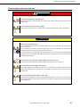
Prohibited Actions
Do not disassemble, repair, or modify the
server. Otherwise, an electric shock or fire
may be caused.
Do not touch the server with wet hand.
Otherwise, an electric shock may be
caused.
Do not touch the component specified by
this symbol. Otherwise, an electric shock or
burn may be caused.
Do not use the server in the place where
water or liquid may pour. Otherwise, an
electric shock or fire may be caused.
Do not place the server near the fire.
Otherwise, a fire may be caused.
Indicates a general prohibited action that
cannot be specifically identified.
Mandatory Actions
Unplug the power cord of the server.
Otherwise, an electric shock or fire may be
caused.
Indicates a mandatory action that cannot
be specifically identified. Make sure to
follow the instruction.
Make sure equipment is properly grounded.
Otherwise, an electric shock or fire may be
caused.
Express5800/GT110d-S
User’s Guide
13
Precautions for Use (Be Sure to Read)
Safety notes
This section provides notes on using the server safely. Read this section carefully to ensure proper and safe use
of the server. For symbols, refer to Safety precautions.
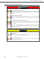
General
WARNING
Do not use the server for services where human life may be at stake or high reliability is required.
This server is not intended for use in medical, nuclear, aerospace, mass transit or other applications where
human life may be at stake or high reliability is required, nor is it intended for use in controlling such
applications. We disclaim liability for any personal injury and property damages caused by such use of this
server.
Do not use the server if any smoke, odor, or noise is present.
If smoke, odor, or noise is present, immediately turn off the server and disconnect the power plug from the
outlet, then contact the store where you purchased the product or your maintenance service company.
Using the server in such conditions may cause a fire.
Do not insert needles or metal objects.
Do not insert needles or metal objects into ventilation holes in the server or openings in the optical disk
drive. Doing so may cause an electric shock.
CAUTION
Keep water or foreign matter away from the server.
Do not let any liquid such as water or foreign materials including pins or paper clips enter the server.
Failure to follow this warning may cause an electric shock, a fire, or failure of the server. When such things
accidentally enter the server, immediately turn off the power and disconnect the power plug from the
outlet. Do not disassemble the server, and contact the store where you purchased the product or your
maintenance service company.
14
Express5800/GT110d-S
User’s Guide
Precautions for Use (Be Sure to Read)
Power supply and power cord use
WARNING
Do not hold the power plug with a wet hand.
Do not disconnect/connect the plug while your hands are wet. Failure to follow this warning may cause an
electric shock.
Do not connect the ground wire to a gas pipe.
Never connect the ground wire to a gas pipe. Failure to follow this warning may cause a gas explosion.
CAUTION
Plug in to a proper power source.
Use a grounded outlet and observe the specified voltage. Use of an improper power source may cause a
fire or a power leak.
Do not install the server where you need an extension cord. Use of a cord that does not meet the power
specifications of the server may heat up the cord and cause a fire.
If you want to use an AC cord set with a ground wire of class OI, be sure to connect the ground wire before
inserting the power plug into the outlet. Before disconnecting the ground wire, be sure to disconnect the
power plug from the output.
Do not connect many cords into a single outlet by using extension cords.
The electric current exceeding the rated flow overheats the outlet, which may cause a fire.
Do not pull out a cable by gripping the cable part.
Pull a cable straight out by gripping the connector part. Pulling a cable by gripping the cable part or
applying extra pressure to the connector part may damage the cable part, which may cause a fire or
electric shock.
Insert the power plug into the outlet as far as it goes.
Heat generation resulting from a halfway inserted power plug (imperfect contact) may cause a fire. Heat
will also be generated if condensation is formed on dusty blades of the halfway inserted plug, increasing
the possibility of fire.
Express5800/GT110d-S
User’s Guide
15
Precautions for Use (Be Sure to Read)
CAUTION
Do not use any unauthorized interface cable.
Use only the interface cables provided with the server. Electric current that exceeds the amount allowed
could cause fire.
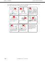
Also, observe the following precautions to prevent electrical shock or fire caused by a damaged power
cord.
• Do not stretch the cord harness
• Do not pinch the power cord
• Do not bend the power cord.
• Keep chemicals away from the power cord
• Do not twist the power cord
• Do not place any object on the power cord
• Do not step on the power cord.
• Do not alter, modify, or repair the power cord
• Uncoil the power cord before use
• Do not use a damaged power cord (replace the
• Do not secure the power cord with staples or
damaged power cord with a power cord of the
same standard. For information on replacing the
equivalents
power cord, contact the store where you
purchased the product or a maintenance service
company)
Do not use the attached power cord for any other devices or usage.
The power cord that comes with your server is designed aiming to connect with this server and to use with
the server, and its safety has been tested. Do not use the attached power cord for any other purpose.
Doing so may cause a fire or an electric shock.
16
Express5800/GT110d-S
User’s Guide
Precautions for Use (Be Sure to Read)
Installation, relocation, storage, and connection
CAUTION
Do not attempt to lift the server by holding the front bezel or air duct.
Securely hold the server by the base to move or lift. Do not attempt to lift it by holding the front bezel or air
duct. Doing so may cause the front bezel or air duct to come off, which may cause not only breakage of the
server but also cause the server to fall on to persons resulting in personal injury.
Do not install the server in any place other than specified.
Do not install the server in the following places or any place other than specified in this User's Guide.
Failure to follow this instruction may cause a fire.
• A dusty place
• A humid place such as near a boiler
• A place exposed to direct sunlight
• An unstable place
Do not use the server in an environment where corrosive gas is present
Do not install the server in a place subject to corrosive gases including sodium chloride, sulfur dioxide,
hydrogen sulfide, nitrogen dioxide, chlorine, ammonia, or ozone. Do not install the server in an
environment that contains dust, chemicals that accelerate corrosion such as NaCl or sulfur, or conductive
materials. Failure to follow this warning may cause the wiring on the printed wiring board to short-circuit,
leading to fire. If you have any questions, contact the store where you purchased the product or a
maintenance service company.
Do not connect or disconnect any interface cable with the power cord of the server plugged to a
power source.
Be sure to power off the server and unplug the power cord from a power outlet before installing/removing
any optional internal device or connecting/disconnecting any interface cable to/from the server. If the
server is off-powered but its power cord is plugged to a power source, touching an internal device, cable,
or connector may cause an electric shock or a fire resulted from a short circuit.
Use only the specified interface cable.
Use only interface cables provided by NEC and locate a proper device and connector before connecting a
cable. Using an authorized cable or connecting a cable to an improper destination may cause a short
circuit, resulting in a fire.
Also, observe the following notes on using and connecting an interface cable.
• Do not use any damaged cable connector.
• Do not step on the cable.
• Do not place any object on the cable.
• Do not use the server with loose cable connections.
• Do not use any damaged cable.
Express5800/GT110d-S
User’s Guide
17
Precautions for Use (Be Sure to Read)
Cleaning and working with internal devices
WARNING
Do not disassemble, repair, or alter the server.
Never attempt to disassemble, repair, or alter the server on any occasion except as described in this
document. Failure to follow this warning may cause not only malfunction of the server but also an electric
shock or fire.
Do not look into the optical disk drive
A laser beam used in the optical disk is harmful to the eyes. Do not look into or insert a mirror into the drive
while the drive is powered on. If a laser beam (which is invisible) enters your eyes, you may lose your
eyesight.
Do not attempt to remove lithium, NiMH, or Li-ion batteries.
The server contains the lithium, NiMH, or Li-ion battery (some optional devices have a lithium, NiMH, or
Li-ion battery installed). Do not remove the battery. Placing a battery close to a fire or in the water may
cause an explosion.
When the server does not operate appropriately due to the dead battery, contact the store you purchased
the product or your maintenance service company. Do not attempt to disassemble the server to replace or
recharge the battery by yourself.
CAUTION
High temperature
Components including internal Hard Disk Drives in the server are extremely hot just after the server is
turned off. Allow the surface to cool before installing/removing.
Secure cables or cards in place
Be sure to secure the power cord, interface cables, and cards in place. Incomplete installation causes a
loose connection, resulting in smoke or fire
18
Express5800/GT110d-S
User’s Guide
Precautions for Use (Be Sure to Read)
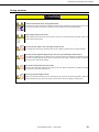
During operation
CAUTION
Avoid contact with the server during thunderstorms.
Do not touch any part of the server including the cables when a thunderstorm is approaching. Also, do not
connect or disconnect any devices. There may be a risk of electric shock from lightning strike.
Keep animals away from the server.
Keep animals such as pets away from the server. Pet hair or other waste enters the server, which may
cause a fire or electric shock.
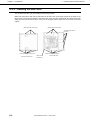
Do not place any object on top of vertically mounted servers.
Any weight on the server may cause the server to fall, resulting in personal injury or property damage.
Do not place any object that weighs 5 kg or more on top of horizontally mounted servers.
The maximum weight that can be placed on top of the server when it is horizontally mounted is 5 kg. Do
not place any object weighing 5 kg or more on top of the server. Failure to observe this limit may deform
the server, which could cause a failure.
Do not leave the optical disk drive tray open.
Dust may get in the server when the tray is open, which may result in a malfunction. In addition, bumping
the open tray could cause personal injury.
Do not get yourself caught in the fan
Keep your hands and hair away from the cooling fan at the rear of the server during operation. Failure to
observe this warning may cause your hands or hair to catch in the fan, resulting in personal injury.
Express5800/GT110d-S
User’s Guide
19
Precautions for Use (Be Sure to Read)
Warning labels
Warning label are attached on or near the components with potential hazards (This label is either attached or
printed on the component.) to draw attention from users to potential hazards involved in handling the server. (Do
not remove or black out this label and keep it clean). If no label is attached or printed on the server, or if there is
a label coming off or stained, contact the store where you purchased the product.
20
Express5800/GT110d-S
User’s Guide
Precautions for Use (Be Sure to Read)
Handling precautions (for proper operations)
Be sure to observe the following precautions for the proper functioning of the server. Ignoring the precautions
may cause server malfunction or failure.
• Do not use any cell phone or PHS and switch off them near the server. Electric waves from such
devices can cause server to malfunction.
• Install the server in an appropriate place. For details about the installation location, refer to Chapter 2
Preparations (2. Installation and Connection).
• Before connecting/removing cables to/from peripheral devices, make sure that the server is off and
unplug the power cord.
• Connect the provided power cord to a 100 VAC outlet. If an optional cable is used, you may connect
to a 100 or 200 VAC power system.
• Make sure that the access LED on the server is off before turning off the power or ejecting an optical
disk.
• Wait for at least 30 seconds before turning on the server after turning off the server. If any
Uninterruptible Power Supply unit is connected, set it to wait for at least 30 seconds before turning
on the server after power off.
• Turn off the server and unplug the power cord before moving it.
• Regularly clean the server to prevent various types of failure. (Refer to Chapter 1 Maintenance (2.
Daily Maintenance) in "Maintenance Guide" for details about cleaning.)
• Momentary voltage drop may occur due to lightning strike. To prevent this, use of UPS is
recommended.
• We do not guarantee that any copy-protected CD that does not conform to standards will play on the
CD player.
• Make sure that optional devices you are going to install are supported for use with the server. Even if
they are successfully installed or connected, installation of unsupported devices can cause the
server to malfunction or even failure.
• In the following cases, check and adjust the system clock before operation.
− After transportation
− After storage
− After the server is used following a period of disuse, in which storage conditions did not conform to those
that guarantee server operations (temperature: 10°C to 40°C; humidity: 20% to 80%).
Check the system clock approximately once per month. Use of a time server (NTP server) is
recommended if high accuracy timing is required by the system.
If you notice that the system clock runs significantly faster or slower over time even after adjustment,
contact the store where you purchased the product or your maintenance service company for repair.
• In order to get the server and internal devices to work properly, we recommend you store the server
at room temperature.
Observe the storage conditions (Temperature: −10°C to 55°C, Humidity: 20% to 80%) to store the
server. (No condensation of moisture)
Express5800/GT110d-S
User’s Guide
21
Precautions for Use (Be Sure to Read)
• If this server, internal optional devices, and media set for the backup devices (tape cartridges) are
moved from a cold place to a warm place in a short time, condensation will occur and cause
malfunctions and failures when these are used in such state. To protect important stored data and
property, make sure to wait for a sufficient period to use the server and components in the operating
environment.
Reference: Time effective at avoiding condensation in winter (10°C or more differences between the
room temperature and atmospheric temperature)
Disk devices: Approximately 2 to 3 hours
Tape media: Approximately 1 day
• For optional devices, we recommend you use our NEC products. Some memory or Hard Disk Drive
manufactured by other companies are supported for use with this server, however, you will be
charged to repair failure or damage caused by use of such products even within warranty period.
Tips
Maintenance service
We offer periodic diagnosis and maintenance services by staff with expert
knowledge of the maintenance of this server.
We recommend that you make a periodic maintenance service contract with your
maintenance service company to keep your server in good condition.
22
Express5800/GT110d-S
User’s Guide
Precautions for Use (Be Sure to Read)
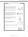
Tips for your health and safety
Using a computer extensively may affect different parts of your body. Here are tips you should follow while working on
a computer to minimize strain on your body.
Keep proper posture
The basic body position for using a computer is sitting straight with
your hands on the keyboard parallel with the floor, and your eyes
directed slightly downward toward the monitor. With the proper
posture described above, no unnecessary strain is applied on any
part of your body, in other words when your muscles are most
relaxed.
Working on the computer with bad posture such as hunching over or
being too close to the monitor could cause fatigue or deteriorated
eyesight.
Adjust the angle of your display
Most display units are designed for adjustment of the horizontal and
vertical angles. This adjustment is important to prevent the screen
from reflecting bright lights and to make the display contents easy to
see. Working without adjusting the display to a comfortable angle
makes it difficult for you to maintain a proper posture and you will
get tired easily. Adjust the viewing angle before use.
Adjust the brightness and contrast of the display
Display screens have functions to control brightness and contrast.
The most suitable brightness/contrast depends on age, individuals,
and environment, so adjust it to suit your preferences. A too bright
or too dark display is bad for your eyes.
Adjust the angle of keyboard
Some keyboards are ergonomically designed, which allow the angle
to be adjusted. Adjusting the angle of the keyboard is effective to
reduce tension on your shoulders, arms, and fingers.
Clean your equipment
Keeping your equipment clean is important not only for the appearance but also for functional and safety reasons. A
dusty monitor makes it difficult to see the display contents, so clean it regularly.
Take rest breaks
When you feel tired, take a break. Light exercise is also
recommended.
Express5800/GT110d-S
User’s Guide
23
NEC Express5800 Series
Express5800/GT110d-S
General Description
This chapter introduces the features of this server and the name of each part.
1. Introduction
2. Accessories
Verify the condition of your server's accessories.
3. Standard Features
Check and maintain the server system by using the functions explained in this section.
4. Names and Functions of Parts
This section describes the name of each part contained in this server.
.
24
Express5800/GT110d-S
User’s Guide
Chapter 1 General Description
1.
1. Introduction
Introduction
Thank you for purchasing this NEC Express5800 Series product.
This high performance server is powered by the latest Intel® processor. The type of processor installed depends
on the model.
• Intel® Xeon® processor
• Intel® Pentium® processor
• Intel® CoreTM i3 processor
NEC’s latest technology and architectures realize high-power and high-speed operation that cannot be matched
by existing servers.
The server is designed with consideration of not only reliability but also expandability, which enables you to use
it as a network server.
Read this document before using the server thoroughly to fully understand handling of the NEC Express server
and appreciate its functions to the maximum extent.
Express5800/GT110d-S
User’s Guide
25
Chapter 1 General Description
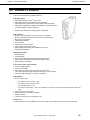
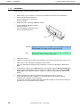
2.
2. Accessories
Accessories
The carton box contains various accessories which are required for setup or maintenance. Make sure you
have them all for future use.
•
•
•
•
•
•
•
•
•
•
•
*1
*2
*3
*4
*1
SATA cable × 2
Keyboard × 1
Mouse × 1
Air duct × 1
Rubber foot × 4
*2
Security key × 2
*3
Screw (503) × 1
*1
Screw (505) × 2
*4
EXPRESSBUILDER
Getting Started
Power cord x 1
Only for 3.5-inch disk models. The number of the cable depends on the Hard Disk Drive configuration.
Only for 2.5-inch disk models.
If an internal backup device is pre-installed, this is already attached.
Documents are stored in EXPRESSBUILDER. Adobe Reader is required to read the documents so make
sure you have it installed in your PC.
Make sure you have all accessories and inspect them. If an accessory is missing or damaged, contact your
sales representative.
26
Express5800/GT110d-S
User’s Guide
Chapter 1 General Description
3.
3. Standard Features
Standard Features
The server has the following standard features:
High performance
• Intel® Xeon®/Pentium®/CoreTM i3 processor
• High-speed memory access (DDR3 1333 supported)*
• High-speed disk access (SATA2 3 Gbps, SAS 6 Gbps supported)
• High-speed 1000BASE-T/100BASE-TX/10BASE-T (2 ports) interface
(1 Gbps/100 Mbps/10 Mbps supported)
*: Pentium G620 embedded models operate at 1066 MHz.
High reliability
• Memory monitoring feature (error correction/error detection)
• Memory degeneracy feature (logical isolation of a failed device)
• Bus parity error detection
• Temperature detection
• Error detection
• Internal fan monitoring feature
• Internal voltage monitoring feature
• RAID System (Disk Array) (also available as an option)
• BIOS password feature
Management utilities
• NEC ESMPRO
• ExpressUpdate
• Remote controlling featuer (EXPRESSSCOPE Engine 3)
• RAID System management utility (Universal RAID Utility)
• Hard Disk Drive monitoring
Power saving and noiseless design
• Power monitoring feature
• Power control feature
• High-efficiency power supply supporting 80 PLUS® Silver
• Fan control appropriate to environment, work load, and configuration
• Enhanced Intel SpeedStep® Technology supported
Expandability
• Many IO option slots
−
PCI Express 2.0 (x 16 lanes): 1 slot
−
PCI Express 2.0 (x 4 lanes): 2 slots
−
*
•
•
•
•
PCI (32 bits/33 MHz): 1 slot
For water-cooled models, 1 slot of PCI Express 2.0 (4 lanes) and PCI (32 bits/33 MHz) slot cannot be
used.
Large memory of up to 32 GB
Backup device bay provided as standard
USB2.0 interface
Three LAN ports (one for management LAN)
Ready to use
• Hard Disk Drives can be installed with one-touch setup, which requires no cables (hot swap supported)
Express5800/GT110d-S
User’s Guide
27
Chapter 1 General Description
3. Standard Features
Many built-in features
• El Torito Bootable CD-ROM (no emulation mode) format supported
• Software power-off
• Remote power-on feature
• AC-Link feature
• Remote console feature
• Baseboard Management Controller (BMC) conforming to IPMI v2.0
Self-diagnosis
• Power On Self-Test (POST)
• Test and Diagnosis (T&D) utility
Easy setup
• EXPRESSBUILDER (setup utility)
• SETUP (BIOS SETUP utility)
Maintenance features
• Off-line maintenance utility
• Memory dump feature using the DUMP switch
• Feature to back up and restore BIOS/BMC settings using the EXPRESSSCOPE profile key
28
Express5800/GT110d-S
User’s Guide
Chapter 1 General Description
3. Standard Features
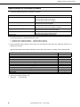
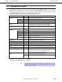
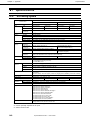
3.1 Management Features
The hardware components of the server provide operation control/reliability features as shown below.
Additionally, NEC ESMPRO Agent, which is provided in EXPRESSBUILDER, enables you to collectively
manage the state of your systems. You can also monitor the server states from a PC to manage the network
where NEC ESMPRO Manager provided in EXPRESSBUILDER is installed.
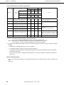
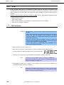
The features available on this server are as shown in the table below.
Function
Availability
Hardware
Description
Shows physical hardware information.
Memory bank
{
Shows physical memory information.
Device info
{
Shows information specific to the server.
CPU
{
Shows physical CPU information.
{
Shows logical CPU information and monitors the load factor.
System
Shows logical memory information and monitors the status.
I/O device
{
Shows information on I/O devices ( serial ports, keyboard, mouse, and
video).
System
environment
Temperature
{
Monitors the temperature inside of the chassis.
Fan
{
Monitors the fans.
Voltage
{
Monitors the voltage inside of the chassis.
Power supply
{
Monitors the power supply unit.
Door
×
Monitors chassis intrusion (open/close of the covers and doors on the
chassis).
Software
{
Shows service, driver, and OS information.
Network
{
Shows network (LAN) information and monitors packets.
BIOS
{
Shows BIOS information.
Local polling
{
Monitors the values of an MIB item obtained by NEC ESMPRO Agent.
Storage
{
Monitors controllers and storage devices including Hard Disk Drives.
File system
{
Shows the file system configuration and monitors the free space.
RAID System/Disk Array
{
Monitors the following RAID Controllers:
TM
• On-board RAID Controller (LSI Embedded MegaRAID )
• Optional RAID Controller N8103-128/129/130/134
Others*
{: Supported.
U: Partially supported.
{
Monitors OS stall using the Watch Dog Timer.
{
Performs alert processing after an OS STOP error occurs.
×: Unsupported.
*: Not displayed on the NEC ESMPRO Manager screen.
Tips
NEC ESMPRO Manager and NEC ESMPRO Agent are supplied with the server as
standard. For how to install and use each software component, refer to the
explanation of the component.
Express5800/GT110d-S
User’s Guide
29
Chapter 1 General Description
3. Standard Features
3.2 Firmware and Software Version Management
By using NEC ESMPRO Manager and ExpressUpdate Agent, you can manage firmware or software on the
server and update them by applying an update package.
This function automatically updates multiple modules without stopping the system just by specifying the
application of an update package from NEC ESMPRO Manager.
30
Express5800/GT110d-S
User’s Guide
Chapter 1 General Description
4.
4. Names and Functions of Parts
Names and Functions of Parts
Names and functions of parts are as follows.
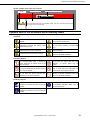
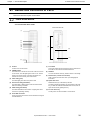
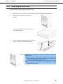
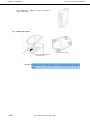
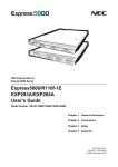
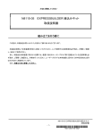
4.1 Front of the server
3.5-inch Hard Disk Drive model
Front bezel removed
(1)
(2)
(3)
(4)
(5)
(6)
(9)
(7)
(10)
(11)
(8)
(1) Air duct
(7) Front bezel
To take air to cool the server
This cover protects the front part of the server. Remove this
to handle 3.5-inch device and Hard Disk Drives.
(2) POWER switch
The switch to turn the server on and off. Press once to turn
(8) Stabilizer
on the server. The LED lights green when it is on. Press it
again to turn off the server. Hold down the switch for 4
To mount the server vertically, install as shown in the image
(9) Release tabs (3 at side of front bezel)
seconds or more to forcibly turn off the server.
Tabs to unlock the front bezel. Pull up to disengage the
(3) Power LED (green)
front bezel.
This LED lights green when the power is ON.
(10) Optical disk drive
(4) Disk access LED (green/amber)
Reads data from (or writes data to) the disk.
This LED lights or flashes green when the internal Hard
The drive provides the following: an eject button to eject the
Disk Drive is being accessed.
tray; an LED that indicates Hard Disk Drive access; and an
eject hole for forcibly ejecting the tray
(5) Status LED (green/amber)
This LED indicates the server status. It lights green when
(11) 3.5-inch device bay
the server is operating normally.
The bay which can accommodate 3.5-inch device.
(6) Front USB connectors
These connectors are used to connect devices that support
the USB interface.
Express5800/GT110d-S
User’s Guide
31
Chapter 1 General Description
4. Names and Functions of Parts
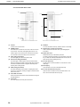
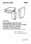
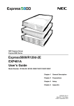
2.5-inch Hard Disk Drive model
(1)
(4)
(13)
(2)
(12)
(3)
(4)
(5)
(6)
(9)
(7)
(10)
(11)
(8)
(8) Stabilizer
(1) Air duct
To mount the server vertically, install as shown in the image
To take air to cool the server
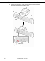
(9) Release tabs (3 at side of front bezel)
(2) POWER switch
The switch to turn the server on and off. Press once to turn
Tabs to unlock the front bezel. Pull up to disengage the
on the server. The Power LED lights green when it is on.
front bezel.
Press it again to turn off the server. Hold down the switch
(10) Optical disk drive
for 4 seconds or more to forcibly turn off, the server.
Reads data from (or writes data to) the disk.
The drive provides the following: an eject button to eject the
(3) Power LED (green/amber)
tray; an LED that indicates Hard Disk Drive access; and an
This LED lights green when the power is ON.
eject hole for forcibly ejecting the tray.
(4) Disk access LED (green/amber)
This LED lights or flashes green when the internal Hard
(11) 3.5-inch device bay
Disk Drive is being accessed. It lights amber when the drive
The bay which can accommodate 3.5-inch device or extra
is broken and flashes amber and green alternately when
HDD cage.
the array disk is being rebuilt.
(12) Security key
Locks the door of 2.5-inch Hard Disk Drive bays
(5) Status LED (green/amber)
This LED indicates the server status. It lights green when
(13) 2.5-inch Hard Disk Drive bay door
the server is operating normally and lights or flashes amber
Open this door to handle 2.5-inch Hard Disk Drives. This
when errors occur.
door can be locked with the security key.
(6) Front USB connectors
These connectors are used to connect devices that support
the USB interface.
(7) Front bezel
This cover protects the front part of the server.
32
Express5800/GT110d-S
User’s Guide
Chapter 1 General Description
4. Names and Functions of Parts
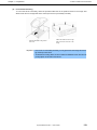
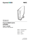
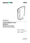
4.2 Rear view
3.5-inch Hard Disk Drive model and 2.5-inch Hard Disk Drive model
(1)
(5) (4)
(7)
(6)
(8)
(10)
(13)
(11) (11)
(2)
(9) (12)
(3)
(1) AC inlet
(7) BMC RESET switch (M RESET)
This socket is used to connect the power cord.
The switch to reset BMC of this server. Use the switch only
(2) PCI slots
when there is something wrong with EXPRESSSCOPE
(3) Chassis lock
Engine 3 (BMC).
The lock is provided to protect internal components from
(8) USB connectors
theft.
These connectors are used to connect devices that support
the USB interface.
(9) LAN connectors
1000BASE-T/100BASE-TX/10BASE-T supported Ethernet
connectors to connect to network system over LAN
(10) Management LAN port
An Ethernet connector which supports 100BASE-TX. This
(4) Serial port A connector
port is used for connection with EXPRESSSCOPE Engine
This connector is used to connect devices that support a
serial interface. Note that it is not possible to directly
connect to a dedicated line. If the N8117-01A additional
RS232C connector kit (available as an option), is
connected, the connector at N8117-01A will be the serial
port B connector.
3, and cannot be used as a data transmission port.
(11) LINK/ACT LED (green)
The LED indicates the access status of LAN
(12) Speed LED (green/amber)
The LED indicates the transfer speed of LAN ports
(13) Speed LED (green)
(5) Monitor connector
The LED indicates the transfer speed of the LAN port used
The connector to connect the monitor
for management
(6) DUMP switch
Press this switch to obtain a memory dump.
Important
Consult with the service technician of your maintenance service company to
control DUMP switch. If you control the switch while it is working fine, the
system will stop.
Tips
N8117-01A additional RS-232C connector kit can be installed on air-cooled models
only.
Express5800/GT110d-S
User’s Guide
33
Chapter 1 General Description
4. Names and Functions of Parts
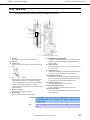
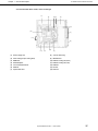
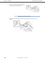
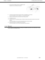
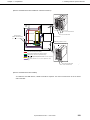
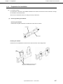
4.3 Internal view
3.5-inch Hard Disk Drive model, air-cooled type
(1)
(2)
(3)
(4)
(9)
(5)
(8)
(6)
(10)
(7)
(4)
(1)
Power supply unit
(6)
3.5-inch device bay
(2)
CPU cooling fan
(5)
Motherboard
(3)
DIMM slots
(8)
PCI slot
(4)
3.5-inch Hard Disk Drive
(9)
Rear fan
(5)
Optical disk drive
(10) Bottom fan
34
Express5800/GT110d-S
User’s Guide
Chapter 1 General Description
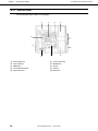
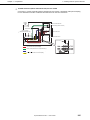
4. Names and Functions of Parts
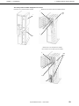
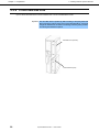
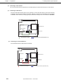
3.5-inch Hard Disk Drive model, water-cooled type
(1)
(2)
(3)
(4)
(12)
(5)
(11)
(6)
(10)
(9)
(8)
(7)
(4)
(1)
Power supply unit
(7)
Motherboard
(2)
Water cooling unit (for cooling CPU)
(8)
Radiator cooling fan (front)
(3)
DIMM slots
(9)
Radiator cooling fan (rear)
(4)
3.5-inch Hard Disk Drive
(10) Radiator
(5)
Optical disk drive
(11) PCI slots
(6)
3.5-inch device bay
(12) Rear fan
Express5800/GT110d-S
User’s Guide
35
Chapter 1 General Description
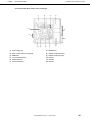
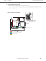
4. Names and Functions of Parts
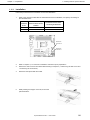
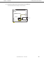
2.5-inch Hard Disk Drive model, air-cooled type
(1)
(2)
(3) (4)
(5)
(6)
(11)
(7)
(10)
(8)
(12)
(9)
(1)
Power supply unit
(7)
Optical disk drive
(2)
CPU cooling fan
(8)
3.5-inch device bay
(3)
DIMM slot
(9)
Motherboard
(4)
SAS backplane
(10) PCI slot
(5)
2.5-inch Hard Disk Drive
(11) Rear fan
(6)
HDD fan
(12) Bottom fan
36
Express5800/GT110d-S
User’s Guide
Chapter 1 General Description
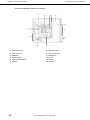
4. Names and Functions of Parts
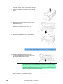
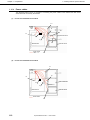
2.5-inch Hard Disk Drive model, water-cooled type
(1)
(2)
(3) (4)
(5)
(6)
(14)
(7)
(13)
(8)
(12)
(11)
(10)
(9)
(1)
Power supply unit
(8)
3.5-inch device bay
(2)
CPU cooling fan (for cooling CPU)
(9)
Motherboard
(3)
DIMM slot
(10) Radiator cooling fan (front)
(4)
SAS backplane
(11) Radiator cooling fan (rear)
(5)
2.5-inch Hard Disk Drive
(12) Radiator
(6)
HDD fan
(13) PCI slot
(7)
Optical disk drive
(14) Rear fan
Express5800/GT110d-S
User’s Guide
37
Chapter 1 General Description
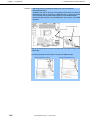
4. Names and Functions of Parts
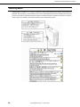
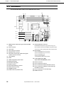
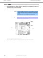
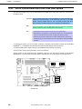
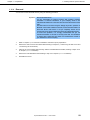
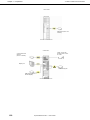
4.4 Motherboard
3.5-inch Hard Disk Drive model, 2.5-inch Hard Disk Drive model
(21)
(25)
(2)
(1)-2
(1)-4
(1)-1
(1)-3
(19)
(24)
(2)
(20)
(3)
(4)
(5)
(12)
(8)
(6)-0
(18)-1
(18)-2
(6)-1
(6)-2
(6)-3
(6)-4
(6)-5
(18)-3
(18)-4
(17)
(1)
(16)
DIMM slots (the number after hyphen indicates DIMM
(13) (15) (11) (10)(9) (14) (7)
(22) (23)
(17) SPI Flash Mezzanine connector
number)
EXPRESSSCOPE profile key (SPI flash memory) has
(2)
Power connector
been installed, where BIOS and BMC configuration data is
(3)
CPU socket
stored. Move it when replacing MB to keep using the data.
(4)
CPU cooling fan connector
(5)
RAID LED cable connector
(6)
Serial ATA connector (the number after hyphen
(18) PCI card slots
(18)-1 PCI EXPRESS x4 (x8 connector)
(18)-2 PCI EXPRESS x4 (x8 connector)
(18)-3 PCI EXPRESS x16*
indicates connector number)
(18)-4 PCI 32 bits/33 MHz*
(7)
Lithium battery
* Not available for water-cooled models.
(8)
Buzzer
(9)
CMOS configuration jumper switch
(10) RAID switch jumper
(11) Password clear jumper
(12) SGPIO connector
(13) Internal Flash Memory connector
(19) (Lower) DUMP switch (NMI)
(Upper) BMC RESET(M RESET) switch
(20) External connector
(21) Fan 2 connector (for rear fan)
(22) Fan 3 connector (for bottom fan/radiator rear fan)
(23) Fan 4 connector (for additional 2.5-inch HDD cage
(14) USB connector (for front)
(15) LED/SW connector
(16) COM B connector (for N8117-01A)
38
fan/radiator front fan)
(24) Fan 5 connector (for 2.5-inch HDD cage)
(25) PM-BUS connector
Express5800/GT110d-S
User’s Guide
Chapter 1 General Description
4. Names and Functions of Parts
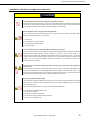
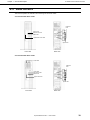
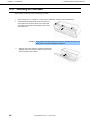
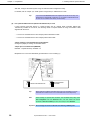
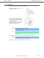
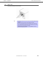
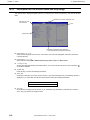
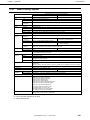
4.5 Status Indicators
This section explains the indication and meanings of the server LEDs.
3.5-inch Hard Disk Drive model
LINK/ACT
LED
Power LED
DISK access LED
Status LED
Optical disk access LED
Speed LED
Rear view
Front view
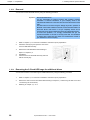
2.5-inch Hard Disk Drive model
Disk LED
LINK/ACT
LED
Power LED
Disk access LED
Status LED
Optical disk LED
Speed LED
Rear view
Front view
Express5800/GT110d-S
User’s Guide
39
Chapter 1 General Description
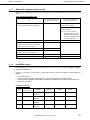
4.5.1
4. Names and Functions of Parts
Power LED (
)
The power LED lights green while the server is on.
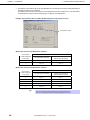
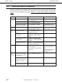
4.5.2
Status LED (
)
While hardware is operating normally, the status LED lights green. The status LED is off or lights/flashes
amber if there is a problem with hardware.
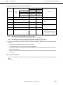
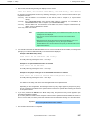
The following table lists status LED patterns, their explanation and solution.
Tips
Refer to the system event log (SEL) by using ESMPRO or the offline maintenance
utility to view the cause of failure.
If shutdown processing can be performed via the operating system when you want
to restart the system after turning the power off, restart the system by performing
shutdown processing. If shutdown processing cannot be performed, restart the
system by resetting the system, forcibly turning the power off or disconnecting and
then connecting the power cord.
Status LED pattern
Explanation
Solution
−
On (green)
The server is operating normally.
Flashing (green)
The server is operating with the memory in degraded Identify the device in degraded state by using the BIOS
state.
setup utility SETUP, and replace it as soon as possible.
An uncorrectable memory error has often occurred.
Off
The power is off.
Turn on the server.
POST is in progress.
Wait for a while. The STATUS LED will turn green after
POST completes.
Turn the power off and then turn it on. If the POST
A CPU error occurred.
screen displays any error message, take notes of the
Abnormal CPU temperature is detected.
message, and contact your maintenance service
Watchdog timer expired.
company.
An uncorrectable error in memory is detected.
A PCI system error occurred
A PCI parity error occurred
A PCI bus error occurred.
Memory dump is being requested.
Wait until the memory dump is completed.
(e.g. when DUMP switch NMI is pressed)
Note It remains green if the dump is caused by
software.
On (amber)
A temperature alarm was detected.
Check the internal fan for dusts. Also check if the fan
unit is properly connected.
If the LED indication does not change when the fans are
normal, contact your maintenance service company.
A voltage alarm was detected.
Contact your maintenance service company.
A CPU temperature alarm was detected.
SMI timeout is detected
40
Express5800/GT110d-S
User’s Guide
Chapter 1 General Description
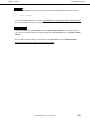
4. Names and Functions of Parts
Status LED pattern
Flashing (amber)
Explanation
Solution
Connect the power cord to supply power. If the power
Failure of the power supply unit is detected
supply unit is faulty, contact your maintenance service
company.
Check if the internal fan cable is properly connected. If
A fan alarm was detected.
the LED indication does not change when the fans are
normal, contact your maintenance service company.
Check the internal fan for dusts. Also check if the fan
A temperature warning was detected.
unit is properly connected.
If the LED indication does not change when the fans are
normal, contact your maintenance service company.
Contact your maintenance service company.
A voltage warning was detected
An error was detected on either of the Hard Disk
Drives.
An error is detected with Node Manager
4.5.3
Disk access LED (
)
The disk access LED lights or flashes green when an internal Hard Disk Drive or the optical disk drive is
being accessed. If a 2.5-inch Hard Disk Drive model is used in RAID System by using an optional RAID
Controller, the LED lights amber and green alternately when the Hard Disk Drive failed and flashes when it is
being rebuilt.
Tips
For 3.5-inch Hard Disk Drive model, the LED does not light/flashes amber when
Hard Disk Drive is broken or being rebuilt.
4.5.4
Optical disk access LED
The ACCESS LED lights/flashes when the media set on the optical disk drive is being accessed.
4.5.5
Disk LED
For 2.5-inch Hard Disk Drive model, each drive has its respective LED. When the Hard Disk Drive is
accessed, the LED lights/flashes green. In RAID System, when a Hard Disk Drive failed, the LED lights
amber and then flashes amber when it is being rebuilt.
4.5.6
LINK/ACT LED (
1,
2,
M)
This LED indicates the state of the standard network port. If the server and HUB is supplied with power and
connected properly, the LED is on (LINK). If the network port is transmitting/receiving data, the LED flashes
(ACT).
If the LED does not turn on in LINK state, check the cable or connection. If the LED remains off, the network
(LAN) controller may be defective. Contact the store where you purchased the product or your maintenance
service company.
Express5800/GT110d-S
User’s Guide
41
Chapter 1 General Description
4.5.7
Speed LED (
4. Names and Functions of Parts
1,
2,
M)
This LED indicates which network interface is used.
− The two LAN connectors for data transmission support 1000BASE-T, 100BASE-TX, and 10BASE-T
and the LED indicates which network interface is being used.
• Amber: Operating with 1000BASE-T
• Green: Operating with 100BASE-TX
• OFF:
Operating with 10BASE-T
− The LAN connector used for management supports 100BASE-TX and the LED flashes green during
the operation.
42
Express5800/GT110d-S
User’s Guide
NEC Express5800 Series
Express5800/GT110d-S
Preparations
This chapter describes preparations for using this server.
1. Installing Internal Optional Devices
You can skip this section if you did not purchase any optional devices.
2. Ideal Location and Connection
You must place the server in an ideal location and connect some cables following this section.
Express5800/GT110d-S
User’s Guide
43
Chapter 2 Preparations
1.
1. Installing Internal Optional Devices
Installing Internal Optional Devices
This chapter describes the instructions for installing supported optional devices and precautions. If you did not
purchase any optional device requiring installation, you may skip this section.
Important
• We recommend that optional devices be installed by a maintenance
service staff from your maintenance service company, who has
specialized knowledge of this server.
• Use only the devices and cables specified by NEC. You will be charged to
repair damages, malfunctions, and failures caused by the use of any
devices or cables not specified for use with this server even within the
warranty period.
1.1
Safety Precautions
Be sure to observe the following precautions to install and remove optional devices properly and safely.
WARNING
Be sure to observe the following precautions to use the server safety. Failure
to observe the precautions may cause death or serious injury. For details, refer
to Safety precautions in Precautions for Use.
• Do not disassemble, repair, or modify the server.
• Do not remove the lithium, NiMH, or Li-ion battery.
• Do not handle the server while the power plug is inserted into the outlet.
CAUTION
Be sure to observe the following precautions to use of the server safely. Failure
to observe the precautions may cause burns, injury, and property damage. For
details, refer to Safety precautions in Precautions for Use.
• Do not attempt to lift the server by gripping the front bezel or air duct.
• Make sure to complete installation.
• Do not get your fingers caught.
• High temperature.
44
Express5800/GT110d-S
User’s Guide
Chapter 2 Preparations
1.2
1. Installing Internal Optional Devices
Anti-static Measures
The server contains electronic components sensitive to static electricity. Avoid failures caused by static
electricity when installing or removing any optional devices.
•
Wear a wrist strap (an arm belt or anti-static glove)
Wear a wrist strap on your wrist. If no wrist strap is available, touch an unpainted metal part of the cabinet
before touching a component to discharge static electricity from your body.
Also discharge static electricity by periodically touching a metal surface while working on the components.
•
•
Select a suitable work space
−
Work with the server on the anti-static or concrete floor.
−
When you work with the server on a carpet where static electricity is likely to be generated, be sure to
take anti-static measures beforehand.
Use a work table
Place the server on an anti-static mat to work with.
•
•
Clothing
−
Do not wear wool or synthetic clothes.
−
Wear anti-static shoes.
−
Take off any jewels (a ring, bracelet, or wrist watch) before working with the server.
Handling of components
−
Keep any component in an anti-static bag until you actually install it to the server.
−
Hold any component by its edge to avoid touching any terminals or parts.
−
To store or carry any component, place it in an anti-static bag.
Express5800/GT110d-S
User’s Guide
45
Chapter 2 Preparations
1.3
1. Installing Internal Optional Devices
Overview of Installation and Removal
Install/remove components by using the following procedure.
1.
If the server is ON, turn it off.
Refer to Chapter 3 (6. Turning Off the Server).
2.
Disconnect the power cord from the outlet and the server.
3.
Disconnect all cables connected to the connector at the rear.
4.
Remove the side cover.
Refer to Chapter 2 (1.4. Removing the Side Cover).
5.
Remove the front bezel if applicable.
Refer to Chapter 2 (1.5 Removing the Front Bezel).
6.
Depending on the components to be installed or removed, follow the procedure in order.
Refer to Chapter 2 (1.6 Internal Flash Memory) to (1.14 Backup devices).
7.
Connect cables
Refer to Chapter 2 (1.15 Connecting cables).
8.
Attach the front bezel.
Refer to Chapter 2 (1.16 Attaching the Front Bezel).
9.
Attach the side cover.
Refer to Chapter 2 (1.17 Installing the Side Cover).
This is the end of the installation or removal procedures for internal optional devices.
Continue the setup with reference to Chapter 2 (2.2 Connection).
46
Express5800/GT110d-S
User’s Guide
Chapter 2 Preparations
1.4
1. Installing Internal Optional Devices
Removing the Side Cover
Remove the side cover by using the following procedure.
1.
Refer to steps 1 to 3 in Chapter 2 (1.3 Overview of Installation and Removal) for preparations.
2.
Unlock the padlock attached to the chassis if
applicable.
3.
Lay it so that the side cover faces upward. Lay it
down slowly and gently.
4.
Remove the side cover. While pressing the two eject
buttons, slide the cover backward and lift it off.
Eject button
Eject button
Important BRACKET KEY: This equipment is intended for installation in a location with
restricted access.
Access can only be gained by service persons or by users who have
been instructed about the reasons for the restrictions applied to the
location and about any precautions to be taken.
Access can be obtained through the use of a special tool or lock and
key, or other means of security. This tool is controlled by the authority
responsible for the location.
Express5800/GT110d-S
User’s Guide
47
Chapter 2 Preparations
1.5
1. Installing Internal Optional Devices
Removing the Front Bezel
Remove the front bezel by using the following procedure.
1.
Refer to steps 1 to 3 in Chapter 2 (1.3 Overview of Installation and Removal) for preparations.
2.
Release the three release tabs on the front bezel (1)
in the direction of the arrow shown in the image and
then pull the front bezel forward slightly until it comes
off the frame (2).
Important
If you pull the front bezel forward too much, you will break the lower hook.
Gently slide it to prevent damaging the equipment.
3.
48
Slide the front bezel upward to release the hooks that
engaged with the three holes at the lower part of the
server and take it off the server.
Express5800/GT110d-S
User’s Guide
Chapter 2 Preparations
1.6
1. Installing Internal Optional Devices
Internal Flash Memory
This section describes the procedure for installing the Internal Flash Memory.
Internal USB connector
1.6.1
Installation
Install the Internal Flash Memory in the following procedure.
1.6.2
1.
Refer to steps 1 to 5 in Chapter 2 (1.3 Overview of Installation and Removal) for preparations.
2.
Attach the Internal Flash Memory and fix
it with the screw provided with this
product.
Removal
To remove the Internal Flash Memory, reverse the installation procedure.
Express5800/GT110d-S
User’s Guide
49
Chapter 2 Preparations
1.7
1. Installing Internal Optional Devices
DIMM
Install a DIMM (Dual In-line Memory Module) to a DIMM slot on the motherboard in the server. The
motherboard provides four slots to install DIMMs.
Up to 32 GB (8 GB × 4) of memory can be installed.
Important
• Use only the DIMMs specified by NEC. Installing a DIMM from a third party
may cause the server to fail. (You will be charged to repair failures or
damages caused by the use of such products even within the warranty
period.)
• Read through Chapter 2 (1.2 Anti-static Measures) beforehand.
Tips
As about 750 MB of memory is used for PCI resources, the available memory size
may be less than the mounted memory size.
DIMM2
DIMM4
DIMM1
DIMM3
Rear
Front
Motherboard
This server supports Dual Channel memory mode.
If you run the server in Dual Channel mode, the data transfer speed of the memory doubles.
50
Express5800/GT110d-S
User’s Guide
Chapter 2 Preparations
1.7.1
1. Installing Internal Optional Devices
Maximum supported memory size
The maximum available memory size on the server depends on the architecture (x86 architecture) and OS
specs.
A list of maximum memory sizes
OS
Windows Server 2003 R2 Standard Edition
The maximum memory size
The maximum memory size
supported on each OS
supported on the server
4 GB
4 GB (If using HW-DEP function)
Windows Server 2008 Standard x86 Edition
* Default factory settings
About 3.3 GB (If not using
HW-DEP function)
Note: If you are not using the
HW-DEP function, set the
Execute Disable Bit (XD Bit)
to Disable in the BIOS setup.
It is enabled by default.
Windows Server 2008 R2 Foundation
8 GB
8 GB
Windows Server 2003 R2 Standard x64 Edition
32 GB
32 GB
Windows Server 2008 Standard x64 Edition
Windows Server 2008 R2 Standard
Windows Server 2008 Enterprise x86 Edition
64 GB
Windows Server 2008 Enterprise x64 Edition
2 TB
Windows Server 2008 R2 Enterprise
1.7.2
RedHat Enterprise Linux 5 Server (x86)
16 GB
16 GB
RedHat Enterprise Linux 5 Server (EM64T)
256 GB
32 GB
Installation order
Install DIMMs one by one in order of increasing memory size into slots in the order of DIMM#1, DIMM#2,
DIMM#3, and DIMM#4.
However, if you want to run the server in Dual Channel mode, observe the following when installing the
DIMMs:
•
•
•
Install them in pairs
The two memories installed together must be of the same specifications and memory size.
Install the pairs as DIMM#1 and DIMM#2, or DIMM#3 and DIMM#4 (the installation order between the
pairs does not matter.)
Installation examples
Example
1
Dual Channel
Memory mode
Runs
DIMM#1
2 GB DIMM
DIMM#2
DIMM#3
DIMM#4
2 GB DIMM
Not installed
Not installed
2 GB DIMM
2 GB DIMM
2 GB DIMM
2 GB DIMM
2 GB DIMM
Not installed
2 GB DIMM
Not installed
2GB DIMM
(Standard)
2
Runs
2 GB DIMM
(Standard)
3
Does not run
2 GB DIMM
(Standard)
4
Does not run
2 GB DIMM
(Standard)
Express5800/GT110d-S
User’s Guide
51
Chapter 2 Preparations
1.7.3
1. Installing Internal Optional Devices
Installation
Install a DIMM by using the following procedure.
1.
Refer to steps 1 to 5 in Chapter 2 (1.3 Overview of Installation and Removal) for preparations.
2.
Hold the server with both hands and
slowly and gently lay it so that the left
side faces upward
3.
Rotate both levers of the target DIMM slot outward.
4.
Hold the DIMM vertically and push it all
the way into the slot.
When the DIMM is inserted into the slot,
the lever automatically closes.
Key slot
Key
Important
Applying too much pressure on a DIMM or inserting a DIMM at an angle may
break the DIMM or slot. Gently insert it straight into the slot.
Note
Make sure the DIMM is oriented correctly. The terminal side of a DIMM has the
key and keyslot, preventing being wrongly inserted.
52
5.
Firmly close the lever.
6.
Continue to install or remove internal optional devices, mount and connect the server, and turn it on.
7.
Confirm that no error messages are displayed in POST screen.
If any error messages are displayed, refer to Chapter 3 (1. POST Error Message) in "Maintenance
Guide".
8.
Run the SETUP Utility, go to the Advanced menu, and check the display in Memory Configuration.
Confirm that the added DIMM has been recognized in the BIOS (Confirm that the applicable DIMM
Group Status is set to Normal.). (Refer to Chapter 2 (1. Details of System BIOS) in "Maintenance
Guide".)
9.
Set the paging file size to the recommended value (Total memory size x 1.5) or more.
If using a Windows OS, refer to Chapter 1 (7.1 Specifying Memory Dump Settings (Debug
Information)) in "Installation Guide (Windows)".
For other OS, consult the manual provided with the operation system or contact the store where you
purchased it or your maintenance service company.
Express5800/GT110d-S
User’s Guide
Chapter 2 Preparations
1.7.4
1. Installing Internal Optional Devices
Removal
Remove a DIMM in the following procedure.
Note
• When removing a defective DIMM, check error messages displayed at POST or
ESMPRO and check the DIMM slot where the defective DIMM is installed.
• At least one DIMM needs to be installed for the server to operate.
1.
Refer to steps 1 to 5 in Chapter 2 (1.3 Overview of Installation and Removal for preparations.
2.
Rotate both levers of the target DIMM
slot outward.
The DIMM is unlocked
3.
Remove the DIMM by pulling it out from
the slot in a straight direction.
Important
Applying too much pressure on a DIMM or pulling a DIMM at an angle
may break the DIMM or slot. Gently pull it straight out of the slot.
4.
Assemble the server.
5.
Turn on the server and confirm that no error messages are displayed on POST. If any error message
is displayed, refer to Chapter 3 (1. Post Error Message) in "Maintenance Guide".
6.
If you replaced a broken DIMM, select Yes in Memory Configuration-Memory Retest of the
Advanced menu.
After that, select Save Changes and Exit to reboot.
7.
Set the paging file size to the recommended value (Total memory size x 1.5) or more.
If using a Windows OS, refer to Chapter 1 (7.1 Specifying Memory Dump Settings (Debug
Information)) in "Installation Guide (Windows)".
For other OS, consult the manual provided with the operation system or contact the store where you
purchased it or your maintenance service company.
Express5800/GT110d-S
User’s Guide
53
Chapter 2 Preparations
1.8
1. Installing Internal Optional Devices
Use of Internal Hard Disk Drives in the RAID System
This section describes how to use the Hard Disk Drives installed in the HDD cage at the front of the server in
the RAID System.
Important
If you use Hard Disk Drives in the RAID System or change the RAID level,
initialize the Hard Disk Drives. If the Hard Disk Drive used in the RAID
System contains valuable data, be sure to backup the Hard Disk Drive
before installing the RAID Controller and configuring the RAID System.
Note
In the RAID System, use Hard Disk Drives that have the same specifications
(capacity, rotational speed, and standard) for each Disk Array.
Tips
• Logical Drives can be created even with only one Physical Device.
• Understand the characteristics of each RAID Controller such as available RAID
levels or Hard Disk Drives and choose an appropriate RAID Controller.
• Logical Drives except for RAID0 have a smaller usable capacity compared to
the total capacity of the Hard Disk Drive in the Logical Drive, while disk reliability
increases.
To configure the system, you can use either a software- controlled on-board RAID Controller (LSI Embedded
MegaRAIDTM) or a hardware-controlled optional RAID Controller (N8103-128/129/130/134).
To use this RAID System, jumper settings on motherboard and backplane are required.
For the location of the jumpers and setting, refer to the following.
Jumper settings on the motherboard and backplane required to use the RAID Controller (LSI Embedded
MegaRAIDTM) or optional RAID Controllers (N8103-128/129/130/134) are described in the images below.
3 2 1
3 2 1
Enabled
Disabled
SWRAID jumpers
Motherboard
54
Express5800/GT110d-S
User’s Guide
Chapter 2 Preparations
1. Installing Internal Optional Devices
1
2
3
N8103-128/129/130/134
1
2
3
On-board SATA
controller
Backplane for 2.5-inch Hard Disk Drives
(Installed on 2.5-inch model as standard)
(a)
When using on-board RAID Controllers (LSI Embedded MegaRAIDTM)
By changing the jumper setting for RAID configuration on the motherboard, the internal Hard Disk Drive can
be recognized as a software-controlled RAID System Hard Disk Drive.
Jumper settings on the motherboard and backplane
Change the jumper pin settings as described below.
Jumper pins on motherboard (SWRAID)
Enabled: 2-3 / Disabled: 1-2 (Default value)
Backplane for 2.5-inch Hard Disk Drive (provided with 2.5-inch models) (J7)
1
2
3
N8103-128/129/130/134
Express5800/GT110d-S
1
2
3
User’s Guide
On-board SATA
controller
55
Chapter 2 Preparations
1. Installing Internal Optional Devices
After that, configure the RAID System using LSI Software RAID Configuration Utility.
For details, refer to Chapter 2 (4. RAID System Configuration) in "Maintenance Guide".
Tips
If you use the EXPRESSBUILDER DVD supplied with the server for setup, the
RAID System is automatically configured. Or, you intend to install Windows OS,
OS also can be installed automatically and seamlessly.
(b)
If an optional RAID Controller (N8103-128/129/130/134) is used
If using internal Hard Disk Drives in a RAID System with an optional RAID Controller (N8103-128/
129/130/134) installed in the server, the following cable is required instead of using the interface cable
supplied with the server.
−
For 3.5-inch Hard Disk Drives: K410-253(00) internal SAS/SATA cable
−
For 2.5-inch Hard Disk Drives: K410-180(00) internal SAS cable
Jumper settings on the motherboard and backplane
Change the jumper pin settings as described below.
Jumper pins on motherboard (SWRAID)
Disabled: 1-2 (Default value) / Enabled: 2-3
Backplane for 2.5-inch Hard Disk Drive (provided with 2.5-inch models) (J7)
1
2
3
N8103-128/129/130/134
Tips
1
2
3
On-board SATA
controller
N8103-128/129 and N8103-128/129/130/134 are to be connected for 3.5-inch
Hard Disk Drive model and for 2.5-inch Hard Disk Drive model respectively.
Note
When installing an optional RAID Controller, start the BIOS Setup utility, select
PCI Configuration from the Advanced menu, and then make sure that the
parameter of PCI Slot xx ROM (xx is PCI slot number) is set to Enabled.
Important
56
Do not change the mode to hibernate when building a RAID System.
Express5800/GT110d-S
User’s Guide
Chapter 2 Preparations
(c)
1. Installing Internal Optional Devices
Installation
For the instruction of installing the optional RAID Controller (N8103-128/129/130/134), refer to Chapter 2
(1.10 PCI Card).
Important
When connecting a RAID Controller, set the boot priority to 8th or higher in
the Boot menu of the BIOS Setup utility. If the setting is 9th or lower, the
configuration menu for RAID Controllers cannot be launched.
(d)
Removal
To remove the optional RAID Controller (N8103-128/129/130/134), reverse the installation procedure.
If you intend to use with the card removed, be sure to attach the slot cover attached to the riser card. The slot
cover must be screwed into place.
1.8.1
Notes on setting up a RAID System
Note the following points when setting up a RAID System.
•
The number of Hard Disk Drives required varies in each RAID level.
•
If an on-board RAID Controller or optional RAID Controller (N8103-128/129) is used, the RAID System
cannot be built in RAID5/RAID6.
The minimum number of Hard Disk Drives required to set up a RAID System
RAID level
On-board RAID Controller or
N8103-128/129
N8103-130/134
RAID 0
1
1
RAID 1
2
2
RAID 5
3
RAID 6
3 (N8103-130), 4 (N8103-134)
RAID 10
4
4
RAID 50
6
•
Use SAS/SATA Hard Disk Drives or SSDs that have the same capacity and rotational speed.
•
As the size of Logical Drive cannot be specified in RAID 10 with the on-board RAID Controller, the
Logical Drive size will be at least 4 TB if a Hard Disk Drive of 2 TB or more is used. However, the
Logical Drive where the OS is to be installed may be up to 2 TB due to OS restrictions, and therefore
RAID 10 using a Hard Disk Drive of 2 TB or more cannot be supported if an on-board RAID Controller is
used.
When installing an OS in your RAID System, you can easily complete the setup process, including RAID
configuration and OS installation, by using EXPRESSBUILDER. If you are installing the OS manually, use
the RAID System configuration utility. The utility can be run during POST which starts immediately after the
server is turned on. For details on the procedure of configuring a Logical Drive, refer to Chapter 2 (4. RAID
System Configuration) in "Maintenance Guide" or the manual supplied with the optional RAID Controller
(N8103-128/129/130/134).
Important
• Do not change the RAID System mode to hibernate.
• A mix of SAS and SATA drives cannot be used within the RAID System.
• Before configuring RAID System using EXPRESSBUILDER, be sure to
clear the configuration information of the RAID Controller by referring to
the manual of the relevant controller.
Express5800/GT110d-S
User’s Guide
57
Chapter 2 Preparations
•
1. Installing Internal Optional Devices
The display of slot numbers (SLT) for Hard Disk Drives in the OS system event log varies depending on
the RAID Controller to be connected.
The tables below show the insert position of Hard Disk Drives and slot numbers (SLT). The information
on these tables is important when checking logs or replacing a Hard Disk Drive.
Example: Slot numbers (SLT) for HDD and SSD displayed in OS system event log
Slot number to install
Models with 3.5-inch Hard Disk Drives installed
Slot numbers indicated
Insert position
numbers displayed
Optional RAID Controllers
on the server
On-board RAID Controllers
0
SLT = 1
SLT = 1
1
SLT = 2
SLT = 2
(N8103-128/129/130/134)
Models with 2.5-inch Hard Disk Drives installed
Slot numbers indicated
Insert position
numbers displayed
Optional RAID Controllers
on the server
On-board RAID Controllers
0
SLT = 1
SLT = 1
1
SLT = 2
SLT = 2
2
SLT = 3
SLT = 3
4
SLT = 4
SLT = 4
5
SLT = 5
SLT = 5
Tips
(N8103-128/129/130/134)
The insert position number displayed on the server starts from 0.
SLT of on-board/optional RAID Controllers displayed starts from 1.
58
Express5800/GT110d-S
User’s Guide
Chapter 2 Preparations
1. Installing Internal Optional Devices
The insert position number displayed on the server
Models with 3.5-inch Hard Disk Drives installed
Models with 2.5-inch Hard Disk Drives installed (standard)
0
HDD
cage
1
1
2
0
Models with 2.5-inch Hard Disk Drives installed
(when expansion 2.5-inch HDD cages are installed)
0
HDD
cage
1
2
4
5
Express5800/GT110d-S
User’s Guide
59
Chapter 2 Preparations
1.9
1. Installing Internal Optional Devices
Extra Battery for RAID Controller
If a RAID Controller (N8103-128/129/130/134) is installed, use the optional extra battery to avoid data loss
caused by accidents including temporary blackout during a write-back operation. The model of the extra
battery to be used depends on RAID Controller.
1.9.1
•
For N8103-129/130, use N8103-121 extra battery
•
For N8103-128/134, use N8103-141 extra battery
Handling precautions
Below are the precautions to be observed whenever using the backup battery. Be sure to observe the
following, otherwise property such as data or other devices might be destroyed.
1.9.2
•
Use the extra battery that supports the RAID Controller used.
•
The extra battery is a very delicate electronic device. Before installation, touch the metal frame part of
the server to discharge the static electricity from your body.
•
Do not drop or bump the backup battery.
•
For recycling and disposing the backup battery, refer to the user’s guide that comes with it.
Installing N8103-121 extra battery
Install an extra battery in the server by using the following procedure.
Note
Read through the user’s guide supplied with the RAID Controller before
installation.
Fill out the date on the label
Fill out the date on the label. Fill out the installation date on the setup date label supplied with the
extra battery and attach it to the battery case.
Write the date.
Example: Y 2007. M 12
Ex.
60
Express5800/GT110d-S
User’s Guide
Chapter 2 Preparations
1. Installing Internal Optional Devices
Important
The shelf life of the battery pack is about 2 years though actual life depends
on the operating environment and conditions. If it has been used for 2 years
or more, the maximum data backup time (72 hours) is not guaranteed.
Replace it soon with a new battery pack, referring to the user’s guide for the
extra battery.
Connecting the battery control cable
Referring to the image below, connect the battery control cable into the battery pack. Check the
orientation of the connector and connect the cable straight into the connector.
Orientation of the connector
Orient the markings of the connector and cable to fit each other, and then connect them.
Marking
Important When installing or removing the extra battery, pay special attention not to apply
excessive pressure on the part of the battery cover marked in the image below.
Otherwise, the part may break.
Express5800/GT110d-S
User’s Guide
61
Chapter 2 Preparations
1. Installing Internal Optional Devices
Installing the battery in the server
This section describes how to install this product in the server. Note that the installation position and
procedure differ for 2.5-inch Hard Disk Drive models and 3.5-inch Hard Disk Drive models.
Start
Preparation for installation
Installing the connector board
Installing the battery pack
in the 2.5-inch Hard Disk Drive model
Installing the battery pack
in the 3.5-inch Hard Disk Drive model
Connecting to RAID Controller
Finish
Getting ready to install the battery
(1)
Refer to Chapter 2 (1.3 Overview of Installation and Removal) for preparations.
(2)
While referring to Chapter 2 (1.4 Removing the Side Cover and 1.5 Removing the Front Bezel,
remove the side cover and front bezel.
(3)
If a RAID Controller is installed, remove the center bar to disconnect the internal SAS cable and
remove the RAID Controller. For details, refer to Chapter 2 (1.10 PCI Card).
Installing the connector board
This section describes how to install the connector board to RAID Controller N8103-129/130.
(1)
62
Securely connect the connector board to the connector of the RAID Controller and screw it with
the attached screw (small) at the rear of the RAID Controller.
Express5800/GT110d-S
User’s Guide
Chapter 2 Preparations
1. Installing Internal Optional Devices
Installing a battery pack to 2.5-inch Hard Disk Drive models
(1)
Remove the file device or blank panel. For the blank panel, pull it toward you while pressing the
tab on the right.
(2)
Remove the two screws from the blank cover.
Express5800/GT110d-S
User’s Guide
63
Chapter 2 Preparations
(3)
1. Installing Internal Optional Devices
Engage the tabs of the bracket with the grille of the blank cover and fix it with the attached screw
(large). Refer to the image below for the installation position.
Tab
Tab
Installation position
Engage the tab with the part
second from left at the bottom.
64
Express5800/GT110d-S
User’s Guide
Chapter 2 Preparations
(4)
1. Installing Internal Optional Devices
Engage the tabs at the lower part of the blank cover with the chassis and fix it with the two
screws. If the cable is too long, arrange it neatly, such as by coiling it once within the chassis.
Express5800/GT110d-S
User’s Guide
65
Chapter 2 Preparations
1. Installing Internal Optional Devices
Installing a battery pack to 3.5-inch Hard Disk Drive models
66
(1)
Remove one screw from the blank cover and slide it to the side to release the blank cover.
(2)
Engage the tabs of the bracket with the grille of the blank cover and fix it with the attached screw
(large). Refer to the image below for the installation position.
Express5800/GT110d-S
User’s Guide
Chapter 2 Preparations
(3)
1. Installing Internal Optional Devices
While pushing the blank cover to the right, fix it with one screw. If the cable is too long, arrange it
neatly, such as by coiling once within the chassis.
Express5800/GT110d-S
User’s Guide
67
Chapter 2 Preparations
1. Installing Internal Optional Devices
Connecting to a RAID Controller
(1)
Connect another connector of the battery control cable to the connector board on the RAID
Controller. Check the orientation of the connector and connect the cable straight into the
connector. Be careful not to press it in at an angle when connecting.
Orientation of the connector
Orient and connect the cable so that the markings on the connector and cable fit each other.
Marking
68
Express5800/GT110d-S
User’s Guide
Chapter 2 Preparations
1. Installing Internal Optional Devices
(2)
Install a RAID Controller into the PCI slot and fix it in place. Be careful not to disconnect any
cables.
(3)
Connect the internal SAS cable that you removed earlier.
(4)
Put the removed parts back.
Express5800/GT110d-S
User’s Guide
69
Chapter 2 Preparations
1.9.3
1. Installing Internal Optional Devices
Installing N8103-141 extra battery
Install an extra battery in the server by using the following procedure.
Note
Read through the user’s guide supplied with the RAID Controller before
installation.
Filling out the date on the Set up date label
Write down n the installation date (year and month) on the Set up date label supplied with the extra
battery. Attach the label on the battery cover or somewhere easy to find on the server.
Fill out the Set up date label supplied with the battery
Write thethe
datedate.
Write
Example:
Y 2007. M 12
Ex.:
Important
The shelf life of the battery pack is about 2 years though actual life depends
on the operating environment and conditions. If it has been used for 2 years
or more, the maximum data backup time (72 hours) is not guaranteed.
Replace it soon with a new battery pack, referring to the user’s guide for the
extra battery.
Installing the battery in the server
This section describes how to install an extra battery in the server. Note that the installation position
and procedure differ for 2.5-inch Hard Disk Drive models and 3.5-inch Hard Disk Drive models.
Start
Preparation for installation
Installing the connector board
Mounting the RAID Controller
Connecting the battery control remote cable
Installing the battery pack
in the 2.5-inch Hard Disk Drive model
Installing the battery pack
in the 3.5-inch Hard Disk Drive model
Finish
Getting ready to install the battery
70
(1)
Refer to Chapter 2 (1.3 Overview of Installation and Removal) for preparations.
(2)
While referring to Chapter 2 (1.4 Removing the Side Cover and 1.5 Removing the Front Bezel,
remove the side cover and front bezel.
(3)
If a RAID Controller is installed, remove the center bar to disconnect the internal SAS cable and
remove the RAID Controller. For details, refer to Chapter 2 (1.10 PCI Card).
Express5800/GT110d-S
User’s Guide
Chapter 2 Preparations
1. Installing Internal Optional Devices
Installing the connection board
Install the connection board to the RAID Controller.
(1)
Orient the remote battery connection board so that it will fit the connector on the RAID Controller
and fix it with three screws from the rear side.
(2)
After connecting the connection board, place and fix the RAID Controller in the PCI slot, paying
attention not to disconnect the cable.
Installing a RAID Controller
Install the RAID Controller into the PCI slot of the server.
RAID Controller
Express5800/GT110d-S
User’s Guide
71
Chapter 2 Preparations
1. Installing Internal Optional Devices
Connecting the battery control cable
Referring to the image below, connect the battery control cable into the battery pack. Check the
orientation of the connector and connect the cable straight into the connector.
Make sure the connector is oriented correctly by checking the following two points.
Facing up the battery plate
Blue line on
the left
Important
When installing or removing an extra battery, pay special attention not to apply
excessive pressure on the bracket tab. Otherwise, the part may break.
72
Express5800/GT110d-S
User’s Guide
Chapter 2 Preparations
1. Installing Internal Optional Devices
Installing a battery pack to 2.5-inch Hard Disk Drive models
(1)
Remove the file device or blank panel. For the blank panel, pull it toward you while pressing the
tab on the right.
(2)
Remove the two screws from the blank cover.
(3)
Pass the bracket containing the battery and which is connected to the remote cable through the
opening from which the blank cover was removed.
Express5800/GT110d-S
User’s Guide
73
Chapter 2 Preparations
(4)
1. Installing Internal Optional Devices
Engage the tabs of the bracket with the grille of the blank cover and fix it with the attached screw
(large). Refer to the image below for the installation position.
Tab
Tab
Installation position
Engage the tab with the part
second from left at the bottom.
74
Express5800/GT110d-S
User’s Guide
Chapter 2 Preparations
(5)
1. Installing Internal Optional Devices
Engage the tabs at the lower part of the blank cover with the chassis and fix it with the two
screws. If the cable is too long, arrange it neatly, such as by coiling it once within the chassis.
Pass
through
the
remote cable equipped
with the battery from
inside to outside the
unit.
This concludes the installation of the battery module in a 2.5-inch Hard Disk Drive model.
Express5800/GT110d-S
User’s Guide
75
Chapter 2 Preparations
1. Installing Internal Optional Devices
Installing a battery pack to 3.5-inch Hard Disk Drive models
(1)
Remove one screw from the blank cover and slide it to the side to release the blank cover.
(2)
Pass the bracket containing the battery and which is connected to the remote cable through the
opening from which the blank cover was removed.
Pass through the remote
cable equipped with the
battery from inside to
outside the unit.
(3)
76
Engage the tabs of the bracket with the grille of the blank cover and fix it with the attached screw
(large). Refer to the image below for the installation position.
Express5800/GT110d-S
User’s Guide
Chapter 2 Preparations
(4)
1. Installing Internal Optional Devices
While pushing the blank cover to the right, fix it with one screw. If the cable is too long, arrange it
neatly, such as by coiling once within the chassis.
This concludes the installation of the battery module in a 3.5-inch Hard Disk Drive model.
1.9.4
Removal
For removing the extra battery for the RAID Controller, reverse the installation procedure.
Express5800/GT110d-S
User’s Guide
77
Chapter 2 Preparations
1. Installing Internal Optional Devices
1.10 PCI Card
This server provides four slots where PCI cards can be installed.
Important
• PCI cards are extremely sensitive to static electricity. Be sure to wear a
wrist strap (arm band or anti-static gloves) to discharge static electricity
from your body before handling the PCI card. Do not touch the PCI card
terminals or parts with bare hands or place the PCI card on a place where
anti-static measures have not been taken. For an explanation of
electrostatics, refer to Chapter 2 (1.2 Anti-static Measures).
• When installing PCI cards, refer to Chapter 2 (1.10.2 List of option devices
and installation slots) to prevent mistaking slot numbers.
• Configure the Option ROM in [PCI Configuration] according to the
application of the installed PCI card. For the configuration instructions,
refer to Chapter 2 (1. Details of system BIOS) in "Maintenance Guide".
Disabling the deployment of Option ROM can not only prevent memory
consumption but also shorten the startup time.
Tips
PCI#3 and PCI#4 are not supported by water-cooled models.
PCI#1
PCI#2
PCI#3
PCI#4
Motherboard
78
Express5800/GT110d-S
User’s Guide
Chapter 2 Preparations
1.10.1
1. Installing Internal Optional Devices
Notes
Read the following notes when installing or removing a PCI card.
•
Do not touch the terminals of cards and the leads of electronic components with your bare hand.
Fingerprints and dust left on them cause the server to malfunction due to a connection failure or
damage to the leads.
•
The search order for PCI bus slot on boot is as follows.
Slot3 → Slot1→ Slot2 → Slot4
•
The PCI devices of the same type (including onboard PCI device) may be recognized in different order
from that described above, depending on OS or RAID System BIOS utility. Check the slot location of
PCI device by PCI bus number, device number and function number shown in the table below.
PCI device
Bus number
Device number
Function number
Onboard NIC1
4h
0
0
Onboard NIC2
4h
0
1
Slot 1
2h
0
×
Slot 2
3h
0
×
Slot 3
1h
0
×
Slot 4
6h
0
0
•
Set “Disabled” for the optional ROM of a LAN device not to be booted by using the BIOS Setup utility.
•
If an additional bootable PCI card (such as a RAID Controller, SCSI controller, or LAN card) is installed,
the boot priority may change. After the installation, set the boot priority in the Boot menu of the BIOS
Setup utility.
•
If a bootable device such as a PCI card or USB device is added, the boot order may change.
In the BIOS Setup utility, select Hard Drive BBS Priorities from the Boot menu, and then specify a
higher priority for the boot device.
Boot → Hard Drive BBS Priorities → Check the display
If the boot device is an HDD under an optional RAID Controller, the display is (Bus xx Dev 00) PCI
RAID Adapter.
Note that the value for xx changes depending on the PCI slot where a RAID board is installed.
Express5800/GT110d-S
User’s Guide
79
Chapter 2 Preparations
1.10.2
1. Installing Internal Optional Devices
List of option devices and installation slots
3.5-inch Hard Disk Drive model/air-cooling system
PCI EXPRESS 2.0
Model name
PCI slot performance*1
Product
name
PCI#1
PCI#2
PCI#3
X4lane
X4lane
X16lane
Slot size
PCI#4
32-bit/
33 MHz
Remarks
Low Profile
PCI card type*1
X8
x8
X16
socket
socket
socket
Available card size
N8103-107
PCI
5V
Up to167.6 mm (MD2)
−
SCSI controller
−
Maximum: 2
Connects to internal and external devices
(Card performance: PCI EXPRESS (x1))
Cannot mix with N8103-75
N8103-128
RAID Controller (128 MB, RAID 0/1/5/6)
−
−
−
−
−
−
N8103-134
RAID Controller (512 MB, RAID 0/1/5/6)
cable)
−
−
−
Connects with internal drives
−
−
−
Connects with internal drives
Can mount internal battery N8103-141 (450 mm
(Card performance: PCI EXPRESS 2.0 (x8))
(Card performance: PCI EXPRESS 2.0 (x8))
N8103-129
RAID Controller (256 MB, RAID 0/1)
(Card performance: PCI EXPRESS 2.0 (x8))
N8103-130
RAID Controller (256 MB, RAID 0/1/5/6)
Can mount internal battery N8103-121
(Card performance: PCI EXPRESS 2.0 (x8))
N8104-134
−
1000BASE-T connection board(2 ch)
For adding LAN
Teaming (AFT/SFT/ALB) and bonding with
(Card performance: PCI EXPRESS (x4))
N8104-134 and on-board LAN is supported. Up
to 2 teams per system. Up to 2 ports per team.
N8117-01A
Additional RS-232C connector kit *2
Can be installed
For additional serial (RS-232C) port
− Cannot be installed
*1 Lane:
Indicates the transfer performance (transfer bandwidth).
<e.g.> 1 lane = 2.5 Gbps (unidirectional), 4 lanes = 10 Gbps (unidirectional)
Socket: Indicates the connector size. A card up to the number of sockets can be connected.
<e.g.> x4socket = x1card, x4card can be installed. x8 card cannot be installed.
*2 The N8117-01A expansion RS-232C connector kit contains two types of cables. This server uses the RS-232C
cable (B).
•
The depth of mountable boards is up to 167.6 mm (MD2).
•
For details of functions of each card, refer to the technical guide.
•
The card performance described in the parentheses after the Product name indicates the maximum operation
performance of the card.
•
Even if you use PCI cards of a higher performance than the PCI slot, the operation of the device will be that of
the PCI slot.
About the standard network
You can use functional equivalents of AFT/SFT/ALB teaming with the standard network and the following LAN
cards:
N8104-134
80
Express5800/GT110d-S
User’s Guide
Chapter 2 Preparations
1. Installing Internal Optional Devices
3.5-inch Hard Disk Drive model/water-cooling system
PCI EXPRESS 2.0
PCI#1
*1
Model name
Product
PCI slot performance
PCI card type*1
Available card size
N8103-107
X4lane
Slot size
name
PCI#2
X4lane
Remarks
Low Profile
X8
x8
socket
socket
Up to167.6 mm (MD2)
−
SCSI controller
Connects to internal and external devices
(Card performance: PCI EXPRESS (x1))
N8103-128
−
RAID Controller (128 MB, RAID 0/1/5/6)
N8103-134
Connects with internal drives
Can mount internal battery N8103-141 (450
(Card performance: PCI EXPRESS 2.0 (x8))
RAID Controller (512 MB, RAID 0/1/5/6)
−
mm cable)
−
Connects with internal drives made by LSI
(Card performance: PCI EXPRESS 2.0 (x8))
N8103-129
RAID Controller (256 MB, RAID 0/1)
Technology
(Card performance: PCI EXPRESS 2.0 (x8))
−
Internal
battery
[N8103-121
or
the
N8103-130
RAID Controller (256 MB, RAID 0/1/5/6)
N8104-134
1000BASE-T connection board(2 ch)
For adding LAN
(Card performance: PCI EXPRESS (x4))
Teaming (AFT/SFT/ALB) and bonding with
(Card performance: PCI EXPRESS 2.0 (x8))
successor] can be installed.
N8104-134 and on-board LAN is supported.
Up to 2 teams per system. Up to 2 ports per
team.
Can be installed
− Cannot be installed
*1 Lane:
Indicates the transfer performance (transfer bandwidth).
<e.g.> 1 lane = 2.5 Gbps (unidirectional), 4 lanes = 10 Gbps (unidirectional)
Socket: Indicates the connector size. A card up to the number of sockets can be connected.
<e.g.> x4socket = x1card, x4card can be installed. x8 card cannot be installed.
*2 The N8117-01A expansion RS-232C connector kit contains two types of cables. This server uses the RS-232C
cable (B).
•
The depth of mountable boards is up to 167.6 mm (MD2).
•
For details of functions of each card, refer to the technical guide.
•
The card performance described in the parentheses after the Product name indicates the maximum operation
performance of the card.
•
Even if you use PCI cards of a higher performance than the PCI slot, the operation of the device will be that of
the PCI slot.
About the standard network
You can use functional equivalents of AFT/SFT/ALB teaming with the standard network and the following LAN
cards:
N8104-134
Express5800/GT110d-S
User’s Guide
81
Chapter 2 Preparations
1. Installing Internal Optional Devices
2.5-inch Hard Disk Drive model/air-cooling system
PCI EXPRESS 2.0
Model name
PCI slot performance*1
Product
name
PCI#1
PCI#2
PCI#3
X4lane
X4lane
X16lane
Slot size
PCI#4
32-bit/
33 MHz
X8
x8
X16
socket
socket
socket
Available card size
5V
Up to 167.6 mm (MD)
−
SCSI controller
−
RAID Controller (128 MB, RAID 0/1/5/6)
−
−
−
−
−
−
RAID Controller (512 MB, RAID 0/1/5/6)
cable)
−
−
−
Connects with internal drives made by LSI
−
−
−
Can mount internal battery N8103-121
−
For adding LAN
Connects with internal drives
Can mount internal battery N8103-141 (450 mm
(Card performance: PCI EXPRESS 2.0 (x8))
N8103-134
Connects to internal and external devices
Cannot mix with N8103-75
(Card performance: PCI EXPRESS (x1))
N8103-128
Remarks
Low Profile
PCI card type*1
N8103-107
PCI
(Card performance: PCI EXPRESS 2.0 (x8))
N8103-129
RAID Controller (256 MB, RAID 0/1)
Technology
(Card performance: PCI EXPRESS 2.0 (x8))
N8103-130
RAID Controller (256 MB, RAID 0/1/5/6)
(Card performance: PCI EXPRESS 2.0 (x8))
N8104-134
1000BASE-T connection board(2 ch)
Teaming (AFT/SFT/ALB) and bonding with
(Card performance: PCI EXPRESS (x4))
N8104-134 and on-board LAN is supported. Up
to 2 teams per system. Up to 2 ports per team.
N8117-01A
Additional RS-232C connector kit *2
Can be installed
For additional serial (RS-232C) port
− Cannot be installed
*1 Lane:
Indicates the transfer performance (transfer bandwidth).
<e.g.> 1 lane = 2.5 Gbps (unidirectional), 4 lanes = 10 Gbps (unidirectional)
Socket: Indicates the connector size. A card up to the number of sockets can be connected.
<e.g.> x4socket = x1card, x4card can be installed. x8 card cannot be installed.
*2 The N8117-01A expansion RS-232C connector kit contains two types of cables. This server uses the RS-232C
cable (B).
•
The depth of mountable boards is up to 167.6 mm (MD2).
•
For details of functions of each card, refer to the technical guide.
•
The card performance described in the parentheses after the Product name indicates the maximum operation
performance of the card.
•
Even if you use PCI cards of a higher performance than the PCI slot, the operation of the device will be that of
the PCI slot.
About the standard network
You can use functional equivalents of AFT/SFT/ALB teaming with the standard network and the following LAN
cards:
N8104-134
82
Express5800/GT110d-S
User’s Guide
Chapter 2 Preparations
1. Installing Internal Optional Devices
2.5-inch Hard Disk Drive model/water-cooling system
PCI EXPRESS 2.0
PCI#1
*1
Model name
Product
PCI slot performance
PCI card type*1
Available card size
N8103-107
X4lane
Slot size
name
PCI#2
X4lane
Remarks
Low Profile
X8
x8
socket
socket
Up to167.6 mm (MD2)
−
SCSI controller
Connects to internal and external devices
(Card performance: PCI EXPRESS (x1))
N8103-128
−
RAID Controller (128 MB, RAID 0/1/5/6)
N8103-134
Connects with internal drives
Can mount internal battery N8103-141 (450
(Card performance: PCI EXPRESS 2.0 (x8))
RAID Controller (512 MB, RAID 0/1/5/6)
−
mm cable)
−
Connects with internal drives
(Card performance: PCI EXPRESS 2.0 (x8))
N8103-129
RAID Controller (256 MB, RAID 0/1)
(Card performance: PCI EXPRESS 2.0 (x8))
N8103-130
Can mount internal battery N8103-121
−
RAID Controller (256 MB, RAID 0/1/5/6)
(Card performance: PCI EXPRESS 2.0 (x8))
N8104-134
1000BASE-T connection board(2 ch)
For adding LAN
(Card performance: PCI EXPRESS (x4))
Teaming (AFT/SFT/ALB) and bonding with
N8104-134 and on-board LAN is supported.
Up to 2 teams per system. Up to 2 ports per
team.
Can be installed
− Cannot be installed
*1 Lane:
Indicates the transfer performance (transfer bandwidth).
<e.g.> 1 lane = 2.5 Gbps (unidirectional), 4 lanes = 10 Gbps (unidirectional)
Socket: Indicates the connector size. A card up to the number of sockets can be connected.
<e.g.> x4socket = x1card, x4card can be installed. x8 card cannot be installed.
*2 The N8117-01A expansion RS-232C connector kit contains two types of cables. This server uses the RS-232C
cable (B).
•
The depth of mountable boards is up to 167.6 mm (MD2).
•
For details of functions of each card, refer to the technical guide.
•
The card performance described in the parentheses after the Product name indicates the maximum operation
performance of the card.
•
Even if you use PCI cards of a higher performance than the PCI slot, the operation of the device will be that of
the PCI slot.
About the standard network
You can use functional equivalents of AFT/SFT/ALB teaming with the standard network and the following LAN
cards:
N8104-134
Express5800/GT110d-S
User’s Guide
83
Chapter 2 Preparations
1.10.3
1. Installing Internal Optional Devices
Installation
Install a PCI card to connect to a PCI slot by using the following procedure.
1.
Before installation, make sure the switch or jumper settings on the card are properly set according to
the instruction manual supplied with the card if necessary.
2.
Refer to Chapter 2 (1.3 Overview of Installation and Removal) for preparations.
3.
Remove the side cover while referring to Chapter 2 (1.4 Removing the Side Cover).
4.
Open the PCI slot retention.
5.
Remove the expansion slot cover aligned with the
slot where you are going to install a card.
Important
84
Keep the removed slot cover for future use.
Express5800/GT110d-S
User’s Guide
Chapter 2 Preparations
6.
1. Installing Internal Optional Devices
Orient the component side of the card toward the bottom of the server. When the rear panel of the
card is firmly engaged with the spring, firmly press the card into the slot so that the component parts
of the card securely connect to the slot.
The guide of the frame
Important
If you have trouble installing the card, remove the card once and try again. If
you apply excessive pressure on the card, there is a risk of breaking the
card.
7.
1.10.4
Close the PCI slot retention.
When it locks, you hear a clicking sound.
8.
Assemble the server.
9.
Turn on the server and confirm that no error messages are displayed in POST.
If an error message is displayed, take notes on the message and ask your maintenance service
company for maintenance.
Configuration after installing
Depending on the type of card installed, you might need to use a utility (the BIOS setup utility included with
this server or a setup utility provided with the card) following installation to modify server settings.
Follow the instructions in the manual provided with the card to specify the correct settings.
After turning the server power on, the PCI bus numbers are scanned in ascending order. If the option ROM
installed in the card contains a BIOS utility, the startup message (banner) is displayed in ascending order of
the PCI bus numbers.
Express5800/GT110d-S
User’s Guide
85
Chapter 2 Preparations
1.10.5
1. Installing Internal Optional Devices
Removal
Remove a PCI card connected to a PCI slot by using the following procedure.
86
1.
Refer to Chapter 2 (1.3 Overview of Installation and Removal) for preparations.
2.
Remove the side cover while referring to Chapter 2 (1.4 Removing the Side Cover).
3.
Refer to installation step 4 to open the PCI slot retention.
4.
Remove the card.
5.
Attach the expansion slot cover, and refer to installation step 7 to close the PCI slot retention.
6.
Assemble the server.
7.
Turn on the server and confirm that no error messages are displayed in POST.
If an error message is displayed, take notes on the message and ask your maintenance service
company for maintenance.
Express5800/GT110d-S
User’s Guide
Chapter 2 Preparations
1.10.6
1. Installing Internal Optional Devices
Installing the N8117-01A expansion RS-232C connector kit
Install a PCI card to connect to the PCI slot by using the following procedure. For details, refer to the
instruction manual supplied with the connector kit.
Important
The N8117-01A expansion RS-232C connector kit contains two types of cables. This
server uses the RS-232C cable (B).
N8117-01A extra RS-232C connector kit is only supported by air-cooled models. It cannot
Tips
be installed in water-cooled models.
The component parts for N8117-01A are as follows:
Item no.
<1>
Item name
Specification
RS-232C connector kit
manual
Amount
856-125671-002
1
Remarks
<2>
RS-232C cable (A)
804-063264-020
1
<3>
RS-232C cable (B)
804-062746-820
1
<4>
PCI bracket (1)
243-112122-001
1
Preinstalled to cable
<5>
PCI bracket (2)
243-112122-002
1
For full height PCI
<4>
<5>
<2>
<3>
This product uses a combination of items <3> and <4>.
Follow the procedure below to install the kit.
1.
Refer to Chapter 2 (1.3 Overview of Installation and Removal) for preparations.
2.
Remove the side cover while referring to Chapter 2 (1.4 Removing the Side Cover).
3.
Assemble <3> RS-232C cable (B) and <4> PCI bracket (1).
4.
Open the PCI slot retention while referring to Chapter 2 (1.10.3 Installation).
Express5800/GT110d-S
User’s Guide
87
Chapter 2 Preparations
5.
1. Installing Internal Optional Devices
Remove the expansion slot cover aligned with the
slot where you are going to install a card.
Important
6.
88
Keep the removed slot cover for future use.
Make sure that you are properly inserting the bracket edge into the frame guide, and attach it
securely.
Express5800/GT110d-S
User’s Guide
Chapter 2 Preparations
7.
1. Installing Internal Optional Devices
Bend the cable so as not to buffer other PCI cards, and connect to the COM connector used for
internal connections in the motherboard.
Refer to the following for the position of the COM connector for internal connections.
Important
• If connecting the cable, fit it to the polarizing key of the connector and be careful
not to connect it improperly.
• The N8117-01A expansion RS-232C connector kit contains two types of cables.
This server uses the RS-232C cable (B).
COM connector for internal connections
8.
Make sure that no removed slot covers, tools, screws, or other similar objects remain inside, and
assemble.
Express5800/GT110d-S
User’s Guide
89
Chapter 2 Preparations
1. Installing Internal Optional Devices
1.11 3.5-inch Hard Disk Drive
Up to 2 SATA Hard Disk Drives can be installed in the 3.5-inch Hard Disk Drive model.
Important
Use Hard Disk Drives specified by NEC. Installing a third-party Hard Disk
Drive might cause a failure of the server and the Hard Disk Drive. You will be
charged for maintenance for failures and damage caused by these products,
even during the maintenance period.
Hard Disk Drive (second)
Hard Disk Drive (first)
90
Express5800/GT110d-S
User’s Guide
Chapter 2 Preparations
1.11.1
1. Installing Internal Optional Devices
Installation
Follow the procedure below to install the 3.5-inch Hard Disk Drive.
1.
Refer to the manual provided with the Hard Disk Drive before installation, and specify the settings of
the Hard Disk Drive.
Number of
Location of the bay
additional
where the drives will be
drives
installed
Serial ATA connector of the
connecting motherboard
1
Bottom
Serial ATA connector 0
2
Top
Serial ATA connector 1
Serial ATA
connector 0
Serial ATA
connector 1
2.
Refer to Chapter 2 (1.3 Overview of Installation and Removal) for preparations.
3.
Remove the side cover and front bezel while referring to Chapter 2 (1.4 Removing the Side Cover and
1.5 Removing the Front Bezel)
4.
Disconnect the optical disk drive cable.
5.
While pressing the stopper on the left, remove the
optical disk drive.
Express5800/GT110d-S
User’s Guide
91
Chapter 2 Preparations
1. Installing Internal Optional Devices
6.
If the 3.5-inch device is attached, remove the cable and then remove the device.
For details, refer to Chapter 2 (1.14 Backup devices).
7.
Lift the rear part of the sub frame to remove the sub
frame.
8.
Remove the two screws and remove the 3.5-inch
Hard Disk Drive tray.
If you intend to install two Hard Disk Drives, repeat
the following procedure for the second unit.
9.
Attach the Hard Disk Drive tray to the Hard Disk
Drive with the provided four screws (screw set 505).
Important
Use the screws that were provided by this device (screw set 505 of four
screws) to secure the Hard Disk Drive. Using screws of a length greater than
that required can cause damage to the Hard Disk Drive.
10. Install the Hard Disk Drive in the server and
connect the interface cable and power cable. Then,
fix it with the designated two screws.
Note
• Use the SATA cable supplied with the server. To connect the SATA cable, connect the
right angle connector to the motherboard side and the straight connector to the Hard
Disk Drive side.
• The cable to be used varies depending on the controller type to which it will connect. For
details, refer to Chapter 2 (1.15 Connecting cables).
11. Assemble the server.
12. Run the BIOS setup utility and confirm that the Hard Disk Drive is properly recognized from BIOS
(refer to Chapter 3 (2. System BIOS Setup)).
92
Express5800/GT110d-S
User’s Guide
Chapter 2 Preparations
1.11.2
1. Installing Internal Optional Devices
Removal
You can remove the Hard Disk Drive by using the following procedure.
Important
Data on Hard Disk Drives
You are responsible for erasing sensitive data including customer
information or financial information of your company stored in the
removed Hard Disk Drives so that such data will not be disclosed to a third
party.
The data seems to be erased using the "Empty recycle bin" operation in
Windows or the format command of the OS, but the actual data remains in
Hard Disk Drives. Data which is not yet completely erased can be
recovered by using special software and reused by unauthorized parties.
To avoid such problems, it is strongly recommended that you use
commercial software or services to securely erase data. For information
on erasing data, contact the store where you purchased the product or
your maintenance service company.
1.
Refer to Chapter 2 (1.3 Overview of Installation and Removal) for preparations.
2.
Remove the side cover and front bezel while referring to Chapter 2 (1.4 Removing the Side Cover and
1.5 Removing the Front Bezel).
3.
Take out the 3.5-inch Hard Disk Drive tray with the Hard Disk Drives installed, referring to steps 3 to 9
in Chapter 2 (1.11.1 Installation).
4.
Remove the Hard Disk Drive while referring to step 10 in Chapter 2 (1.11.1 Installation).
5.
Assemble the server.
Express5800/GT110d-S
User’s Guide
93
Chapter 2 Preparations
1. Installing Internal Optional Devices
1.12 2.5-inch Hard Disk Drive
The standard number of SAS/SATA Hard Disk Drives or solid state drives (SSDs) you can install in a 2.5-inch
Hard Disk Drive is three, and the maximum is five.
Combining SATA/SAS Hard Disk Drives and SSDs
•
Hard Disk Drives (SATA/SAS) and SSDs cannot be combined on BTO servers.
•
A RAID Controller option must be prepared to use SAS Hard Disk Drives together with SSDs.
•
You cannot mix them within the same RAID group (Disk Array).
•
You cannot use a combination of Hard Disk Drives that have differing rotation speeds for SAS Hard Disk
Drives.
•
Mount SATA/SAS Hard Disk Drives in order from slot 0, and mount the SSDs to the remaining slots.
•
You can use a combination of an SAS Hard Disk Drive in the standard cage and an SATA Hard Disk
Drive in the expansion cage.
Important
Use Hard Disk Drives specified by NEC. Installing a third-party Hard Disk
Drive might cause a failure of the server and the Hard Disk Drive. You will be
charged for maintenance for failures and damage caused by these products,
even during the maintenance period.
Hard Disk Drive slot
0 (first)
Hard Disk Drive slot 0
(first)
HDD cage
Hard Disk Drive slot 1
(second)
HDD cage
Hard Disk Drive slot 1
(second)
Hard Disk Drive slot
2 (third)
Hard Disk Drive slot
2 (third)
Hard Disk Drive slot
4 (fourth)
Hard Disk Drive slot 5
(fifth)
(When 3 Hard Disk Drives are installed)
Important
94
(When 5 Hard Disk Drives are installed)
Mount Hard Disk Drives in order from slot 0 without skipping slots.
Express5800/GT110d-S
User’s Guide
Chapter 2 Preparations
1.12.1
1. Installing Internal Optional Devices
Installing an expansion 2.5-inch HDD cage
For 2.5-inch Hard Disk Drive models, you can install an additional two Hard Disk Drives by using a 2.5-inch
HDD cage.
Tips
An expansion 2.5-inch HDD cage is only supported by air-cooled models.
Install the 2.5-inch HDD cage for additional drives by using the following procedure.
1.
Refer to Chapter 2 (1.3 Overview of Installation and Removal) for preparations.
2.
Remove the side cover and front bezel while referring to Chapter 2 (1.4 Removing the Side Cover and
1.5 Removing the Front Bezel).
3.
Pull the blank panel toward you while pressing the
tab on the right.
4.
Remove the two screws from the blank cover.
5.
Remove the two screws from the blank panel and
detach the rails.
6.
Attach the rails you removed in step 5 to the HDD
cage. Use the screws you removed from the blank
panel.
Important
Keep the removed blank panel for future use.
Express5800/GT110d-S
User’s Guide
95
Chapter 2 Preparations
1. Installing Internal Optional Devices
7.
Push the HDD cage halfway in the server. Do not
push the cage in completely as the cable has to be
connected to the device.
8.
Connect the fan cable of the HDD cage to the
motherboard. For details, refer to Chapter 2 (1.15
Connecting cables).
Connector of the motherboard to
be connected (FAN 4)
9.
Push the HDD cage all the way into the server until
it locks with a clicking sound.
10. Use screws to fix the blank cover to the HDD cage
attached in step 9. Use the screws you removed
earlier.
11. Connect cables. For details, refer to Chapter 2 (1.15 Connecting Cables).
96
Express5800/GT110d-S
User’s Guide
Chapter 2 Preparations
1.12.2
1. Installing Internal Optional Devices
Installation
Follow the procedure below to install the 2.5-inch Hard Disk Drive.
1.
Unlock the security key and open the door of
the Hard Disk Drive bay.
Unlocked
2.
Locked
Install the Hard Disk Drive in the HDD cage.
With the handle of the Hard Disk Drive tray
fully open, insert the Hard Disk Drive all the
way into the HDD cage.
After the insertion, close the lever to fix the
Hard Disk Drive into place (2) (It is locked
when you hear a clicking sound.)
Important
Use Hard Disk Drives recommended by NEC.
For details, consult with the store where you made your purchase or your
maintenance service company.
Note
Refer to the image and confirm that the Hard Disk Drive (tray) is oriented correctly before
insertion. Also make sure that the lever hook engaged with the HDD cage frame when the
lever is closed.
3.
Securely hold the tray and handle, and attach it to the HDD cage so that it is straight.
Important
Removing more than one Hard Disk Drive while the server is powered on will break
the logical disk. Remove or replace drives one by one.
4.
Close the 2.5-inch Hard Disk Drive bay and lock with the security key.
Express5800/GT110d-S
User’s Guide
97
Chapter 2 Preparations
1.12.3
1. Installing Internal Optional Devices
Removal
You can remove the Hard Disk Drive by using the following procedure.
Important
Data on Hard Disk Drives
You are responsible for erasing sensitive data including customer
information or financial information of your company stored in the
removed Hard Disk Drives so that such data will not be disclosed to a third
party.
The data seems to be erased using the "Empty recycle bin" operation in
Windows or the format command of the OS, but the actual data remains in
Hard Disk Drives. Data which is not yet completely erased can be
recovered by using special software and reused by unauthorized parties.
To avoid such problems, it is strongly recommended that you use
commercial software or services to securely erase data. For information
on erasing data, contact the store where you purchased the product or
your maintenance service company.
1.12.4
1.
Refer to Chapter 2 (1.3 Overview of Installation and Removal) for preparations.
2.
Unlock the security key and open the door of the
2.5-inch Hard Disk Drive bay.
3.
Remove the Hard Disk Drive while referring to
4.
5.
steps 2 in Chapter 2 (0
Installation).
Close the 2.5-inch Hard Disk Drive bay and lock
with the security key.
Removing the 2.5-inch HDD cage for additional drives
You can remove the 2.5-inch HDD cage for additional drives by using the following procedure.
98
1.
Refer to Chapter 2 (1.3 Overview of Installation and Removal) for preparations.
2.
Remove the side cover and front bezel while referring to Chapter 2 (1.4 Removing the Side Cover and
1.5 Removing the Front Bezel).
3.
Referring to Chapter 2, (1.12.3
Express5800/GT110d-S
User’s Guide
Chapter 2 Preparations
1. Installing Internal Optional Devices
Removal) of this document, remove all Hard Disk Drives installed in the 2.5-inch HDD cage for
additional drives.
4.
Referring to Chapter 2 (1.12.1 Installing an expansion 2.5-inch HDD cage), remove the HDD cage by
reversing the installation procedure.
5.
If using the server with the HDD cage removed, attach the blank panel you have put aside.
Express5800/GT110d-S
User’s Guide
99
Chapter 2 Preparations
1. Installing Internal Optional Devices
1.13 Optical Disk Drive
Procedures for replacing the standard optical disk drive with the optional internal DVD SuperMULTI drive are
described below.
Important
1.13.1
Do not install a drive other than those specified by NEC.
Replacing drives
Follow the procedure below to replace your drive with the optional internal DVD SuperMULTI drive.
1.
Refer to Chapter 2 (1.3 Overview of Installation and Removal) for preparations.
2.
Remove the side cover and front bezel while referring to Chapter 2 (1.4 Removing the Side Cover and
1.5 Removing the Front Bezel).
3.
While pressing the latch of the SATA cable,
disconnect the SATA cable from the optical disk
drive.
4.
While pressing the stopper which is situated on the
left when you look at from the rear, remove the
optical disk drive from the server.
5.
Remove the optical disk drive from the dedicated bracket.
6.
Install the DVDSuperMULTI drive to the bracket for optical disk drive from which you removed the
optical disk drive in step 5.
7.
Install the bracket with DVDSuperMULTI drive installed to the server.
8.
Connect the SATA cable you disconnected in step 4 to the server.
This completes the installation procedures.
1.13.2
Removal
You can remove the optical disk drive by reversing the installation procedure.
100
Express5800/GT110d-S
User’s Guide
Chapter 2 Preparations
1. Installing Internal Optional Devices
1.14 Backup devices
This server contains slots for the installation of backup devices, such as optical disk drives and magnetic tape
drives. As a standard, there is one expansion slot.
Tips
Controller board options and internal cables might be required depending on the
devices installed. For more information, refer to Chapter 2 (1.15 Connecting
cables).
Optical disk drive
3.5-inch
device bay
Express5800/GT110d-S
User’s Guide
101
Chapter 2 Preparations
1.14.1
1. Installing Internal Optional Devices
Installation
Install a backup device by using the following procedure. The procedure will be described, focusing on
installing the SCSI file device option.
1.
Specify the settings of the device.
The settings for the device to be installed to the device bay is as follows:
Device
Settings
SCSI device
*
Termination resistor OFF*
Because the internal SCSI cable K410-181(00) available as an option is attached to the terminator, set the
termination resistance of the device to OFF.
Important
If a SCSI device is installed, specify an SCSI ID that is not already used by
another external SCSI device that is connected to the same controller.
2.
Refer to Chapter 2 (1.3 Overview of Installation and Removal) for preparations.
3.
Remove the side cover and front bezel while referring to Chapter 2 (1.4 Removing the Side Cover and
1.5 Removing the Front Bezel).
4.
While pressing the tab on the right, pull the blank
panel out.
5.
Remove the four screws from the blank panel and
detach the rails.
6.
Attach the rails to the backup device.
Important
• Keep the removed blank panel for future use.
• Use screw set 502 supplied with this server to attach the rails to the backup
device.
102
Express5800/GT110d-S
User’s Guide
Chapter 2 Preparations
1. Installing Internal Optional Devices
7.
Do not push the backup device in completely as the
cable has to be connected to the device.
8.
Connect the interface cable and power cable to the installed 3.5-inch device.
For more information, refer to Chapter 2 (1.15 Connecting cables).
9.
Push the device all the way until it locks with a clicking sound.
10. Assemble the server.
11. For SCSI devices, use the BIOS utility of the SCSI controller and specify the transfer rate and other
settings.
For more information, refer to the manual provided with the SCSI controller.
12. Install device drivers for installed devices as needed.
For more information, refer to the manual provided with the device.
1.14.2
Removal
You can remove the backup device by reversing the installation procedure. If the devices are to remain
removed, attach the stored blank panel.
Express5800/GT110d-S
User’s Guide
103
Chapter 2 Preparations
1. Installing Internal Optional Devices
1.15 Connecting cables
This section shows an example of internal device cable connection.
1.15.1
Interface cables
This section describes the connection of interface cables.
Tips
The figure shown here primarily describes connections. For more information
about the connectors on the motherboard, refer to Chapter 1 (5.4 Motherboard).
(1)
Connecting Hard Disk Drives
This section describes how to connect additional Hard Disk Drives.
(a)
For 3.5-inch Hard Disk Drive models
When adding Hard Disk Drives, connect the cables as in the following figure. Install the Hard Disk Drives in
order from the bottom.
Connect the first Hard Disk Drive to SATA0, the second to SATA1.
Power
supply
unit
Second Hard Disk Drive
Motherboard
Optical disk drive
First Hard Disk Drive
SATA cable (for even-numbered ports)
SATA cable (for odd-numbered ports)
Note
To connect the SATA cable, connect the right angle connector to the motherboard side
and the straight connector to the Hard Disk Drive side.
You can use the controller on the motherboard to build a RAID System. For more information on the RAID
level you can build and then method for building RAID Systems, see Chapter 2 (4. RAID System
Configuration) in "Maintenance Guide".
104
Express5800/GT110d-S
User’s Guide
Chapter 2 Preparations
•
1. Installing Internal Optional Devices
If a RAID Controller (N8103-128/129/130/134) has been added
Connecting to a RAID Controller (N8103-128/129/130/134) requires a dedicated cable (K410-253(00))
for use with RAID Controllers. Install the Hard Disk Drives in order from the bottom.
Power
supply
unit
Second Hard Disk Drive
Extra battery (N8103-121/141)
Motherboard
RAID Controller
(N8103-128/129/130/134)
Optical disk drive
First Hard Disk Drive
LED connector
Internal SATA cable (K410-253(00))
Battery cable (attached to the expansion battery)
SATA cable (for use with the optical disk drive)
LED cable (attached to the K410-253(00))
Express5800/GT110d-S
User’s Guide
105
Chapter 2 Preparations
1. Installing Internal Optional Devices
Important
• SAS Hard Disk Drives and SATA Hard Disk Drives cannot be combined.
• About RAID LED cables
The DISK access LED on the front of the equipment shows the access status of
Hard Disk Drives that are connected to a RAID Controller. To display this status,
connect the LED cable provided with the optional K cord cable K410-253(00).
Connect the LED connector on the motherboard to the connector on the RAID
Controller.
To the motherboard side
LED connector
Mottherboard
Refer to the figures below and connect the LED cable to the LED connector of the
motherboard.
Connect the opposite end of the cable to connect to the RAID Controller.
RAID Controller N8103-129/130
Red
106
Express5800/GT110d-S
RAID Controller N8103-128/134
Black
User’s Guide
Black
Red
Chapter 2 Preparations
(b)
1. Installing Internal Optional Devices
For 2.5-inch Hard Disk Drive models
•
If a RAID Controller (N8103-128/129/130/134) has been added
If SAS or SATA Hard Disk Drives are installed and used in a RAID System with a RAID Controller
(N8103-128/129/130/134), the dedicated cable K410-180(00) is required. Install Hard Disk Drives from
Slot 0 in ascending order.
(When 3 Hard Disk Drives are installed)
Power
supply
unit
Slot 2: Third Hard Disk Drive
Slot 1: Second Hard Disk Drive
Motherboard
Slot 0: First Hard Disk Drive
Optical disk drive
Extra battery (N8103-121/141)
RAID Controller
(N8103-128/129/130/134)
Internal SATA cable (K410-180(00))
Battery cable (attached to the expansion battery)
SATA cable (for use with the optical disk drive)
MB SASBP signal cable
Express5800/GT110d-S
User’s Guide
107
Chapter 2 Preparations
1. Installing Internal Optional Devices
(When 5 Hard Disk Drives are installed)
Power
supply
unit
Slot 2: Third Hard Disk Drive
Slot 1: Second Hard Disk Drive
Motherboard
Slot 0: First Hard Disk Drive
RAID Controller
(N8103-128/129/130/134)
Optical disk drive
Extra battery (N8103-121/141)
2.5-inch expansion HDD cage
Internal SATA cable (K410-180(00))
Battery cable (attached to the expansion battery)
SATA cable (for use with the optical disk drive)
MB SASBP signal cable (attached to the 2.5-inch expansion
HDD cage)
SATA cable (attached to the 2.5-inch expansion HDD
cage)
Slot 5: Fifth Hard Disk Drive
Slot 4: Fourth Hard Disk Drive
Tips
• N8154-37 2.5-inch HDD cage for additional drives cannot be installed in water-cooled
models.
• LED cables attached to the K410-180(00) are not used.
•
If connecting a SATA Hard Disk Drive or solid state drive to an onboard SATA controller
To connect a SATA Hard Disk Drive or solid state drive (hereinafter referred to as Hard Disk Drive) to
the SATA controller, the dedicated cable K410-241(00) is required. Connect cables as instructed in the
image below. Match the number on the SATA connector of the cable with the SATA connector number
on the motherboard. Also connect the cable to the SGPIO connector on the motherboard.
Install Hard Disk Drives from Slot 0 in ascending order.
108
Express5800/GT110d-S
User’s Guide
Chapter 2 Preparations
1. Installing Internal Optional Devices
(When 3 Hard Disk Drives are installed for onboard connection)
Power
supply
unit
Slot 2: Third Hard Disk Drive
Slot 1: Second Hard Disk Drive
Slot 0: First Hard Disk Drive
Motherboard
RAID Controller
(N8103-128/129/130/134)
Optical disk drive
Extra battery (N8103-121/141)
2.5-inch expansion HDD cage
Internal SATA cable (K410-180(00))
Battery cable (attached to the expansion battery)
SATA cable (for use with the optical disk drive)
MB SASBP signal cable (attached to the 2.5-inch expansion
HDD cage)
SATA cable (attached to the 2.5-inch expansion HDD
cage)
Slot 5: Fifth Hard Disk Drive
Slot 4: Fourth Hard Disk Drive
(When 5 Hard Disk Drives are installed)
To install five Hard Disk Drives, a RAID Controller is required. You cannot connect them to the on-board
SATA controller.
Express5800/GT110d-S
User’s Guide
109
Chapter 2 Preparations
(2)
1. Installing Internal Optional Devices
Connecting 3.5-inch devices
You can mount SCSI devices, SAS devices, and USB devices (for internal connections) to 3.5-inch devices.
(a)
If mounting an SCSI device
Use SCSI cable K410-181(00) with an SCSI controller to connect the SCSI device. Set an SCSI ID that is
not already set as the ID for another SCSI device. Because a connector for terminating SCSI connections
is installed in SCSI cable K410-181(00), specify the termination settings of the 3.5-inch device to Disabled.
Power
supply
unit
Motherboard
Optical disk drive
SCSI controller
Terminal
SCSI device
SCSI cable (K410-181(00))
(b)
SATA cable (for use with the optical disk drive)
If mounting an internal USB device
Use the dedicated internal USB cable K410-255(00).
Power
supply
unit
Motherboard
Optical disk drive
Internal USB
connector
SCSI device
USB cable (K410-255(00))
110
Express5800/GT110d-S
SATA cable (for use with the optical disk drive)
User’s Guide
Chapter 2 Preparations
(c)
1. Installing Internal Optional Devices
If using the front USB connector when mounting the internal USB device
Use internal USB cable K410-245(00) to connect the device.
Power
supply
unit
Motherboard
Internal USB
connector
USB device
USB cable (K410-245(00))
Express5800/GT110d-S
User’s Guide
111
Chapter 2 Preparations
1.15.2
1. Installing Internal Optional Devices
Power cables
The illustration below shows an example of connecting the power cables. Power cables other than those
shown here are not used by the devices.
(1)
For 3.5-inch Hard Disk Drive models
P11
Power
supply
unit
P2
P7
P4
Optical disk drive
P5
P1
P8
Optional device
Motherboard
Power cable
(2)
P10
For 2.5-inch Hard Disk Drive models
P3
Power
supply
unit
P2
P4
Optical disk drive
P5
P11
P1
Motherboard
Optional device
Power cable
P10
112
Express5800/GT110d-S
User’s Guide
Chapter 2 Preparations
1. Installing Internal Optional Devices
1.16 Attaching the Front Bezel
You can attach the front bezel by reversing the removal procedure. Insert the three tabs on the lower part of
the front bezel into the holes on the front of the server and then push the upper part of the front bezel toward
the server to lock with release tabs.
Express5800/GT110d-S
User’s Guide
113
Chapter 2 Preparations
1. Installing Internal Optional Devices
1.17 Installing the Side Cover
You can attach the side cover by reversing the removal procedure.
Make sure that hooks at both the top and bottom of the side cover are securely inserted in the holes on the
server frame. Also make sure that the hooks at the front of the cover are engaged with the server frame when
sliding the side cover forward to attach. If they are not engaged with the frame, the cover cannot be secured
in place.
Insertion holes for the hooks
Hooks at the top of the server
The hooks at the front of
the server
Insertion holes for the hooks
Hooks at the bottom of the server
Rear view of side cover
114
Plate for the
chassis lock
Express5800/GT110d-S
Frame of the server
User’s Guide
Chapter 2 Preparations
2.
2. Ideal Location and Connection
Ideal Location and Connection
This section describes how to position the server and connect cables.
2.1
Ideal location for the server
CAUTION
Be sure to observe the following precautions to use of the server safely. Failure
to observe the precautions may cause burns, injury, and property damage. For
details, refer to Safety precautions in Precautions for Use.
• Do not attempt to lift the server by gripping the front bezel or air duct.
• Install and store only in the specified environment.
The environment suitable for the server is as follows.
Hold the server firmly, and slowly and gently place it in the position in which it is to be installed.
At least 150 mm clearance in
front of/behind the server
Cables for the mouse or other
devices are within easy reach.
The environment that satisfies the
following conditions
<Operating>
Ambient temperature:10°C to 40°C
Humidity: 20% to 80%
Temperature gradient: ±10°C/hour
Air pressure: 749 to 1040 hpa
<Storage>
Ambient temperature: 5°C to 40°C
Humidity: 10% to 80%
Temperature gradient: ±15°C/hour
Air pressure: 749 to 1040 hpa
On a flat and
sturdy desk
100-VAC bipolar
grounded outlet
A Dust-free, clean, and
organized room
Express5800/GT110d-S
User’s Guide
115
Chapter 2 Preparations
2. Ideal Location and Connection
Do not install the server in an environment in which any of the following conditions apply: Installing the server
in any of the following conditions will cause the server to malfunction.
Place of drastic temperature change
(near a heater, air conditioner, or
refrigerator).
Place where intense vibration may be
generated.
Place where a carpet not subject to
anti-static process is laid.
Place where some objects may be
fallen.
Place where the power cord of the
server must be connected to an AC
outlet that shares the ground wire with
another outlet where another device
with large power consumption is
connected.
116
Place near a device generating intense
magnetic field (such as TVs, radios,
broadcast/communication antennas,
power transmission wires, and
electromagnetic cranes) is placed.
Express5800/GT110d-S
User’s Guide
Places where corrosive gas is present
(environments where there is sulfur
vapor in the atmosphere), or places
where chemicals are nearby or may be
accidentally sprayed over.
Places where the power cords or
interface cables might be stepped on or
tripped over.
Do not install where there is power
supply noise nearby (such as contact
sparks when turning power on or off
during power relays). (If you must install
the server close to such equipment,
have your maintenance service
company separate power cables or
install noise filter.)
Chapter 2 Preparations
2.1.1
(1)
2. Ideal Location and Connection
Preparation for installation
For vertical mounting
For vertical use of the server, the stabilizer attached to the bottom of the server must be removed to change
the orientation as instructed below.
Also be sure to attach the air duct for cooling on the top of the server.
(a)
Removing/installing the stabilizer
Removing the stabilizer
Release the lock plate and slide it in the direction of the arrow to remove.
Lock plate
Lock plate
Installing the stabilizer
Insert the tab of the stabilizer into the slot of the server as shown in the image below.
Tabs
(2 each)
Orient the stabilizers (2 each) so that
they will fit in the slot of the server.
Express5800/GT110d-S
User’s Guide
117
Chapter 2 Preparations
2. Ideal Location and Connection
After attaching the stabilizers, set up the server as
shown in the image.
(b)
Installing the air duct
Tabs on the air duct (4 tabs)
Orient and insert the 4 tabs into
the holes of the server.
Important
To maintain the cooling effect in the server, be sure to attach the air duct. Do not
install the server in an area where the vent side might be blocked by walls or
objects.
118
Express5800/GT110d-S
User’s Guide
Chapter 2 Preparations
(2)
2. Ideal Location and Connection
For horizontal mounting
To mount the server horizontally, attach the provided rubber feet to the positions shown in the image. Also
attach the air duct on the right side of the server (the server top if vertically mounted).
Insert the four tabs in the grooves
of the unit.
Important
Attach the rubber feet on the right
side of the server as shown in the
image.
• If the server is horizontally mounted, you may put devices that weigh less than 5
kg on the top of the server.
• To maintain the cooling effect, be sure to attach the stabilizer and air duct. Do not
put any objects on the sides of the server.
Express5800/GT110d-S
User’s Guide
119
Chapter 2 Preparations
2.2
2. Ideal Location and Connection
Connection
Connect peripheral devices to the server. Connectors that allow a variety of peripheral devices to be
connected are provided at the front and rear of the server. Images on the following pages show the
peripheral devices that can be connected in their standard state and their respective connector positions.
First connect the peripheral devices and then connect the power cord to the server. After that, connect the
power plug to the outlet.
WARNING
Be sure to observe the following precautions to use the server safety. Failure to
observe the precautions may cause death or serious injury. For details, refer to
Safety precautions in Precautions for Use.
• Do not hold the power plug with wet hands.
CAUTION
Be sure to observe the following precautions to use of the server safely. Failure
to observe the precautions may cause burns, injury, and property damage. For
details, refer to Safety precautions in Precautions for Use.
• Use only the specified outlet to insert.
• Do not connect the power cord to an outlet that has an illegal number of
connections.
• Insert the power plug into the outlet as far as it goes.
• Use only the specified power cord.
• Do not connect or disconnect the interface cable while the power cord is
connected.
• Use only the specified interface cable.
120
Express5800/GT110d-S
User’s Guide
Chapter 2 Preparations
2.2.1
2. Ideal Location and Connection
Interface cables
First connect the interface cable and then the power cord.
Important
• Turn off the server and peripheral devices to be connected before
connecting. Connecting wit power ON can cause malfunction or failure.
• If connecting any peripheral device and its interface cable made by a third
party, contact the store where you purchased them to check if they can be
used with the server beforehand. Some devices from a third party cannot
be used with the server.
• You cannot connect directly to the dedicated line through the serial port
that is equipped with the server as standard. To connect the dedicated
line,
use
a
terminal
device
that
is
certified
according
to
the
Telecommunication Business Law (a dedicated line means a dedicated
communication facility or other facility allocated to one specific user). It
includes a public line.)
• The connectors that are not explained here are not used. Do not connect
anything to the connectors.
• Be sure to use the display unit specified by NEC. The operation is not
guaranteed if you install a display unit not specified by NEC.
Express5800/GT110d-S
User’s Guide
121
Chapter 2 Preparations
2. Ideal Location and Connection
<Front view>
USB devices (such as a
FD drive)
<Rear view>
Finally, connect the
provided power cord to
an outlet.
A device with serial
interface
(such as a modem)
Display unit
Hub/Switching hub
USB devices (such as a
terminal adapter)
122
Express5800/GT110d-S
User’s Guide
Chapter 2 Preparations
2.2.2
2. Ideal Location and Connection
Power cord
Connect the provided power cord to the server.
Tips
• To connect the power cord to a UPS, connect it to the outlet provided at the rear
of the UPS.
For details, refer to the instruction manual supplied with the UPS
• In order to link the power supply from the UPS with the power-on/off of this
server, the BIOS settings change might be required depending on the UPS to
which the power cord of this server is connected.
In the BIOS Setup Utility, select Server, and then AC-LINK to change the
parameter to the appropriate value.
Express5800/GT110d-S
User’s Guide
123
NEC Express5800 Series
Express5800/GT110d-S
Setup
This chapter describes how to set up the server.
1. Turning on the Server
POST (Power-On Self-Test) is explained in this section.
2. System BIOS Setup
You can customize BIOS settings by following the instructions in this section.
3. EXPRESSSCOPE Engine 3
EXPRESSSCOPE Engine 3 provides useful features through the Baseboard Management Controller
(BMC).
4. EXPRESSBUILDER
EXPRESSBUILDER helps you to install Windows and maintain the server.
5. Installing Software Components
You can install Windows and bundled software by following the instructions in “Installation Guide
(Windows)”.
6. Turning off the Server
Turn off power when not using the server.
124
Express5800/GT110d-S
User’s Guide
Chapter 3 Setup
1.
1. Turning on the Server
Turning on the Server
Turn on the server by using the following procedure.
Important
Wait for approximately 10 seconds before turning on the server again after
the power has been turned off.
1. Disconnect Flash FDD if applicable.
2. Turn on the peripheral devices that connect to the display monitor and the server.
Note
If the power cord is connected to power control system such as an Uninterruptible
Power Supply (UPS), make sure that the power control system is turned on.
3. Press the POWER switch at the front of the server.
The POWER LED is turned on green and after a while,
the NEC logo appears on the display. While the NEC logo
is being displayed, the self-diagnostic program (POST)
runs and diagnoses the hardware. For details, refer to
Chapter 3 (1.1 POST).
POWER
switch
POWER
LED
Express5800/GT110d-S
User’s Guide
125
Chapter 3 Setup
1.1
1. Turning on the Server
POST
POST (Power-On Self-Test) is a self-diagnostic program stored in the server as standard. POST
automatically runs immediately after the server is turned on and checks the motherboard, memory, processor
(CPU), keyboard, and mouse. POST also displays the start-up messages of different utilities during the
operation.
Usually, you do not need to check the contents of POST. However, check messages displayed at POST
in the following cases.
•
•
•
•
1.1.1
When introducing a server
If you suspect a failure
When you hear beep many times during the time between Power ON and OS startup
When any error message is displayed
POST sequence
Explains how POST runs in order.
Important
• Do not make key entries or perform mouse operations while POST is in
progress.
• Some system configurations may display the message "Press Any Key" to
prompt a key entry. This message is driven by BIOS of an installed
optional board. Make sure to read the manual that comes with the optional
board before any key entry.
• Powering on the server, after you installed or removed an optional PCI
board or moved it to another slot, may display the message that indicates
incorrect board configuration and suspend POST.
In such a case, press F1 to continue POST. Board configuration can be
made using the utility described later.
1. When the server is turned on, POST runs.
POST starts memory check. When the memory check is completed, some messages appear.
As factory settings, the NEC logo appears on the screen during POST.
2. If the <Esc> key is pressed, the logo disappears and the details of POST are displayed.
Tips
You can set it to show the details of POST to be displayed from BIOS menu
without requiring the <ESC> key to be pressed. From the System BIOS Setup, set
Quiet Boot to Disabled in the Boot menu.
3. POST displays several types of message. These messages let you know that the installed CPU or
connected keyboard and mouse are detected.
Tips
Depending on the installed PCI card configuration, the memory capacity might be
displayed less than actually installed physical memory. (This applies to the display
of BIOS Setup utility or OS system information.)
126
Express5800/GT110d-S
User’s Guide
Chapter 3 Setup
1. Turning on the Server
4. After a while, the following message is displayed on the screen.
Press <F2> SETUP, <F3> Internal Flash Memory, <F4> ROM Utility, <F12> Network
By pressing the designated function key following messages, you can call the functions below upon
completion of POST.
<F2> key: Run the SETUP. For information on the SETUP, refer to Chapter 3 (2. System BIOS
Setup).
<F3> key: Run EXPRESSBUILDER from Internal Flash Memory (optional). For information on
EXPRESSBUILDER, refer to Chapter 3 (4. EXPRESSBUILDER).
<F4> key: Run the offline tool. For information on the offline tool, refer to Chapter 1 Maintenance (9.
Offline Tools) in "Maintenance Guide".
<F12> key: Boot from network.
Note
• If the optional Internal Flash Memory is not installed in the system, the <F3> key
message will not be displayed.
• The <F3> key must be pressed within 5 seconds of the message being
displayed.
• Note that the server will not boot from the Internal Flash Memory even if it is
specified to do so by pressing the <F3> key, as long as a bootable
CD/DVD-ROM is set on the drive with the boot priority of CD/DVD-ROM is set to
higher than Hard Drive.
5. If a controller which has its dedicated BIOS such as a SCSI controller board is installed, a message that
prompts you to start the dedicated utility to set each board is displayed.
Example: SCSI BIOS Setup utility
Press <Ctrl> <A> for SCSISelect (TM) Utility!
The utility starts by pressing the <Ctrl> + <A> keys.
Example: If an optional RAID Controller is installed
Press <Ctrl> <H> for Web BIOS
The utility starts by pressing the <Ctrl> + <H> keys.
Example: If the jumper setting for an on-board RAID Controller is enabled
Press <Ctrl> <M> to Run LSI Software RAID Configuration Utility
The utility starts by pressing the <Ctrl> + <M> keys.
For details on the utility, refer to the manual supplied with each optional board.
Depending on the configuration, the message "Press Any Key" might appear to prompt a key entry.
This is a behavior of the BIOS of the optional board. Continue to operate after checking the manual
of the optional board.
6. If you set a password at SETUP in the BIOS Setup utility, the password entry screen appears upon
successful completion of POST.
Up to three password entries will be accepted. Three incorrect password entries disable the server to
boot. In such a case, turn off the power and wait about ten seconds before turning on to boot the server.
Important
Do not set a password before OS is installed.
7. The OS starts when POST is completed.
Express5800/GT110d-S
User’s Guide
127
Chapter 3 Setup
1.1.2
1. Turning on the Server
POST Error Messages
When POST detects an error, it displays an error message on the screen or beeps for some errors. For
descriptions of error messages, causes, and countermeasures, refer to "Maintenance Guide".
Important
Take notes on the messages displayed before consulting with your
maintenance service company. Alarm messages are useful information for
maintenance.
128
Express5800/GT110d-S
User’s Guide
Chapter 3 Setup
2.
2. System BIOS Setup
System BIOS Setup
This section describes how to configure Basic Input Output System (BIOS).
Before you install the server and add or remove optional devices, make sure you have read and understood
this section to configure properly.
2.1
Overview
SETUP is a utility to do basic hardware settings. This utility is pre-installed in the Internal Flash Memory in
the server as standard and can be run without requiring a media for boot.
In most of cases, the SETUP was configured for optimal performance before the server was shipped to you.
Therefore, in most of cases, you should not need to use the SETUP utility. Use only when the case applies
to any of cases described in Chapter 3 (2.4 Cases that Require Configuration).
2.2
Starting SETUP Utility
Run POST following Chapter 3 (1.1.1 POST sequence).
After a while, the following message will be displayed on the lower left of the screen.
Press <F2> SETUP, <F3> Internal Flash Memory, <F4> ROM Utility, <F12> Network
If you press the <F2> key at this time, SETUP runs and displays the Main menu upon completion of POST.
(You can also press the <F2> key while the NEC logo appears to display the Main menu.)
Express5800/GT110d-S
User’s Guide
129
Chapter 3 Setup
2.3
2. System BIOS Setup
Description on On-Screen Items and Key Usage
This section shows display examples and how to control the key. Use the keyboard to work with the SETUP
utility.
Indicates the currently displayed menu
Indicates the menu
has submenus.
Help
Setting items
Parameters (highlighted when selected*)
*: Items that cannot be specified are dimmed.
Cursor keys (<↑>, <↓>)
Select an item displayed on the screen. If characters of an item are highlighted, that means the item is
currently selected.
Cursor keys (<←>, <→>)
Select menus including Main, Advanced, Security, Server, Boot, and Save & Exit.
<−> key/<+> key
Change the value (parameter) of the selected item. You cannot use this key when a menu which has
on the left is selected.
<Enter> key
Press this key to confirm the selected parameter.
<Esc> key
Pressing this key takes you to the previous screen. If you keep pressing the key, the following window is
displayed. If you select Yes, the SETUP closes without saving the changed parameters.
Quit without saving?
[Yes]
No
<F1> key
Press this key to display help information. If you need help using the SETUP, press this key. Press the
<Esc> key to go back to the original screen.
130
Express5800/GT110d-S
User’s Guide
Chapter 3 Setup
2. System BIOS Setup
<F2> key
If you press this key, the following window appears. If you select Yes, the previous parameter(s) are
restored.
Load Previous Values?
[Yes]
No
<F3> key
If you press this key, the following window appears. If you select Yes, restore the parameters of the
currently selected item to the default setting. (This might be different from the parameters configured
before shipment.)
Load Setup Defaults?
[Yes]
No
<F4> key
If you press this key, the following window appears. If you select Yes, the parameter you configured is
saved and SETUP closes.
Save configuration and exit?
[Yes]
No
Express5800/GT110d-S
User’s Guide
131
Chapter 3 Setup
2.4
2. System BIOS Setup
Cases that Require Configuration
Only if a case applies to any of following cases, use the SETUP utility to change a parameter which was
configured as factory setting. Other than cases described below, do not change the settings. A list of SETUP
parameters and factory settings are described in Chapter 2 (1. Details of System BIOS) in "Maintenance
Guide".
Category
Basic
Description
To be changed
Main → System Date
Change date and time
Remark
Configurable on OS
Main → System Time
On/Off NumLock on power ON
Boot → Bootup Numlock State
On/Off the function to display
Boot → Quite Boot → Disabled
the NEC logo during POST
Optional
Install RAID Controller board
board
Boot
By pressing the <Esc> key,
prevent the display of the logo.
Advanced → PCI Configuration → PCI
n is PCI slot number of the
Slot n Option ROM → Enabled
RAID Controller
Change the boot order of
Boot → Boot Option Priorities →
devices
Change the boot priority
Use remote power on function
Advanced → Advanced Chipset
(from modem)
Configuration → Wake On Ring →
Enabled
Use remote power on function
Advanced → Advanced Chipset
(from RTC alarm)
Configuration → Wake On RTC Alarm
→ Enabled
Security
Control from HW console
Advanced → Serial Port Configuration
terminal
→ Change respective setting.
Set a password
Security → Administrator Password
There are two types of
→ Enter a password
password; Administrator and
(Set a password for Administrator first
User.
and then User)
Settings for User password is
limited compared to for
Administrator.
UPS
When the server is supplied
Powerlink
with power from UPS, always
Server → AC-LINK → Power On
turn on the power.
If it is turned off by using
Server → AC-LINK → Last State
POWER switch, leave it OFF
even when UPS supplies
power.
Keep the power OFF even
Server → AC-LINK → Remains off
when UPS supplies power.
132
Express5800/GT110d-S
User’s Guide
Chapter 3 Setup
2. System BIOS Setup
Password
If you have set a password, a message prompt you to enter password will be displayed from the next time.
Enter password [
]
You can attempt password entry up to 3 times. If you entered a wrong password 3 times, operation stops.
(You cannot operate further.) Turn off the power.
Saving changes
If you finish configuration, select Save & Exit and then Save Changes and Exit to save changes and exit.
If you wish to exit without saving the changed parameters, select Save & Exit and then Discard Changes
and Exit.
Or if you wish to restore the setting to default values, select Save & Exit and then Load Setup Defaults.
(The default value might be different from the factory setting.)
Express5800/GT110d-S
User’s Guide
133
Chapter 3 Setup
3.
3. EXPRESSSCOPE ENGINE 3
EXPRESSSCOPE ENGINE 3
3.1
Overview
EXPRESSSCOPE Engine 3 provides a variety of features using BMC (Baseboard Management Controller),
which is a system management LSI.
EXPRESSSCOPE Engine 3 monitors the power unit, fans, temperature, and voltage of the server. If you have
the management LAN port connected to the network, you can remotely perform the following over a web
browser or SSH client:
•
•
•
Manage the server
Remotely control the keyboard, video, and mouse (KVM)*
Remotely access a CD/DVD/floppy disk/ISO image/USB memory*.
* To enable this feature, the optional license for remote management (N8115-04) is required.
3.2
EXPRESSSCOPE ENGINE 3 Network configuration
To enable EXPRESSSCOPE Engine 3 to be used via network, network configuration is required.
The following procedure describes how to enable the use of the engine on web browsers.
1. Run POST following Chapter 3 (1.1.1 POST sequence). Wait until the following message appears on the
lower left of the screen.
Press <F2> SETUP, <F3> Internal Flash Memory, <F4> ROM Utility, <F12> Network
2. If you press the <F4> key at this time, ROM utility starts upon completion of POST. You can also press
the <F4> key while the NEC logo is being displayed to open the Off-line TOOL MENU screen.
3. The keyboard selection screen appears. Select your keyboard type.
After that, the Off-line TOOL MENU screen appears. On this screen, specify the network settings for
EXPRESSSCOPE Engine 3.
134
Express5800/GT110d-S
User’s Guide
Chapter 3 Setup
3. EXPRESSSCOPE ENGINE 3
4. When the Off-line TOOL MENU appears, select BMC Configuration, BMC Configuration, Network,
and then Property.
5. If Property is selected, the following screen is displayed. On this screen, specify whether to use DHCP
and if DHCP is not used, configure IP Address/Subnet Mask.
6. Connect the LAN cable to the management LAN connector in order to connect to the network. It will be
available for use if you access EXPRESSSCOPE Engine 3 via Web browser from PC for management
according to the setting.
Express5800/GT110d-S
User’s Guide
135
Chapter 3 Setup
4.
4. EXPRESSBUILDER
EXPRESSBUILDER
EXPRESSBUILDER helps you to install Windows or maintain the server.
4.1
Features of EXPRESSBUILDER
EXPRESSBUILDER provides the following features.
Features
Descriptions
Setup
Installs Windows on your server. Easily completes the process from
(Windows reinstallation)
RAID configuration to installation of applications. To use this feature,
select Os installation in the menu after boot.
Storage of software*
Stores various bundled software (such as NEC ESMPRO Agent).
Maintenance
Diagnoses your server system. To use this feature, select Tool menu in
the menu after boot.
Stores various documents (including "User’s Guide", "Installation Guide"
Storage of documents*
and "Maintenance Guide").
*Documents and some software components are not stored in N8115-05 Internal Flash Memory (option).
4.2
Starting EXPRESSBUILDER
If you want to install Windows, start EXPRESSBUILDER by using any of the following.
EXPRESSBUILDER DVD:
Set the DVD on the drive and either turn on the server or restart the server by pressing <Ctrl> + <Alt> +
<Delete>. EXPRESSBUILDER is booted from DVD.
N8115-05 Internal Flash Memory (option):
During POST, press <F3>. If you start with this option, make sure that the media was removed from the
drive.
136
Express5800/GT110d-S
User’s Guide
Chapter 3 Setup
5.
5. Installing Software Components
Installing Software Components
Continue to install software components such as OS.
Refer to the instructions below.
•
Installation Guide (Windows)
Express5800/GT110d-S
User’s Guide
137
Chapter 3 Setup
6.
6. Turning Off the Server
Turning Off the Server
Turn off the server by using the following procedure. If the power cord of the server is connected to a UPS,
refer to the documentation supplied with the UPS or the documentation for the application controlling the UPS.
1. Shut down the OS.
2. If the server does not automatically power off, press the POWER switch at the front of the server.
Confirm that POWER LED is OFF.
3. Turn off peripheral devices.
138
Express5800/GT110d-S
User’s Guide
NEC Express5800 Series
Express5800/GT110d-S
Appendix
1.
Specifications
2.
Interrupt Lines
Express5800/GT110d-S
User’s Guide
139
Chapter 4
Appendix
1.
1. Specifications
Specifications
1.1
Air-cooling System
Express5800/GT110d-S, EXP281A
Product name
N8100-1739F
N8100-1740F
Specifications on shipment
3.5-inch Hard Disk Drive model
2.5-inch Hard Disk Drive model
CPU
Intel® Pentium®
processor G620
Intel® Xeon®
processor E3-1220
Intel® Pentium®
processor G620
Intel® Xeon®
processor E3-1220
Clock/cache
2.60 GHz/3 MB
3.10 GHz/8 MB
2.60 GHz/3 MB
3.10 GHz/8 MB
Standard /
(maximum)
Not pre-installed / (1)
Type
Intel® C204 Chipset
Chipset
Memory
Standard
32 GB (8 GB x 4)
Expansion unit
DDR3-1333 SDRAM DIMM (unbuffered) x 1
Memory module
Graphics
Auxiliary
storage
Expansion bay
ECC DDR3-1333 SD-RAM DIMM with dual channel memory support
Integrated in BMC (more than 32 MB)
Hard Disk Drive
(standard)
Not pre-installed
Hard Disk Drive
(maximum)
3.5-inch: SATA 4 TB (2 TB x 2)
2.5-inch: SATA 5 TB (1 TB x 5)
2.5-inch: SAS 3 TB (600 GB x 5)
Solid state drive
2.5-inch: SATA 500 GB (100 GB x 5) (option)
Optical disk drive
SATA RAID 0/1(standard*1, option)
Hard Disk Drive
(standard)
Standard: DVD-ROM drive
Option: DVD SuperMULTI drive (replaces the DVD-ROM drive)
Disk bay
3.5-inch Hard Disk Drive x 2
3.5-inch disk bay
1 slot
Expansion slot (PCI)
External
interface
Not pre-installed
Maximum
SATA: RAID 0/1 (standard); RAID5 (option)
SAS: RAID 0/1/5 (option)
2.5-inch Hard Disk Drive x 5 (option)
− PCI EXPRESS 1 slot (x8) (x8 socket)
− PCI EXPRESS 2 slot (x4) (x8 socket)
− 32-bit/33 MHzx1 slot
USB
Front: 2 ports; rear: 4 ports; internal: 2 ports (version 2.0 compatible)
Serial
1 port (D-sub 9-pin)*2
Network
2 ports 100Base-T, 100Base-TS/10Base-T (RJ-45)
Management LAN port (RJ-45)
Display
MINI D-sub 15-pin (1 port)
External dimensions
93.0 mm (width) × 386.5 mm (depth) × 363.0 mm (height) (not including air duct, stabilizer,
protrusions)
190.0 mm (width) × 396.5 mm (depth) × 386.5 mm (height)) (air duct, stabilizer, protrusions included)
Mass (maximum)
9 kg (12 kg)
Power supply
100/200 VAC ± 10%, 50/60 Hz ± 3Hz
Power rating
Environmental
conditions
237 W
When running
When in storage
247 W
229 W
239 W
Temperature: 10 to 40°C; Humidity: 20 to 80% (and no condensation)
Temperature: −10 to 55°C; Humidity: 20 to 80% (and no condensation)
Bundled OS
None
Supported OSs
Windows Server 2008 R2 Standard
Windows Server 2008 R2 Enterprise
Windows Server 2008 R2 Foundation
Windows Server 2008 Standard
Windows Server 2008 Enterprise
Windows Server 2003 R2 Standard x64 Edition∗3
Windows Server 2003 R2 Standard Edition∗3
Windows Server 2003 Standard Edition∗3
Red Hat Enterprise Linux 5 Server (x86)
Red Hat Enterprise Linux ES 4 (x86)
Red Hat Enterprise Linux 5 Server (EM64T)
Red Hat Enterprise Linux ES 4 (EM64T)
Included parts
104 keyboard, two-button mouse with scroll wheel, air duct, rubber feet, EXPRESSBUILDER DVD,
Getting Started, screws for device, Power code
*1 For Linux OS, onboard RAID feature is not supported.
*2 Can be optionally expanded to two ports.
*3 Service Pack2 or later
140
Express5800/GT110d-S
User’s Guide
Chapter 4
Appendix
1.2
1. Specifications
Water-cooling System
Express5800/GT110d-S (2C/i3-2120), EXP281A
Product name
N8100-1741F
N8100-1742F
Specifications on shipment
3.5-inch Hard Disk Drive model
2.5-inch Hard Disk Drive model
CPU
Intel® CoreTM -i3 processor i3-2120
Type
Clock/cache
3.30 GHz/3 MB
Standard /
(maximum)
No standard / (1)
Intel® C204 Chipset
Chipset
Memory
Standard
32 GB (8 GB x 4)
Expansion unit
DDR3-1333 SDRAM DIMM (unbuffered) x 1
Memory module
Graphics
Auxiliary
storage
Expansion bay
ECC DDR3-1333 SD-RAM DIMM with dual channel memory support
Integrated in BMC (more than 32 MB)
Hard Disk Drive
(standard)
Not pre-installed
Hard Disk Drive
(maximum)
3.5-inch: SATA 4 TB (2 TB x 2)
2.5-inch: SATA 3 TB (1 TB x 3)
2.5-inch: SAS 2.7 TB (600 GB x 3)
Solid state drive
2.5-inch: SATA 500 GB (100 GB x 5) (option)
Optical disk drive
SATA RAID 0/1(standard*1, option)
Hard Disk Drive
(standard)
Standard: DVD-ROM drive
Option: DVD SuperMULTI drive (replaces the DVD-ROM drive)
Disk bay
3.5-inch Hard Disk Drive x 2
3.5-inch disk bay
1 slot
Expansion slot (PCI)
External
interface
Not pre-installed
Maximum
SATA: RAID 0/1 (standard); RAID5 (option)
SAS: RAID 0/1/5 (option)
2.5-inch Hard Disk Drive x 3
− PCI EXPRESS 1 slot (x8) (x16)
− PCI EXPRESS 2 slot (x4) (x8 socket)
USB
Front: 2 ports; rear: 4 ports; internal: 2 ports (version 2.0 compatible)
Serial
1 port (D-sub 9-pin)*2
Network
2 ports 100Base-T, 100Base-TS/10Base-T (RJ-45)
Management LAN port (RJ-45)
Display
MINI D-sub 15-pin (1 port)
External dimensions
93.0 mm (width) × 386.5 mm (depth) × 363.0 mm (height) (not including air duct, stabilizer,
protrusions)
190.0 mm (width) × 396.5 mm (depth) × 386.5 mm (height)) (air duct, stabilizer, protrusions included)
Mass (maximum)
9 kg (12 kg)
Power supply
100/200 VAC ± 10%, 50/60 Hz ± 3Hz
Power rating
Environmental
conditions
183 W
When running
When in storage
175 W
Temperature: 10 to 40°C; Humidity: 20 to 80% (and no condensation)
Temperature: −10 to 55°C; Humidity: 20 to 80% (and no condensation)
Bundled OS
None
Supported OSs
Windows Server 2008 R2 Standard
Windows Server 2008 R2 Enterprise
Windows Server 2008 R2 Foundation
Windows Server 2008 Standard
Windows Server 2008 Enterprise
Windows Server 2003 R2 Standard x64 Edition∗3
Windows Server 2003 R2 Standard Edition∗3
Windows Server 2003 Standard Edition∗3
Red Hat Enterprise Linux 5 Server (x86)
Red Hat Enterprise Linux ES 4 (x86)
Red Hat Enterprise Linux 5 Server (EM64T)
Red Hat Enterprise Linux ES 4 (EM64T)
Included parts
104 keyboard, two-button mouse with scroll wheel, air duct, rubber feet, EXPRESSBUILDER DVD,
Getting Started, screws for device, Power code
*1 For Linux OS, onboard RAID feature is not supported.
*2 Can be optionally expanded to two ports.
*3 Service Pack2 or later
Express5800/GT110d-S
User’s Guide
141
Chapter 4
Appendix
2.
2. Interrupt Lines
Interrupt Lines
Interrupt lines are assigned as factory settings as shown below. Use this table as a reference when you add
optional devices.
•
Interrupt lines
As factory settings, interrupt lines are assigned as follows.
IRQ
0
Peripheral Device (Controller)
System timer
−
1
142
IRQ
Peripheral Device (Controller)
8
Real-time clock
9
Microsoft ACPI-Compliant System
2
Cascade connection
10
PCI
3
COM 2 serial port
11
PCI
4
COM 1 serial port
12
5
PCI
13
Arithmetic operation processor
−
6
−
14
Primary IDE
7
−
15
Secondary IDE
Express5800/GT110d-S
User’s Guide