1
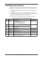
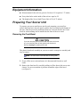
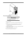
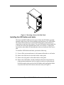
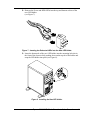
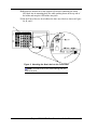
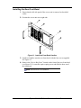
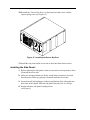
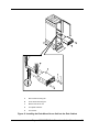
Express5800/120Ed
Rack Mount Kit
Installation Procedures
PN: 455-01607-001
Proprietary Notice and Liability Disclaimer
The information disclosed in this document, including all designs and related materials, is
the valuable property of NEC Computers Inc. and/or its licensors. NEC Computers Inc.
and/or its licensors, as appropriate, reserve all patent, copyright and other proprietary
rights to this document, including all design, manufacturing, reproduction, use, and sales
rights thereto, except to the extent said rights are expressly granted to others.
The NEC Computers Inc. product(s) discussed in this document are warranted in
accordance with the terms of the Warranty Statement accompanying each product.
However, actual performance of each such product is dependent upon factors such as
system configuration, customer data, and operator control. Since implementation by
customers of each product may vary, the suitability of specific product configurations and
applications must be determined by the customer and is not warranted by NEC Computers
Inc.
To allow for design and specification improvements, the information in this document is
subject to change at any time, without notice. Reproduction of this document or portions
thereof without prior written approval of NEC Computers Inc. is prohibited.
Trademarks
All products, brands, or trade names used in this publication are the trademarks or registered
trademarks of their respective trademark owners.
PN: 455-01607-001
February 2001
Copyright 2000, 2001
NEC Computers Inc.
15 Business Park Way
Sacramento, CA 95828
All Rights Reserved
Express5800/120Ed
Rack Mount Kit Installation Procedures
CONTENTS
Introduction ............................................................................................................................................3
Unpacking and Inspection ......................................................................................................................4
Before You Begin...................................................................................................................................6
What You Need ......................................................................................................................................6
Static Precautions ...................................................................................................................................6
Equipment Information...........................................................................................................................7
Preparing Your Server Unit ....................................................................................................................7
Removing the Front Bezel..................................................................................................................7
Removing the Side Panels..................................................................................................................8
Installing the LED Holder and Labels................................................................................................9
Removing a Foot Stand ....................................................................................................................13
Installing the New Front Bezel.........................................................................................................15
Installing the Side Panels .................................................................................................................18
Preparing the Mounting Bracket Assemblies ...................................................................................19
Attaching the Mounting Bracket Assembly to the Rack ..................................................................19
Installing the Server into the System Rack.......................................................................................21
Making Connections.............................................................................................................................23
Connecting the Power Cord..................................................................................................................24
Powering On Your System ...................................................................................................................25
Introduction
This guide provides you with assembly information for preparing and mounting
your Express5800/120Ed Server small tower unit into a system rack
(see Figure 1).
Figure 1. Rack Mounted Server Small Tower Unit
Express5800/120Ed Rack Mount installation Procedures 3
Unpacking and Inspection
Although the rack mount kit is inspected and carefully packaged at the factory,
damage may occur during shipping. Follow these steps for unpacking the kit.
1. Visually inspect the shipping container; notify your carrier immediately of
any damage.
2. Place shipping container on a flat, clean, stable surface. Carefully remove
and verify the contents (see Table 1 and Figure 2). If parts are missing or the
equipment is damaged, notify your server representative.
3. Save the container and packing materials for any future reshipment.
Table 1. Rack Mount Kit Parts List (NZA-1203-00-00)
Item
Name
Description
Part Number
A
Rail Kit
1U Rail Kit includes:
Left Mounting Rail (246-01521-000)
Right Mounting Rail (246-01522-000)
Packet of screws (250-0151-000)
246-01523-000
B
Front Bezel
Bezel assembly
890558
C
Plastic Bag
Plastic bag containing four screws and two bezel
assembly handles
D
LED Holder
LED holder
246-01530-000
E
Sleep Label
Sleep stick-on label
405-01580-000
F
Status Label
Status stick-on label
405-01579-000
G
Name Plate
Name plate logo stick-on label
405-01545-000
H
Document
Installation Guide for the 120Ed Server Small Tower
Rack Mount Kit (This manual)
455-01607-000
Express5800/120Ed Rack Mount installation Procedures 4
A
B
D
C
E
F
H
G
Express5800/120Ed
Figure 2. Rack Mount Kit Parts
Express5800/120Ed Rack Mount installation Procedures 5
Before You Begin
Before you begin, please review the following cautions, warnings, and general
guidelines.
! WARNING
Be sure that power to the server unit is turned off and
unplugged. All voltage is removed only when the power cord
is unplugged.
!
Avoid excessive vibration and shock. Dropping an electronic component can
cause serious damage.
!
Do not disconnect or remove parts other than those specified in the
procedure.
!
Do not touch I/O connector pins.
!
All screws are Phillips-head, unless otherwise specified.
!
On completion of any reassembly, perform a power-on test. If a fault occurs,
verify that the reassembly was performed correctly. If the problem persists,
see the Problem Solving chapter in your System User’s Guide.
What You Need
In addition to the carton contents, the only tools you need are a #2 Phillips,
adjustable crescent wrench, and a utility knife to assemble the server unit.
! CAUTION
It is strongly recommended that two people are present
when lifting and installing the server unit into a system rack.
Static Precautions
An electrostatic discharge (ESD) can damage disk drives, option boards, and
other components. You can provide some ESD protection by wearing an antistatic wrist strap attached to chassis ground when handling system components.
Electronic devices can be easily damaged by static electricity. To prevent
damage, keep them in their protective packaging when they are not installed in
your system.
Express5800/120Ed Rack Mount installation Procedures 6
Equipment Information
!
Measurements for the rack are given in Us where 1U is equal to 1.75 inches.
!
Every three holes on the inside of the rack are equal to 1U.
!
The height of the Server Small Tower Unit is 5Us (8.75 inches).
Preparing Your Server Unit
To prepare your server small tower unit for rack mounting, you must first
remove the front bezel, the side panels, and the four foot stands on the bottom of
the unit. After the previously mentioned items are removed, then the new front
bezel for rack mounting can be installed on the front of the server unit.
Removing the Front Bezel
! CAUTION
If you are removing the front bezel after the server unit is set
up, you must first power off the system and all external
devices. Unplug the system power cord
The plastic front bezel assembly on your server unit is a one-piece assembly and
easy to remove.
Note: The front bezel is secured with six locking tabs.
1. Power off the server unit and ensure it is disconnected from the ac wall
outlet.
2. Remove the front bezel by carefully pulling it off the front of the server unit
chassis. Use an even amount of pressure around the edges of the bezel.
(see Figure 3).
Express5800/120Ed Rack Mount installation Procedures 7
Figure 3. Removing the Front Bezel
Removing the Side Panels
! CAUTION
If you are removing a side panel after the server unit is set
up, you must first power off the system and all external
devices. Unplug the system power cord
To remove a side panel:
1. Power off the server unit and ensure it is disconnected from the ac wall
outlet.
2. The side panel is secured to the chassis with three screws. Remove the
screws (see Figure 4) securing the side panel. Save the screws for
reattaching the side panel.
3. Slide the side panel toward the rear of the chassis. This unlocks the locking
fingers behind the side panel.
4. Pull the side panel up and away from the chassis.
5. Remove both the right and left side panels.
Express5800/120Ed Rack Mount installation Procedures 8
Figure 4. Removing a Server Unit Side Panel
Installing the LED Holder and Labels
The Power and HDD LEDs must be removed from the LED holder currently
installed on the front of the chassis and then reinserted into a new LED holder.
The Status LED remains in its current LED holder and is reinserted into its
original slot in the front of the chassis. The new LED holder is then installed in
a vacant slot on the front right-hand side of the server chassis. A name plate
logo and two other labels are then adhered to the new front bezel of the server
unit.
To install the LED Holder and labels, perform the following:
1. Power off the system and ensure it is disconnected from the ac wall outlet.
2. Remove the front bezel as described earlier in this guide.
3. Remove the side panels as described earlier in this guide.
4. Remove the LED holder currently installed on the front of the chassis by
using a pointed instrument, such as a small screwdriver or ball-point pen.
Push downward on the top tab of the LED holder while pulling the holder
away from the front of the chassis at the same time (see Figure 5).
Express5800/120Ed Rack Mount installation Procedures 9
Figure 5. Removing the LED Holder Assembly
5. Tag and remove the Power and HDD LEDs from the top and bottom sockets
of the LED holder (see Figure 6).
Power
HDD
Figure 6. Removing LEDs from the LED Holder
6. Feed the Power and HDD LED cable assemblies back through the mounting
hole in the front of the chassis.
7. Reroute the power and HDD LEDs through hole on the right side of the
chassis, then into the new LED holder mounting hole slot located on the
front right-hand side of the chassis. See Figure 8.
Express5800/120Ed Rack Mount installation Procedures 10
8. Reinsert the Power and HDD LEDs into the top and bottom sockets of the
new LED holder
(see Figure 7).
Figure 7. Inserting the Relocated LEDs into the New LED Holder
9. Insert the bottom tab of the new LED holder into the mounting hole slot in
the front of the chassis while pushing down on the top tab of the holder and
snap the LED holder into place (see Figure 8).
Figure 8. Installing the New LED Holder
Express5800/120Ed Rack Mount installation Procedures 11
10. Reinsert the bottom tab of the original LED holder containing the Status
LED back into its mounting hole slot while pushing down on the top tab of
the holder and snap the LED holder into place.
11. On the front of the new bezel adhere the three new labels as shown in Figure
9A, B, and C.
A
Express5800/120Ed
B
C
Figure 9. Attaching the New Labels to the Front Bezel
Note: The Status LED is now viewed through the new
front bezel panel.
Express5800/120Ed Rack Mount installation Procedures 12
Removing a Foot Stand
Each of the four foot stands located on the bottom of the server unit consists of a
three piece assembly and are easily removed (see Figure 10).
Note: Each foot stand is secured with two small screws.
1. Power off the system and remove the left side panel of the server unit as
described earlier in this chapter.
2. Position the server unit on its right side.
3. Remove the two screws securing the foot stand to the bottom of the server
unit. The two screws are located inside on the bottom of the server unit.
Note: If an option card is installed in the bottom
expansion slot of the server unit, it may be necessary to
remove the option card, before the hex screw can be
removed that is located under the card.
4. Remove the foot stand (stationary base, movable stand, and long stem nut)
from the server unit.
5. Repeat steps 3 and 4 until all four foot stands are removed.
Express5800/120Ed Rack Mount installation Procedures 13
A
B
D
C
E
Bottom
Top
Figure 10. Removing a Foot Stand
Item
Description
A
Long Stem Nut
B
Movable Stand
C
Stationary Base
D
Hex Screw
E
Phillips Head Screw
Express5800/120Ed Rack Mount installation Procedures 14
Installing the New Front Bezel
1. Ensure that the left side panel of the server unit is removed as described
earlier.
2. Position the server unit on its right side.
Figure 11. Install the Front Bezel Handles
3. Install two handles onto the new front bezel with the four screws supplied.
See Figure 11.
4. Remove the “Device Bay Door” located on the front of the new front bezel
(see Figure 12). Loosen the captive spring screw and slide the door out of
the front bezel.
Note: Save the door for reinstallation.
Express5800/120Ed Rack Mount installation Procedures 15
Figure 12. Removing the Device Bay Door
5. Remove the three screws that secure three small brackets located at the top
of the new front bezel. See Figure 13. Save the screws and brackets for use
in Step 8.
6. Carefully tilt and insert the bottom tab hooks of the front bezel into the
corresponding bottom tab slots in the front of the server unit (see Figure 13).
If necessary, loosen the screws on the bottom screw brackets of the front
bezel so that the tab hooks can be easily aligned to go into the bottom tab
slots of the server unit.
! CAUTION
Be careful not to damage LEDs protruding out from the front
of the chassis
7. Pivot the top edge of the front bezel up towards the top edge of the server
unit until its top metal tabs protrude through the top tab slots.
8. Place a screw bracket over one of the top metal tabs with its back edge up
against the inside of the chassis and secure it with a screw. Repeat this step
for the other top metal tabs.
Express5800/120Ed Rack Mount installation Procedures 16
Figure 13. Installing and Securing the Front Bezel
9. Locate the three screw holes underneath the bottom of the front bezel and
loosen the screws (see Figure 14). Firmly hold the bottom of the bezel flush
against the bottom of the server chassis and tighten the screws. This will
correctly align the front bezel to the server chassis.
Figure 14. Aligning the Front Bezel to the Server Unit
Express5800/120Ed Rack Mount installation Procedures 17
10. Reinstall the “Device Bay Door” on the front bezel and secure with the
captive spring screw (see Figure 15).
Figure 15. Installing the Device Bay Door
11. Install the side panel on the server unit as described later in this section.
Installing the Side Panels
1. Before replacing the side panels, make sure no tools or loose parts have been
left inside the server unit.
2. Make sure all option boards are firmly seated in their respective slots and
that all interior cables are properly connected inside the server unit.
3. Insert the metal locking fingers on the top and bottom of the side panel into
their slots on the chassis. Slide the side panel forward as far as it will go.
4. Replace the three side panel retaining screws
(see Figure 4).
Express5800/120Ed Rack Mount installation Procedures 18
Preparing the Mounting Bracket Assemblies
Your server mounts in the system rack using two rail assemblies. The left rail
assembly as viewed from the front of the system rack is shown in Figure 16.
Each rail assembly consists of two rack mounting brackets (A and B). These
pieces can be separated and adjusted. The distance between the front rack
mounting bracket (A) and the rear rack mounting bracket (B) is adjustable to fit
between the front and rear vertical rails of the system rack.
B
A
Figure 16. Left Rail Assembly
1. Referring to Figure 16, remove any screws securing the front mounting
bracket (A) to the rear mounting bracket (B). Perform this step on the right
rail assembly.
2. Select an appropriate location in the rack cabinet for the rack-mount server.
To improve rack stability, mount heavier items towards the bottom of the
rack cabinet.
Note: When planning the server configuration for the
rack cabinet you should consider the length of the cables
that interconnect with system components.
Attaching the Mounting Bracket Assembly to the Rack
1. Attach the left side front mounting bracket to the front of the rack using two
Phillips flange head screws supplied. See Figure 17.
2. Attach the right side front mounting bracket to the front of the rack using
two Phillips flange head screws supplied.
Express5800/120Ed Rack Mount installation Procedures 19
Figure 17. Attaching the Mounting Bracket to the Front of the Rack
3. Attach the left and right rear mounting brackets to the rear of the rack using
Phillips flange head screws supplied.
4. Attach the left front and rear mounting brackets to each other using three of
the Phillips-head self-tapping screws and flat washers supplied.
See Figure 18.
Figure 18. Securing the Front and Rear Mounting Brackets
5. Attach the right front and rear mounting brackets to each other using three of
the Phillips-head self-tapping screws and flat washers supplied.
6. Securely tighten the all Phillips screws installed in steps 1 through 5.
Express5800/120Ed Rack Mount installation Procedures 20
Installing the Server into the System Rack
This section describes how to install your rack-mount server unit into a standard
EIA 19-inch rack cabinet.
! WARNING
Your system weighs approximately 45 pounds (20.41 kg). If
your system contains numerous optional boards and
peripheral devices, it will weigh more. To avoid personal
injury, make sure you have someone help you lift or move
the system.
! WARNING
Ensure that the location of the rack-mount server unit does
not create an unstable condition when installed in the rack
cabinet.
1. Lift the rack-mount server unit Figure 19, C onto the two support brackets
and slide it toward the rear of the rack cabinet.
! WARNING
It is strongly recommended that two people are present
when lifting and assembling the rack-mount server unit into a
rack cabinet.
2. Secure the front bezel to the rack cabinet's front vertical mounting rails (B)
using the four screws (E) and plastic washers (D) provided. See Figure 19.
Express5800/120Ed Rack Mount installation Procedures 21
A.
Rear vertical mounting rail
B.
Front vertical mounting rail
C
Rack-mount server unit
D
Four plastic washers
E
Four screws
Figure 19. Installing the Rack-Mount Server Unit into the Rack Cabinet
Express5800/120Ed Rack Mount installation Procedures 22
Making Connections
Refer to Figure 20 and connect your keyboard, monitor, and mouse. Connect
any external peripheral devices such as a printer or modem by following the
instructions included with these devices.
! CAUTION
Damage to the system may result if the keyboard/mouse
cable is inserted or removed when power is applied to the
system.
Inserting a telephone line connector into a LAN board RJ-45
port may result in personal injury and equipment damage.
1
2
Figure 20. Making Connections
Express5800/120Ed Rack Mount installation Procedures 23
Connecting the Power Cord
Plug the female end of the AC power cord into the input receptacle on the rear
of the power supply cage. Plug the male end of the power cord into NEMA 515R outlet for 100-120 VAC or NEMA 6-15R outlet for 200-240 VAC.
If the power cord supplied with the system is not compatible with the AC wall
outlet in your region, obtain a suitable power cord that meets the following
criteria.
!
The power cord must be rated for the available AC voltage and have a
current rating that is at least 125% of the current rating of the system.
!
The power cord connector that plugs into the wall outlet must be terminated
in a grounding-type male plug designed for use in your region. It must have
certification marks showing certification by an agency acceptable in your
region.
!
The power cord connector that plugs into the system must be an IEC- type
CEE-22 female connector.
!
The power cord must be less than 1.8 meters (6.0 feet) long.
When connecting the power cord to a power control unit such as an UPS,
confirm that the power control unit is powered off. Connecting the power cord
while power is supplied to the power control unit may cause a failure.
! WARNING
Your system shipped with a power cord for the power
supply. Do not attempt to modify or use the supplied AC
power cord if it is not the exact type required.
Express5800/120Ed Rack Mount installation Procedures 24
Powering On Your System
Power on your system as follows.
1. Make sure all external devices, such as a video display, keyboard, and
mouse have been connected, and the power cords are connected.
2. Power on the video display and any other external devices.
3. Press the push-button power on/off switch on the front panel. Verify that the
system power-on LED is lit.
Note: The server management logic on your system
board monitors and logs system voltage changes. When
powering up or down your system you may experience a
1–5 second delay from the time you press the push-button
power on/off switch on the front panel and your system
powering down. This is normal system operation and is
required by the server management logic.
After a few seconds your system begins the internal Power-On Self Tests
(POST). POST automatically checks the system board, CPU module, memory,
keyboard, and most installed peripheral devices.
! CAUTION
Always allow POST to complete before powering down your
system.
If you have problems powering on your system, refer to Problem Solving in
Chapter 5 of your System User’s Guide.
After you have successfully powered on your system, insert the
EXPRESSBUILDER CD-ROM into the CD-ROM device, reboot the system and
follow the screen prompts to run EXPRESSBUILDER.
Express5800/120Ed Rack Mount installation Procedures 25