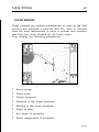
1
11C
10C
User and Installation Guide
Manuale d’uso e d’installazione
Manuel d’emploi et d’installation
11C
10C
User and Installation Guide
READ THIS WARNING BEFORE USING THE GEONAV
WARNING
THE ELECTRONIC CHART IS AN AID TO NAVIGATION DESIGNED TO FACILITATE THE USE OF AUTHORIZED GOVERNMENT CHARTS, NOT TO REPLACE THEM.
ONLY OFFICIAL GOVERNMENT CHARTS AND NOTICES
TO MARINERS CONTAIN ALL INFORMATION NEEDED FOR
THE SAFETY OF NAVIGATION AND, AS ALWAYS, THE
CAPTAIN IS RESPONSIBLE FOR THEIR PROPER USE.
The use of the GEONAV implies knowledge and acceptance of this warning by the user.
NOTE: Technical characteristics and functions described in this manual are subject to
change as a result of improvements or changes to the product.
This unit runs Linux, developed under GNU General Public License. Linux is a
registered trademark by Linus Torvalds.
Introduction
4
INTRODUCTION
The GEONAV is a chart plotter that can be interfaced with a
GPS receiver, autopilot and other onboard instruments, and
allows displaying the boat’s geographical position with respect
to an electronic chart. Thanks to the GEONAV and a
NAVIONICS Gold™ electronic chart, you will never get lost
even in case of fog, bad weather or dark.
The GEONAV has been designed to allow flush mounting.
Equipped with an easy-to-use keyboard, the GEONAV allows
controlling the autopilot directly from the plotter (Easy Pilot
function) and, thanks to the unlimited capacity of the
CompactFlash™ cartridges - that can also be used on PCs as
personal hard disks - can store a large amount of route, track
and marker data.
The GEONAV is ready for connection with the wind station
and echosounder and, thanks to windows enabled automatically, able to display the relevant data, if available. The connection supports both the NMEA 0183 standard protocol and
the Ethernet Connection system, suitable for the network connection of multiple stations.
The Route functions will allow you to plan a trip, while, thanks
to NAVIONICS Gold™ electronic charts, you will always know
exactly the boat’s position. NAVIONICS Gold™ charts are available for all the most popular boating areas, provide a large
amount of data - thanks to the object-oriented technology and can be used in addition to official paper charts to obtain
additional information such as the availability of port services,
as well as tides and currents data. NAVIONICS Gold™ electronic charts are available worldwide from authorized
NAVIONICS dealers.
Should new functions be available in the future, it will be
possible to update the GEONAV internal software at any
NAVIONICS dealer.
English
Characteristics
5
CHARACTERISTICS
General characteristics
• Easy Pilot function for easy and direct control of autopilot
• Possibility to transfer routes, tracks and markers from one
plotter station to another through network connection
• EBL and VRM functions
• Multiple display of tracks
• Storage of track data including significant additional information such as date, time, latitude/longitude, depth,
temperature, wind data, etc.
• GOTO function (Waypoint, Port, Nearest Service, Marker,
Track, Lat/Lon, R/B)
• Screen Amplifier™ function
• Autozoom™ function
• Overzoom™ function
• 8 marker shapes, 8-character name
• Reverse route function
• Selectable depth units (meters, feet and fathoms)
• Cartography with port services and Tides and Currents
data
• EasyView™ function
• X-plain™ function
• ARPA display function
• Heading vector
• Speed and heading filters
• CompactFlash™ cartridge
• Storage of routes, tracks and markers in separate files on
CompactFlash™ cartridges
• NMEA 0183 interface (ver. 2.03)
• Ethernet connection
• Display of depth and water temperature data (if interfaced
with an echosounder)
• Display of wind data (if interfaced with wind instruments)
• Backlit keypad
• Color LCD, transflective TFT 10.4”, daylight visible (G10C
model)
English
Characteristics
•
6
Color LCD, TFT 10.4”, enhanced contrast and brightness,
sunlight visible (G11C model)
Electrical characteristics
• Power supply: 9 to 36 Vd.c.
• Power consumption: Max. 13 W (G10C model)
• Power consumption: Max. 21 W (G11C model)
• Auxiliary voltage output: 10 to 36 Vd.c.
(same as input voltage) - Max. 250 mA
• Protection against:
Reverse polarity
Input overvoltage (up to 40 Vd.c.)
Overcurrent at auxiliary voltage output (over 250 mA)
• Operating temperature: 0°C to +55°C
• Storage temperature: -20°C to +70°C
Memory characteristics
• Up to 100 waypoints per route
• Up to 5000 trackpoints (multiple tracks)
• Up to 3000 markers per group
• Number of routes, tracks and markers: unlimited, depending on the size of the CompactFlash™ used
Interface characteristics
• Standard NMEA 0183 sentences
- from position sensor:
GLL, VTG, GGA, RMC, GSV, ZDA, RMA, GSA, GNS,
DTM
- from depth sounder:
DBT, MTW
- from ARPA:
TLL, TTM
- to autopilot:
APA, APB, XTE, RMB, BWC, GLL, VTG
If received from the GPS, the following sentences are transmitted:
GGA, RMC, ZDA.
English
7
Accessories
• Bracket for detachable installation
• Gasket and drilling template for panel mounting
• Plastic frame and drilling template for flush mounting
• Power supply cable
• Auxiliary power supply cable
• User and Installation Guide
• Protection cap
• Carrying case
English
Installation and Precautions
8
INSTALLATION AND PRECAUTIONS
Precautions
Wherever possible, the power supply cable shield should be
connected to the boat’s ground plate.
The GEONAV is water resistant but not waterproof, therefore
it should not be immersed totally in water.
The cartridge slot cover, located on the plotter’s right-hand
side, should always be kept closed and opened only when
replacing cartridges. Make sure that the cartridge replacement
is carried out as the unit is perfectly dry and that no water
enters the unit.
Rear connectors, when not in use, should always be protected
by the appropriate rubber covers.
Cleaning
It is recommended the use of a non-alcoholic product to clean
the glass, since alcoholic products may damage the glass surface or make it opaque.
Panel mounting
Locate the area where the GEONAV is to be installed, then
use the drilling template supplied with the plotter to properly
cut holes and sockets out of the instrument’s panel.
The neoprene adhesive gasket supplied must be applied to
the GEONAV rear side to avoid moisture penetration and to
reduce vibrations.
Mounting screws must be 4 mm in diameter and maximum 5
mm in length, plus the thickness of the panel. Do not exceed
tightening the screws, in order to avoid damaging the screw
seats.
English
9
Flush mounting
Locate the area where the GEONAV is to be installed, then
use the cutting template supplied with the plotter to cut the
panel.
Apply a layer of silicone glue (the use of black colored glue is
recommended, in order to prevent the area from going yellow
when exposed to sunlight) to the plastic frame rear part; place
the frame into the socket cut out of the panel, so that the
frame edge leans against the panel.
Make sure that the frame and the panel are correctly fixed; if
necessary, apply additional metal brackets (not supplied in
the package) as shown in the relevant figure.
Let the silicone glue dry, then apply the neoprene gasket to
the plotter rear side, insert the instrument into the frame and
lock it by the screws supplied.
Do not exceed tightening the screws, in order to avoid damaging the screw seats.
English
Installation and Precautions
Bracket mounting
Fix the bracket to the boat’s dashboard
by screws 6mm in diameter.
English
10
Connections
11
CONNECTIONS
Power supply and data connector (9 pins)
1. Power supply
1
+ VDC
2
GND
2. NMEA 0183 data input
3
GPS IN +
4
GPS IN 3. NMEA 0183 data output
5
DATA OUT +
6
DATA OUT 4. Auxiliary output voltage (Vaux)
7
Vaux+, 250mA *
8
GND
9
SHIELD
* Vaux voltage is the same as the plotter’s input voltage.
If sent by the position sensor, the following NMEA messages
are transmitted to external devices (e.g., autopilot):
APB - XTE - RMB - BWC - GLL - VTG
The GEONAV will add the following messages (if received
from the position sensor):
GGA - RMC - ZDA
Auxiliary connector (7 pins)
Allows connecting the GEONAV to an
auxiliary instrument equipped with
NMEA 0183 interface (e.g., echosounder
and mast head transducer).
1. NMEA 0183 auxiliary data input
1
DATA IN +
2
DATA IN English
Connections
Network connector (6 pins)
1. Ethernet connection
1
I AN GND 1
2
RX +
3
RX 4
I AN GND 2
5
TX +
6
TX -
English
12
Cartridge Installation
13
CARTRIDGE INSTALLATION
Installing the CompactFlash™
Open the cartridge slot cover located on the plotter’s front
side.
Insert the cartridge into the appropriate slot, with the label
side (side with a small arrow) towards the right, and push it
down.
Close the cover exercising light pressure and check that it is
perfectly closed, in order to avoid any water infiltration.
NOTE: Make sure of inserting the cartridge correctly. Should you try to insert the
wrong side of the cartridge, full insertion into the slot is hampered. Any further attempt
to force the cartridge into the slot may damage the cartridge or the plotter. This kind of
damage is not covered by the warranty.
English
Cartridge Installation
14
Removing the CompactFlash™
Make sure that the plotter is perfectly dry.
Open the cartridge slot cover located on the plotter’s front
side, then extract the cartridge.
WARNING: Always use CompactFlash™ cartridges certified by Navionics. The
use of non-certified cartridges may result in improper operation of the unit.
The CompactFlash™ cartridges can be used as a mass-storage
with any PC computer, so can be the cartridge used by the
plotter. However, the plotter needs to find some free space in
the cartridge in order to work properly. Prior to use a new
cartridge, always make sure that there are at least 2.5MB of
free space.
WARNING: Be careful when handling the cartridge files by using the PC. Windows
allows deleting and moving files easily, therefore pay attention when using Windows
Explorer not to erase the content of the \NAVIONIC and \GEONAV folders. Damaging
the files stored in such directories may result in loss of data or improper operation of
the unit.
English
Keyboard
15
KEYBOARD
ZOOM-/ZOOM+
• Increases/decreases
the chart scale
• Enables/disables the
Autozoom function
JOYSTICK (right/left - up/down)
• Moves
the
cursor
across the screen
• Switches from Navigation mode to Cursor
mode
• Selects the options
from
menus
and
submenus
If pressed:
• Displays the chart object attributes
ENT (ENTER):
Cursor mode:
• Inserts a waypoint at
the cursor’s position
• Inserts a marker at the
cursor’s position (if
held pressed)
Navigation mode:
• Changes the target
waypoint
Menu:
• Confirms a selection
English
Keyboard
16
GOTO
• Accesses the main menu
Plots a route to:
• A new target waypoint
• A marker
• A port
• The nearest port service
Positions the cursor on the coordinates selected (Lat/Lon or
Range/Bearing).
CLR
• Cancels the setting of data in the windows
• Cancels the option selection from the menu
Cursor mode:
• Deletes all waypoints, starting from the last entered
• Deletes the waypoint pointed by the cursor
• Deletes the marker pointed by the cursor
Navigation mode:
• Deletes the whole current route
KNOB
• Adjusts EBL/VRM parameters
• Selects the several options from the menu windows
• Scrolls letters and numbers when entering data in the
windows
If pressed:
Navigation mode:
• Switches from EBL to VRM
Menu:
• Switches from vertical to horizontal scrolling and confirms
the selection
EXIT
• Cancels a selection
English
17
Cursor mode:
• Switches from Cursor
mode to Navigation
mode
Navigation mode:
• Turns the pages of
navigation data
PWR
• Switches the GEONAV
on
• Opens the contrast/
brightness window
• Switches the GEONAV
off (if held pressed for
more than 3 seconds)
English
Diagnostic
18
DIAGNOSTIC
The GEONAV features a diagnostic program to verify its correct performance, once installed, and to detect problems that
may occur during the use of the unit.
To access the diagnostic program, keep pressed any key but
CLR, while pressing the PWR key.
The GEONAV will switch on and carry out automatically a
test of the whole system; as soon as the memory test is completed, the program will test the LCD, the CompactFlash™
card and the keyboard. Press ENTER to run one test, CLR to skip
to the next one. To exit from the keyboard test, press CLR
twice.
Once the keyboard test is completed, the diagnostic program
allows checking the messages received from the GPS through
the NMEA 0183 port. Hold the knob pressed to freeze the
messages on the screen, then release it to keep on displaying
the new messages sent by the GPS. To test channel 1 (depth
sounder or wind instrument), press GOTO. Press CLR to quit.
After the keyboard, the diagnostic program will test the internal non-volatile memory and the backlight. Press ENTER to run
one test, CLR to skip to the next one.
Once terminated all tests, press ENTER to re-boot the unit.
WARNING: The internal memory can be cleared by pressing simultaneously the
PWR and CLR keys. This operation will delete all the settings stored in the GEONAV
and restore factory settings.
NOTE: In case of damaged cartridge or abnormal power spikes, the unit might lock,
requiring a power shutdown to restart. In that case, the unit can be turned off without
the need of detaching the power, by simply holding the PWR key pressed for more
than 10 seconds. This function is useful if the unit is panel mounted or flush mounted
and the power switch cannot be easily accessed.
English
NAVIONICS Electronic Charts
19
NAVIONICS ELECTRONIC CHARTS
The GEONAV includes a built-in world map. Additional cartography details relative to a specific area of navigation are
available from the CompactFlash™ cartridges storing
NAVIONICS Gold™ electronic charts.
NAVIONICS
electronic
charts contain a detailed set
of symbols, similar to those
used on official nautical
charts.
To display chart boundaries, press the GOTO key to
display the menu, select
SETUP/DISPLAY,
then
CHART BOUNDARIES and,
by the joystick, select ON/
OFF to enable/disable the
boundaries of the charts
stored in the cartridge.
A small square will locate the area covered by the cartridge
installed; position the cursor within the square and then decrease the chart scale by the ZOOM+ key to display the details
of the area covered by the cartridge.
The maximum detail level is obtained within port plans where
the smallest point on screen can be equivalent to approximately 1 meter, depending on the cartridge type and coverage.
Increasing/decreasing the chart scale
Press the -ZOOM+ key. The current chart scale is shown by a
small segment in the lower right-hand corner of the screen.
Chart scales can range from 512 NM down to 40 ft in Overzoom
mode.
English
NAVIONICS Electronic Charts
20
Converting depth values into the units
set
Press GOTO to display the menu,
select SETUP/GENERAL, DEPTH
UNITS and then set the unit desired in meters, feet or fathoms.
The GEONAV will convert all the
depth values in the unit selected,
making them appear like those reported in the official nautical
charts (see the figure).
Displaying abbreviated navaid characteristics
Position the manual cursor on the navaid symbol. A window
will show the abbreviated characteristics relative to the navaid
selected.
Description of navaid characteristics:
ABBREVIATIONS FOR LIGHT
AL
alternating
F
fixed
FLL
fixed and flashing
FL (...)
group flashing
FL
single flashing
IQ
interrupted quick
OC
single-occulting
OC (...)
composite group occulting
Q
continuous group
ABBREVIATIONS FOR COLOUR
AM
amber
B
black
BL
blue
G
green
OR
orange
R
red
VL
violet
W
white
Y
yellow
ABBREVIATION FOR PERIOD
..S
xx seconds
ABBREVIATION FOR RANGE
..M
xx nautical miles
Displaying object attributes
Move the manual cursor on top of an object on the chart, then
press the joystick. A window will show the description of all
the objects present on the chart at the cursor’s position. Se-
English
21
lect one object from this window and press the joystick to
show all of the object attributes.
The objects that can be queried include depth contours, depth
areas, point objects (lights, navaids, landmarks, etc.), land areas, spot soundings, coastlines, rocks, wrecks and, in general, any symbol present on the chart.
By querying the lights and navaids, the X-plain™ function
will give the description of the object in natural language,
thus avoiding the use of abbreviations and symbols difficult to
understand.
Chart presentation mode
The symbols used to represent the objects on the chart (buoys,
lights, landmarks, etc.), as well as chart colors, can be selected between paper-chart International or US styles.
English
NAVIONICS Electronic Charts
22
Press GOTO to display the menu, select SETUP/DISPLAY, then
PRESENTATION (INTER. or US).
Depth contours
This function allows the user to select the display of depth
contours; the options available are:
OFF:
no depth contour displayed
5m:
display of contours only with depths up to 5 meters
10m:
display of contours only with depths up to 10 meters
20m:
display of contours only with depths up to 20 meters
ALL:
all depth contours displayed
Safety contours
This function allows the user to display the depth areas corresponding to the safety contour desired. The options available are:
OFF:
no depth area displayed
2m:
areas with depths up to 2 meters in dark blue
5m:
areas with depths up to 2 meters in dark blue, up to
5 meters in blue
10m:
areas with depths up to 5 meters in dark blue, up to
10 meters in blue
20m:
areas with depths up to 10 meters in dark blue, up to
20 meters in blue
The areas whose depths are over the limit set, and therefore
navigable under safety conditions, will be displayed in white.
Dryline areas are always displayed in green.
NOTE: The mentioned colors are those used in the DAY mode. In NIGHT mode, the
areas with depths over the limit set, and therefore navigable under safety conditions,
are in black, whereas the colors below the limit are dark blue for higher depths and
blue for lower depths (e.g. 5m: areas with depths up to 2m displayed in blue, up to
5m in dark blue).
Displaying chart details
The display of spot soundings, landmarks and other chart
English
23
details can be selectively enabled or disabled from the SETUP/
DISPLAY/CHART DETAILS menu.
Displaying light sectors
The display of light sectors can be enabled or disabled from
the Setup menu.
Press GOTO to display the menu, select SETUP/DISPLAY, then
LIGHT SECTORS (AUTO/ON/OFF).
Displaying port services
NOTE: This function is available only with the NAVIONICS cartridges containing the
Port Services feature.
Position the cursor on the port icon
and press ENTER.
A window will show the list of the port services available in
the port selected. Choose the service desired by the joystick.
The number and the type of icon differ from one port to another.
English
NAVIONICS Electronic Charts
24
Port services are identified by the following icons:
Health and first aid
services
Customer services
Information
and port
authorities
Tourist services and
shops
Water
Tide station
Engine, boat,
electronic and
other repairs
Fuel
Current station
The number and the type of service available will depend on
the cartridge installed.
Displaying Tides and Currents data
NOTE: This function is available only with the NAVIONICS cartridges containing
Tides and Currents data.
Position the cursor on the icon of a Tide or Current station, then press ENTER.
A graph will show the tide rate or the tidal stream relevant to
the station selected, as measured during the current day.
English
25
English
Graphic Items
26
GRAPHIC ITEMS
Besides chart data, the GEONAV displays some graphic items
useful during navigation.
The figure below shows some of these items.
1 - Marker
Indicates a point of interest associated with a symbol, a name
and a color.
2 - Track segment
Recording of the track actually
followed by the boat; the track is
displayed as a colored dashed
line.
3 - Boat’s position
Boat’s position according to the
data received from the GPS receiver.
4 - Rubber band
Line joining the last waypoint entered to the manual cursor,
or the boat’s position to the manual cursor when no waypoint
has been entered.
To delete this band, press the EXIT key and switch to Navigation mode.
5 - Route leg
Part of route between two waypoints.
6 - Waypoint
Waypoints are identified by a circle and a number. The route
starting point is marked by the “X” symbol. The target waypoint
is identified by a filled circle, whereas the route leg currently
followed is identified by a thicker line.
English
27
7 - Cursor
Indicates the position expressed in geographical coordinates
(latitude and longitude).
It is displayed when the plotter is in Cursor mode.
8 - Heading vector
Indicates graphically the boat’s current route.
9 – North indicator
Indicates the north direction when the Chart rotation function is enabled.
10 – True wind vector
Indicates the direction of true wind detected by onboard instruments.
11 – Layline
Indicates the direction after the next tack or gybe. In order to
achieve the best performance, the tack or gybe should be carried out as soon as the layline crosses the target waypoint.
English
Functional Characteristics
28
FUNCTIONAL CHARACTERISTICS
This chapter describes some of the most important functions
of the GEONAV, as well as the terms most commonly used in
this document.
Switching on/Switching off the unit
To switch the GEONAV on, press the PWR key. To switch it
off, keep the PWR key pressed for more than 3 seconds.
Welcome page
At start-up, the GEONAV displays a welcome page whose text
(e.g., the boat’s name) can be edited by the Setup menu (see the
Setup Section). To freeze the page displayed, press ENTER. To
unfreeze the page and continue with the instrument’s operation, press ENTER again.
Depth sounder
If connected to a depth sounder via NMEA, the GEONAV will
enable the depth sounder mode, showing a graph of the sea
bed or the relevant data in numerical form.
The depth value can be expressed in meters (default value),
feet or fathoms; to select the unit, press GOTO, then choose
SETUP/GENERAL and DEPTH UNITS (M/FT/FA).
Sailing functions
If connected to a mast head transducer (anemometer), the
GEONAV will automatically enable the Sailing mode, once the
wind speed and direction data have been received, and provided that the Sailing window is enabled via the Setup menu.
Navigation mode (automatic)
At start-up, the GEONAV automatically enables the Navigation
mode, as soon as the GPS transmits a valid fix; when in Navigation mode:
• The manual cursor is not displayed
• The depth sounder window can be accessed
English
29
This mode is also called automatic because the unit automatically updates the boat’s position on the screen.
Cursor mode (manual)
When in Cursor mode, the manual cursor is displayed. It is
possible to insert, delete and move waypoints, insert and delete
markers, display navaid information, etc., but it is not possible
to gain access to the depth sounder window.
To switch from Navigation mode to Cursor mode, use the
joystick. To go back to Navigation mode, press the EXIT key.
Chart rotation
Charts are traditionally displayed in north-up mode. This,
however, does not correspond to reality. For example, when
traveling southwards, the chart shows, on the right side of
the boat, what is actually located on the left side, and vice
versa.
Without Chart Rotation
With Chart Rotation
The Chart Rotation function allows rotating the electronic chart
displayed according to the plotted route (COG - Course Over
English
Functional Characteristics
30
Ground), as detected by the GPS receiver. Since the COG value
varies continuously, a filter has been inserted to prevent the
chart from bouncing.
The Chart Rotation function is enabled at a speed greater than
1 knot. To enable the Chart Rotation function, press GOTO,
select SETUP/DISPLAY, then CHART ROTATION and ON. A
message will prompt the user to select the chart scale before
activating the chart rotation. Confirm by pressing ENTER.
The northern direction will be indicated by the symbol
Autozoom
With the Autozoom function the GEONAV will always display
automatically the boat’s position and the target waypoint at
the best available chart scale. This function is enabled provided that at least one waypoint has been previously entered.
To enable the Autozoom function, press ZOOM+ until the
“AUTOZOOM ? ENTER = YES” message is displayed, then
confirm by pressing ENTER. To disable the Autozoom function,
press ZOOM.
When the GEONAV is turned on, and if at least one waypoint
has been previously entered, the Autozoom function will be
automatically enabled.
Screen Amplifier
This function automatically redraws the chart according to
the boat’s course, so as to maintain 2/3rds of the screen ahead
English
31
of the boat, provided that the boat’s speed is greater than 3
knots. This function will be enabled provided that no waypoint
has been previously entered.
EBL/VRM functions
The EBL (Electronic Bearing Line) and VRM (Variable Range
Marker) functions allow entering markers and waypoints as
range and bearing coordinates with respect to the current position.
To enable these functions, rotate the knob to display the EBL,
position the line on the bearing desired, then press the knob
English
Functional Characteristics
32
to enable the VRM ring and adjust its size by rotating the knob
so as to reach the range desired. To edit the values set, press
the knob to switch from the VRM function to the EBL function.
To insert a waypoint where the EBL and VRM intersect, press
ENTER; to insert a marker, hold ENTER pressed.
Range and bearing values are displayed in the lower righthand side of the screen, together with the indication of the
function currently enabled.
Press CLR to disable the two functions in sequence.
The VRM ring can also be used to set the range for navigation
from the coast, for example to avoid navigating out of the limit
allowed. In this case, set the EBL to any value, adjust the
VRM ring size as desired, then navigate making sure that at
least one point in the ring is always touching the coast.
Easy Pilot function
The Easy Pilot function allows editing temporarily a route set and followed by the autopilot,
but keeping the route unchanged. This function is useful to make corrections at once (e.g.,
because of other boats or to approach points of
interests), without having to edit the route
planned or disable the autopilot.
To enable this function, rotate the knob and
position the EBL on the new route to follow,
then press ENTER. The EBL will change color,
as the boat starts following the new route; the
planned route will be abandoned, although displayed. To go back to the planned route, thus
canceling the temporary correction, press CLR.
NOTE: The Easy Pilot function can be enabled only if a route is present.
English
33
Overzoom
The Overzoom function allows expanding the chart range.
The Overzoom does not provide any additional chart detail,
only improves the readability of the available information, acting as a magnifying glass.
When the Overzoom is enabled, the unit will add OVZ to the
scale displayed in the Navigation window.
To enable/disable the Overzoom function, press GOTO to display the menu bar, then select SETUP/DISPLAY, OVERZOOM
and ON/OFF.
Position calibration
All position sensors are affected by intrinsic errors that make
the boat’s position incorrect (from few meters to several hundred meters).
The position calibration function allows correcting manually
the position error present in all GPS, provided that this error
is not greater than 2 nautical miles.
Press GOTO and then, by using the joystick, select SETUP/
NAVIGATION, CALIBRATION and then ON. A message will
prompt the user to move the cursor to the boat’s true position,
appropriately enlarged by the ZOOM+ key.
Press ENTER to move the GPS boat’s position to the point indicated by the cursor. This operation will save the calibration
for use in future calculations.
NOTE: When the calibration is enabled, the coordinates (latitude/longitude) in the
General Info window will be marked by (*).
To cancel the calibration, press GOTO, select SETUP/NAVIGATION, CALIBRATION and then OFF.
Local time
This function allows entering local time instead of the Greenwich time (GMT) supplied by the GPS receiver.
English
Functional Characteristics
34
To enter local time, press GOTO and then, by using the joystick, select SETUP/NAVIGATION, SET TIME and then LOCAL.
The joystick will allow entering local time as well as confirming and saving the operation. To cancel local time, press GOTO,
select SETUP/NAVIGATION, SET TIME and then GMT.
Contrast/Brightness
Press the PWR key to display the CONTRAST/LIGHT window.
Use the joystick to switch from one option to the other and to
adjust the contrast/brightness level.
Press ENTER to exit.
Color
Besides displaying color nautical charts, the GEONAV allows
selecting the track and marker colors.
Press the GOTO key to access the menu, select TRACK or
MARKER, then COLORS and confirm by pressing ENTER; choose
the color desired and confirm the selection.
The color of markers can also be selected when entered or
edited, whereas the track segment color can be selected by
positioning the manual cursor on the segment itself.
The color of chart items can be chosen from DAY, NIGHT or
BRIGHT. Press GOTO to display the menu, select SETUP/DISPLAY, MODE and then DAY, NIGHT or BRIGHT.
Anchor alarm
This function allows generating an anchor alarm message that
warns the user when the ship moves farther than the selected distance from its anchoring position, that is the ship’s
position when the alarm is enabled. The reference distance
value for the alarm can also be set. After the alarm is issued,
press any key to reset it by using the current ship’s position
as the new anchor position. To set this function, press GOTO,
select SETUP/NAVIGATION and then ANCHOR ALARM.
English
35
ARPA
Your GEONAV allows displaying the position of targets tracked
by any radar featuring the ARPA (Automatic Radar Plotting
Aid) or MARPA (Mini-ARPA) function.
To activate the ARPA display function select ACTIVATE from
the GOTO/SETUP/ARPA menu. When the ARPA display function is active, the instrument shows the target data received
from the ARPA radar connected to the plotter through the
NMEA0183 port.
ARPA target representation
The figure below shows a sample of tracked ARPA targets.
The following graphic items are displayed:
1 - Target name
The name of the target being tracked.
English
Functional Characteristics
36
2 - Vector
Shows the current direction of the target. The longer the vector, the faster the target.
3 - Marks
Each mark provides the forecasted position of the target - based
on its own current speed and direction - every minute.
4 - Thicker mark
The last mark - thicker than the others - shows the forecasted
position of the target - based on its own current speed and
direction - after six minutes.
5 - Target shape
The target shape provides information on the target tracking
status. The status can be:
- Target being tracked (still in process of acquisition)
- Target being tracked (steady, i.e., currently tracked ok)
- CPA/TCPA warning: target falls within the CPA/TCPA limits
- Target lost
English
37
NOTE: When the ARPA function is active, the own ship vector shows the six marks
- like the target vectors - providing the forecasted position of the own ship every
minute for the next six minutes.
ARPA target information
To display the information concerning any ARPA target, move
the cursor on the target icon and press ENTER.
A window containing the information on the target will show.
CPA/TCPA limits
Press the GOTO key, select SETUP, then ARPA. Choose the
SET CPA/TCPA LIM. option to set the CPA (Closest Point of
Approach) and TCPA (Time to Closest Point of Approach) limits.
As soon as the CPA or TCPA parameters of a target become
lower than the selected limits, a warning message is issued.
Radar offset
Press the GOTO key, select SETUP, then ARPA. Choose the
English
Functional Characteristics
38
OFFSET GPS RADAR option to recall the menu that will allow
setting the position of the radar antenna with respect to the
GPS antenna, so as to improve the accuracy of target representation.
English
Quick Tour
39
QUICK TOUR
We recommend that you use the GEONAV intuitively, since
no damage will be caused by pressing an incorrect button.
Make sure that the
GPS receiver is connected, insert a
Compact Flash™
cartridge and press
the PWR key. At
start-up, the last
chart used will be
loaded by default.
If the chart is not found, the list of NAVIONICS charts stored
into the Compact Flash™ cartridge will be displayed. Select
the desired chart by the joystick, then confirm by pressing
ENTER. A message will warn the user that electronic nautical
charts do not replace official government charts.
Press the PWR key to turn the display backlight on and adjust
the brightness by the joystick; press ENTER to continue (enabling the Geonav mode).
The Satellite window will show the configuration of the satellites in use. As soon as the GPS receiver has obtained a
valid fix (it can take a few minutes), the boat’s position and
the relevant area will be displayed at the best scale available.
The default language is English. To change the language, press
GOTO to display the menu, then select SETUP/GENERAL, LANGUAGE and the desired language by the joystick.
The line, or vector, starting from the boat indicates the boat’s
direction, to be ignored if the boat is stationary.
Windows will display the boat’s speed, route, chart scale and
local time.
English
Quick Tour
40
The GEONAV is in Navigation mode; by the joystick, it is
possible to switch to Cursor mode (editing mode). The cursor
position is shown by two windows. The joystick allows moving in all directions.
To plot a route starting from the boat’s position, move the cursor to the position desired and press ENTER to insert a waypoint,
that will be indicated by a circle containing the number 1.
The windows will also show the time to reach the target
waypoint, distance, bearing and estimated time to arrive.
Press the EXIT key to go back to Navigation mode.
To add more waypoints, enter the Cursor mode by using the
joystick and repeat the operations described above.
As new waypoints are added, the numbering will increase
progressively. In case of error, waypoints can be deleted by
pressing the CLR key (Cursor mode), starting from the last entered. To go back to Navigation mode, press EXIT.
English
41
If an autopilot is connected to the GEONAV, the plotted route
is automatically followed as soon as the Navigation mode is
enabled.
NOTE: The cursor can be moved to the desired position by using the GOTO functions
as well. See the GOTO Section for more details.
The NAVIONICS Gold™ charts provide detailed information
that can be displayed at any time.
By using the joystick, position the cursor on the chart item
desired (symbol for light, buoy, depth area, etc.) and then press
the joystick; the information relative to the items situated in
that given position will be shown.
Use the joystick to scroll the information list, then press EXIT
to exit and select another item. Press EXIT again to go back to
Navigation mode.
English
Operating Modes
42
OPERATING MODES
When switching on the GEONAV, the user can select one of
the two main operating modes available.
Press the PWR key and wait for the message on official nautical charts to show (if required, select one chart among those
contained in the cartridge), then press EXIT to enable the STD
mode, or ENTER to enable the standard GEONAV mode. It is
also possible to press GOTO to enter the demo mode, in which
the unit automatically shows, in sequence, different views
relative to the chart currently loaded.
STD mode
This mode allows displaying the chart data according to the
RTCM standard. During navigation, only the ship’s position,
the heading vector and a set of chart items - defined by the
applicable regulations (and known as standard display) - are
displayed at full screen. Markers are not displayed and navigation data are made accessible only by quitting the standard
display. By enabling the manual cursor by the joystick, the
markers will show again, on condition that the relevant option on the Setup menu (DISPLAY/MARKERS ON/OFF) has
been selected.
Geonav mode
This is the unit standard mode. During navigation, the windows showing position and route (if present) data, as well as
the waypoints and markers, are enabled.
It is not possible to disable the marker display, whose relevant option does not appear in the Setup menu.
In Geonav mode, the unit displays different types of data,
according to the operating mode enabled (Cursor mode or Navigation mode). The following paragraphs will describe the differences between the modes available.
English
43
CURSOR MODE
To plan a new route, or to append waypoints to the existing
route, move the cursor by using the joystick and press ENTER.
The GEONAV will display the following data:
• Route overall length
• Time to the end of the route (estimated on the speed value
manually entered in the ROUTE menu; see the Route Section)
• Distance from the last waypoint to the cursor
• Chart scale
To edit the existing route, move the cursor by using the joystick. The GEONAV will display the following data:
• Distance from the boat’s position to the cursor
• Time to arrive to the cursor
• Bearing from the boat’s position to the cursor
• Chart scale
Now it will be possible to move the cursor on a route item to
edit it, or press ENTER to lengthen the route by appending new
waypoints.
English
Operating Modes
44
NAVIGATION MODE
By pressing the EXIT key repeatedly, it will be possible to access the several windows available, provided that they have
been previously enabled by the appropriate option of the Setup
menu.
When the fix is valid and no route is present, the window
sequence is the following:
NAVIGATION > DEPTH SOUNDER > TRIP > SATELLITE > GENERAL
INFO > TIDE INFO > RUNWAY
When a route is present, the window sequence changes as
follows:
SAILING > NAVIGATION > DEPTH SOUNDER > TRIP > SATELLITE >
GENERAL INFO > TIDE INFO > RUNWAY
The Depth Sounder window is displayed provided that data is
received from a depth sounder.
If data is received from the wind instrument, an arrow on the
ship’s position will indicate the true wind direction and, if a
route is present, the Sailing windows will be displayed.
The Tide Info window is displayed provided that a NAVIONICS
cartridge featuring Tides and Currents data is active (see the
Tide Info Window Section).
CHART ONLY MODE
To hide the Navigation windows and display a full screen
chart, press GOTO and EXIT at the same time.
Press any key to show the windows again.
English
Navigation Windows
45
NAVIGATION WINDOWS
These windows are automatically enabled as soon as the GPS
receiver has obtained a valid fix (FIX OK).
If no route has been entered, the following data will be shown:
•
•
•
•
•
•
Boat’s speed
Chart scale
Course
Sea depth (if available)
Water temperature (if available)
Local time
To change the chart scale, press the -ZOOM+ key.
English
Navigation Windows
46
If a route has been entered, the Navigation window will show
the following data:
•
•
•
•
•
•
•
•
Boat’s speed
Chart scale
Target waypoint
Distance to the target waypoint
Time to arrive to the target waypoint
Estimated time to the route end
Sea depth (if available)
Water temperature (if available)
NOTE: To display sea depth and temperature values, the GEONAV must be interfaced with a depth sounder.
English
Sailing Windows
47
SAILING WINDOWS
These windows are enabled automatically as soon as the GPS
receiver has obtained a valid fix (FIX OK), data is received
from the wind instruments, a route is present and provided
that they have been enabled via the Setup menu.
They display the following information:
•
•
•
•
•
•
•
•
Boat’s speed
Chart scale
Target waypoint
Distance to the target waypoint
Bearing to the target waypoint
Angle to steer
Sea depth (if available)
Water temperature (if available)
English
Sailing Windows
•
•
48
True wind speed
True wind direction (magnetic)
If more waypoints are present, besides the target waypoint, a
window will show the apparent wind data on the next leg.
The apparent wind speed is indicated by the digits in the
center of the window. The wind direction is represented
graphically by an arrow.
If a close hauled or a run is planned on the next leg, the
arrow will indicate the direction of apparent wind on the first
beat of the next leg, whilst the direction of apparent wind on
the waypoint will be represented by a single line. The bearing
to the following waypoint is also shown.
English
Depth Sounder Window
49
DEPTH SOUNDER WINDOW
This window, displayed if the GEONAV is interfaced with a
depth sounder, replaces the number indicating the sea depth
in the Motor Boating windows with a graph showing the sea
bed. If received, the graph shows the water temperature as
well.
When navigating in waters deeper than sounder operating
range or if the boat’s speed is too high for depth sounding,
data acquisition will be interrupted and the number replaced
by “—”.
English
Trip Window
50
TRIP WINDOW
The Trip window shows general data relating to the route
followed.
•
•
•
•
•
Average speed from departure
Maximum speed from departure
Time elapsed from departure
Partial distance covered from departure
Overall distance covered
To reset all counters (except for the overall distance) before
starting a new journey, press the CLR key.
English
Satellite Window
51
SATELLITE WINDOW
At start-up the satellite window displays
how many and which
satellites are tracked
by the GPS receiver.
The outer circle represents the horizon,
the inner one identifies a 45° elevation
with respect to the
horizon, and the central circle points to
the zenith.
The small squares
with numbers show
the satellites available.
As soon as a satellite is tracked by the GPS receiver, the number inside the square is displayed in reverse. The bars displayed on the left identify the signal quality; the longer the
bar, the higher the signal quality.
On the left of each bar, two digits indicate numerically the
signal/noise ratio.
Additional information:
•
Day, month, year, local or Greenwich time (at the first
start-up the GEONAV is initialized to Greenwich Time).
•
Boat’s position (lat/lon) (or the latest valid fix if the GPS
receiver is still searching for satellites).
•
•
Data on the current satellite situation (number and fix).
SOG, COG and altitude.
English
Satellite Window
52
The latitude and longitude values relevant to the boat’s position are displayed as soon as three satellites are tracked and a
2D fix (two dimensions) is available.
The altitude value is available only if four satellites are tracked
and a 3D fix is obtained.
As soon as a valid fix is available, the GEONAV will automatically switch to Navigation mode and display the boat’s position at the best chart range available; the window at the bottom of the screen will indicate the boat’s course and speed.
To recall the Satellite window, press the EXIT key repeatedly
until it appears.
English
General Info Window
53
GENERAL INFO WINDOW
This window displays the following information on the boat’s
current position:
•
•
•
•
•
Geographical coordinates
(latitude/longitude)
The position correction applied to the latitude and longitude (SETUP/NAVIGATION, CALIBRATION option)
Magnetic variation value received by the GPS
Course (COG)
Speed (SOG)
NOTE: This window is available in Navigation mode only.
English
Tide Info Window
54
TIDE INFO WINDOW
When a NAVIONICS cartridge featuring Tides and Currents
data is present, this window displays further information,
besides the forecast data supplied by selecting the Tides and
Currents station.
The following data is displayed:
•
•
•
•
•
•
•
Latitude and longitude at the
current boat’s position
Current time and date
Value of magnetic variation
received by the GPS
Dawn and sunset time
Moonrise and moonset time
Moon phase
Graph of estimated tide level
with respect to the current
position
WARNING: Unlike the graph displayed at a T&C station position (accessible through
the GOTO function, or by positioning the cursor on the Tides and Currents station
symbol) that is accurate since it is supplied by hydrographic offices, this graph
shows estimated data, being the result of interpolation between the two Tides and
Currents stations nearest to the point of interest. The accuracy of the estimate may
vary, depending on the coast type, the distance to the nearest stations, and other
geographical features.
English
Runway Window
55
RUNWAY WINDOW
This window displays the following information on the target waypoint:
•
•
•
•
•
•
•
•
Name of the target waypoint
Distance from the target
waypoint
Estimated time of arrival to
the target waypoint
Bearing
Course
Steering angle
XTD (right/left distance
from the planned route)
XTD limit (runway width)
The graph shows the boat’s position with respect to the route.
When the XTD reaches the extreme value shown in the lower
right-hand corner of the window, the boat symbol will reach
the runway right or left side.
To change the XTD limit, see the Setup Section.
NOTE: This window is available in Navigation mode only.
English
Main Menu
56
MAIN MENU
The main menu bar, that appears when pressing the GOTO
key, allows accessing the following options:
ROUTE: To display route information, reverse and delete the
route, set the consumption data and save or read data from the
cartridge.
TRACK: To enable/disable the track function, delete a track,
choose the track color, show the used percentage of track
memory and save or read data from the cartridge.
MARKER: To delete markers, choose the marker color, show
the number of markers used and available, and save or read
marker data from the cartridge.
GOTO PORT: To plan a route to a selected port.
GOTO NEAREST: To plan a route to the nearest port service.
SETUP: To enable/disable and change the plotter’s setup.
GOTO LAT/LON: To plan a route to a known geographical position.
GOTO RANGE/BEARING: To plan a route to a position whose range
and bearing values are known.
NOTE: The majority of menu items, once selected, show a series of submenus. Use
the joystick to move from one menu to another and press ENTER to choose one item.
English
Route
57
ROUTE
EDITING A ROUTE (CURSOR MODE)
Creating a waypoint
Using the joystick, move the cursor on the position desired
and press ENTER to insert a waypoint.
To enter further waypoints, move the cursor and press ENTER.
The new waypoint will be appended to the existing route.
Up to 99 waypoints per route can be entered, also by using the
GOTO functions available from the main menu.
Deleting the last waypoint
Press CLR. If the last waypoint is out of screen, the “DELETE
WP? ENTER = YES” message will be displayed.
Press ENTER to confirm the deletion.
Deleting a waypoint
Use the joystick to position the cursor on the waypoint to
delete and press the CLR key.
Deleting all waypoints in a route
Press the CLR key repeatedly until the “NO WP PRESENT”
message is displayed.
Moving a waypoint
Position the cursor exactly on the waypoint to move; press
ENTER to capture the waypoint, then move the waypoint to the
position desired and confirm the operation by pressing ENTER.
Inserting a new waypoint in a route
Position the cursor exactly on the route leg to edit and press
ENTER to capture the leg.
Once captured, the leg will show a thicker line to distinguish
it more easily from the other route legs. A window will also
show the leg captured and its length.
Move the manual cursor to the position desired, insert the
new waypoint and confirm by pressing ENTER.
English
Route
58
EDITING A ROUTE (NAVIGATION MODE)
If the manual cursor is displayed, press the EXIT key to enter
Navigation mode.
Changing the target waypoint
Use the “Route to a waypoint” function (see the Functions in
the Route Menu Section).
WARNING: The route will be modified and the new target waypoint selected will be
the first waypoint in the route.
Deleting all waypoints
Press the CLR key to show the “DELETE ROUTE? ENTER =
YES” message. Press the ENTER key to confirm the deletion or
another key to exit.
FUNCTIONS IN THE ROUTE MENU
Route Info
Route information is displayed on several adjacent pages containing general route information and the geographical coordinates of all waypoints. Press GOTO to display the main menu,
then select ROUTE. A window will show the following information:
English
59
WP NAME : Waypoint name
DISTANCE: Distance from START to current waypoint
TIME: Estimated time from START to current waypoint
FUEL LITERS: Estimated fuel consumption (liters or gallons)
BRG: Bearing from previous waypoint to current waypoint
POSITION: Waypoint latitude / longitude
The time to arrive to the waypoint and fuel consumption are
displayed provided that estimated speed and fuel consumption values have been entered (see the Entering speed and fuel
consumption data Section).
To move within the page and scroll the adjacent pages, use
the joystick. To go back to the menu, use the joystick; to exit,
press the EXIT key.
Entering speed and fuel consumption data
The data are used to calculate the values displayed in the
ROUTE window.
Press the GOTO key to display the menu, select ROUTE/SPEED/
CONS. and press ENTER. Use the joystick to enter the data
required and to confirm the operation.
Storing a route in the CompactFlash™
Press the GOTO key to display the menu, select ROUTE, STORE
and press ENTER. To change the default name, use the joystick. To confirm the operation, press ENTER.
The “ROUTE STORED” message will confirm that the route
has been stored correctly. Once stored, the route will disappear from the screen.
Recalling a route from the CompactFlash™
Press the GOTO key to display the menu, select ROUTE, RECALL and press ENTER to open the route catalog; select the
route by the joystick and then press ENTER to confirm, or EXIT to
exit.
English
Route
60
The route recalled will be displayed, the Autozoom function
automatically enabled and a window will allow selecting the
target waypoint.
Deleting a route
Press the GOTO key to display the menu, select ROUTE, DELETE and press ENTER to confirm.
The catalog that lists the routes stored in the CompactFlash™
will show the CURRENT item indicating the route currently
displayed.
Select the route to delete by the joystick, then press ENTER to
confirm. By selecting CURRENT, the route currently displayed
will be deleted; the route can also be deleted by keeping the
CLR key pressed for 3 seconds in Navigation mode.
Reversing a route
Press the GOTO key to display the menu, select ROUTE and
then REVERSE (if no route is currently displayed, the “NO
English
61
ROUTE PRESENT” message will appear).
The waypoint order will be automatically reversed allowing
navigation in the opposite direction.
Route to a waypoint
Press the GOTO key, select ROUTE and move the cursor within
the waypoint list by using the joystick. Press ENTER and select
the target waypoint by the joystick. Press ENTER to confirm the
selection, or EXIT to exit.
As the GEONAV will plot a new route, the waypoint selected
will become the first waypoint in the route, whereas previous
waypoints will be deleted.
English
Track
62
TRACK
The Track function allows recording the track actually followed by the boat. The Track function can be enabled and
disabled several times during navigation; in this case, separate track segments will be drawn.
Starting a track
To enable the Track function, press the GOTO key to display
the main menu, select TRACK, START and press ENTER to
confirm. A small circle on the boat’s position will indicate the
track starting point.
Stopping a track
To disable the Track function, press the GOTO key to display
the main menu, select TRACK, STOP and press ENTER to confirm.
Storing a track in the CompactFlash™
Press the GOTO key to display the main menu, select TRACK,
English
63
STORE and press ENTER to confirm. To change the default file
name, use the joystick. To confirm the operation, press ENTER.
The “TRACK STORED” message will confirm that the track
has been stored correctly. Once stored, the track will disappear from the screen.
Each time a track is stored in the CompactFlash™, the plotter’s
memory is cleared and the indicator of memory used in the
TRACK menu is reset to 0%.
Recalling a track from the CompactFlash™
Press the GOTO key to display the main menu, select TRACK
and then RECALL to open the track catalog.
Select the track desired, then press ENTER to confirm the operation or EXIT to exit.
Deleting a track
Press the GOTO key to display the main menu, select TRACK,
DELETE and press ENTER to confirm.
The catalog that lists the tracks stored in the CompactFlash™
will show the CURRENT item indicating the track currently
displayed.
Select the track to delete by the joystick, then press ENTER to
confirm. By selecting CURRENT, the track currently displayed
will be deleted.
Setting the track color
The track color can be selected from the menu; press the GOTO
key to display the main menu, select TRACK, COLORS, choose
a color by the joystick and confirm the selection by pressing
ENTER. The selected color will be stored together with the track.
NOTE: The track color cannot be changed while the recording is active.
English
Track
64
Displaying and changing track segment data
Position the manual cursor on a point in the track segment.
A window will show the navigation data recorded in that position.
•
•
•
•
•
•
Recording date
Recording time
Sea depth
Water temperature
True wind direction
True wind speed
Wind and depth values are displayed only if available.
By positioning the manual cursor on the starting point of a
track segment, a menu will allow changing the segment name,
displaying average/maximum speed data, trip length/time, deleting the single segment as well as changing the single segment color.
When the menu pops up, press ENTER to access the options,
then use the joystick to select the desired option and press
ENTER to confirm.
Route to a track segment
Press the GOTO key and select TRACK by the joystick. A window will show, for each track segment, the line color, the
name, the recording start date and time as well as the recording duration and length.
The list can be sorted by using the joystick to select the sort
field and to confirm. Use the joystick to select the target
segment (the latest 8 segments used will be highlighted) from
the catalog and then press ENTER to confirm.
English
65
The GEONAV will position the manual cursor at the beginning of the track segment selected; insert a waypoint by pressing ENTER, or a marker by holding ENTER pressed.
English
Markers
66
MARKERS
Markers are used to identify points of interest to which names
and symbols can be assigned.
When a marker is entered, the plotter records also date, time
and sea depth and temperature (if available). This data is stored
together with the marker name, symbol and color and can be
displayed in the window shown by the GOTO MRK menu.
NOTE: Marker names are displayed starting from the 32 NM chart scale.
CURSOR MODE
Inserting a marker
Move the cursor to the position desired
and hold the ENTER key pressed. A window will display the symbol and a name
automatically assigned to the marker.
Use the joystick and the -ZOOM+ key to change the marker
symbol (8 symbols available), name (max. 8 characters) and
color according to the type of marker to store (e.g., fishing
spots, wrecks, rocks, etc.). Press ENTER to confirm the insertion.
NOTE: The cursor can be moved to the desired position also by using the GOTO
functions.
Changing a marker name/symbol/color
Position the cursor on the marker desired and press ENTER; a
window will display the symbol, the name and the color previously assigned to the marker selected. Use the joystick and
the -ZOOM+ key to change the marker name, symbol and color.
Press ENTER to confirm the operation.
Deleting a marker
Position the cursor on the marker to delete and press CLR.
English
67
NAVIGATION MODE
Inserting a marker
Hold the ENTER key pressed to insert a marker at the boat’s
position. A window will display the symbol and the name
automatically assigned to the marker; to change the marker
symbol, name and color according to the type of marker to
store (e.g., fishing spots, submerged wrecks, rocks, etc.), use
the joystick and the -ZOOM+ key. Press ENTER to confirm the
insertion.
Route to a marker
Press the GOTO key and select MARKER by the joystick. The
catalog displayed will list, with respect to each marker, the
symbol, the name, the insertion date/time, as well as, if available, the sea depth and temperature values as detected when
entered.
Moreover, the catalog shows the number of markers entered
in the current page and the number of markers still available.
The list can be sorted by using the joystick to select the sort
English
Markers
68
field and ENTER to confirm.
By using the joystick, choose the desired marker (the latest 8
markers used will be highlighted) from the catalog displayed,
then press ENTER to confirm.
Once the desired marker has been selected, the GEONAV will
insert a waypoint at the marker position and append the new
leg to the existing route (if no route is available, the new
waypoint will be connected to the boat’s position).
Press the EXIT key to go back to Navigation mode and enable
automatically the Autozoom function.
NOTE: To delete a single marker, select it from the GOTO Marker list and press the
CLR key.
FUNCTIONS IN THE MARKER MENU
Storing a set of markers in the CompactFlash™
Press the GOTO key to display the menu, select MARKER, then
STORE and press ENTER. Use the joystick to change the default name and press ENTER to confirm the operation.
The “MRK. STORED” message will confirm that markers have
been stored correctly. Once stored, markers will disappear
from the screen.
Each time a set of markers is stored in the CompactFlash™,
the plotter memory is cleared and the indicator of the markers
available is reset to the maximum value.
Recalling a set of markers from the CompactFlash™
Press the GOTO key to display the menu, select MARKER and
then RECALL to open the marker catalog.
Select the marker set desired by using the joystick, then press
ENTER to confirm the operation, or EXIT to exit.
Deleting a set of markers
Press the GOTO key to display the menu, select MARKER, DE-
English
69
LETE and press ENTER to confirm.
The catalog that lists the sets of markers stored in the
CompactFlash™ will show the CURRENT item indicating the
set currently displayed.
Use the joystick to select the set of markers to delete and
press ENTER to confirm. When selecting CURRENT, the set of
markers currently displayed will be deleted.
English
Goto Port
70
GOTO PORT
Press the GOTO key and select PORT by the joystick. Choose
the desired port (the latest 8 ports used will be highlighted)
from the catalog displayed, then press ENTER to confirm.
To scroll the list of ports quickly, press the -ZOOM+ key.
It is also possible to type the first letters of the port name by
using the keyboard located in the lower part of the screen.
Use the joystick to move the cursor down to the last item of
the list, then move the cursor down again to gain access to
the keyboard.
Use the cursor to select the characters, then confirm with
ENTER. Once the port of interest is shown in the list above,
use the joystick to highlight it and press ENTER to confirm.
Once the desired port has been selected, the GEONAV will
insert a waypoint in the port position and append the new leg
to the existing route (if no route is available, the new waypoint
will be connected to the boat’s position).
Press the EXIT key to go back to Navigation mode and enable
automatically the Autozoom function.
English
Goto Nearest
71
GOTO NEAREST
NOTE: This option is available only with the NAVIONICS cartridges containing the
Port Services features. It allows finding and heading for the nearest port featuring the
service desired.
Press the GOTO key, select NEAREST by the joystick, choose
the desired service and press ENTER to confirm, or EXIT to cancel the operation.
The GEONAV will show the three destinations closest to the
boat’s position (if in Navigation mode), or to the cursor’s position (if in Cursor mode), and position automatically on the
closest destination (flashing).
Select one port at a time by using the joystick; a window will
show the distance and time to arrive (estimated on the boat’s
current speed). Press ENTER to confirm the selection.
The GEONAV will insert a waypoint in the port selected, delete automatically the existing route (if in Navigation mode), or
append the waypoint to the existing route (if in Cursor mode),
English
Goto Nearest
72
then go back to Navigation mode and enable automatically the
Autozoom function.
Tide or current forecast at the nearest survey station
NOTE: This function is available only with the NAVIONICS cartridges containing
Tides and Currents data.
This function allows displaying, within the space of twentyfour hours with respect to the selected date, the tide level and
tidal current speed and direction at a survey station in the
vicinity. Unlike the estimated data shown in the Info window, this forecast is much more accurate, being supplied directly by tidal surveying stations.
Press the GOTO key, select NEAREST by the joystick, choose
the Tides or Currents service, then press ENTER to confirm.
The GEONAV will allow selecting one of the three nearest
Tides and Currents stations. Use the joystick to choose the
station desired, then press ENTER to confirm. A window will
show the information reported below.
English
73
Tide station
• Name of the station
• Forecast reference date
• Time and height with respect to the cursor’s position in
the graph
• Time and height of high/low water
• Dawn and sunset time
• Moonrise and moonset time
• Moon phase
• Tide level graph (24 hours)
Tidal current station
• Name of the station
• Forecast reference date
• Time, speed and direction with respect to the cursor’s position in the graph
• Time, speed, direction and slack time of daily flood and
ebb streams
• Dawn and sunset time
• Moonrise and moonset time
• Moon phase
• Tide level graph (24 hours)
In the both cases above, the default date is today. A different
date can be set by pressing ENTER or -ZOOM+.
NOTE: The same information can be accessed by positioning the manual cursor on
the icon of a Tides or Currents station, and pressing ENTER to confirm.
English
Goto Nearest
English
74
Setup
75
SETUP
The Setup menu allows setting the available options.
To access the Setup menu, press GOTO to display the main
menu, then select SETUP by using the joystick.
The menu items are grouped in six sets.
When selecting a set by the joystick, the
list of the available options will be displayed. Press ENTER to select one set, then
use the joystick to switch from one option
to another and edit the setting. To go back
to the set list, press EXIT.
DISPLAY
• Mode (BRIGHT/DAY/NIGHT)
Selects the colors suitable for the environment.
• Safety Contours (OFF/2m/5m/10m/20m)
Enables the display of the areas corresponding to the depth
safety contour.
• Depth Contours (ALL/5m/10m/20m/OFF)
Selects the display of depth contours.
• Easy View (ON/OFF)
Enables/disables the Chart Magnification function.
• Markers (ON/OFF)
Enables/disables the display of markers (STD mode only).
• Chart Rotation (ON/OFF)
Enables/disables the Chart Rotation function.
• Chart Details (ON/OFF)
By selecting ON, the chart details to display (STD/USR/
ALL) can be chosen. It is possible to select one of the two
settings available (STD - equivalent to the standard display
setting, as defined by ECS regulations - and ALL, that enables the display of all the items on the chart), or, by choosing USER, enable/disable the display of the single items.
• Overzoom (ON/OFF)
Enables/disables the Overzoom function.
English
Setup
•
•
•
•
•
76
Presentation (INTER./U.S.)
Selects the symbols and colors of chart presentation.
Screen Amplifier (ON/OFF)
Enables/disables the Screen
Amplifier function.
Light Sectors (AUTO/ON/OFF)
Enables/disables the display
of light sectors. If set to AUTO,
the light sectors are shown
provided that the display mode is set to NIGHT.
Chart Boundaries (ON/OFF)
Enables/disables the display of chart boundaries.
Own Ship Icon
Selects the icon that will identify the ship’s position on
the screen.
NAVIGATION
• Anchor Alarm (OFF/15m/
30m/50m)
Enables/disables the alarm
and sets the distance range for
the anchor alarm.
• Set Time (LOCAL/GMT)
Enters local time.
• Bearings (TRUE/MAG)
Sets the magnetic mode for all bearings.
• Speed Filter (ON/OFF)
Enables/disables the speed value filter.
• Track Density (DIST/AUTO/TIME)
Selects and sets the tracking interval between fixed distance, fixed time or automatic (in this case, in order to save
memory, the track is automatically smoothed).
• Heading Filter (ON/OFF)
Enables/disables the heading value filter.
English
77
•
•
•
Set XTD Limit (ON/OFF)
Sets the maximum deviation allowed from the route set.
Calibration (ON/OFF)
Calibrates the ship’s position received by the GPS.
Route Plan (GREAT C./RHUMB L.)
Selects the Route Planning mode between Great Circle or
Rhumb line.
GENERAL
• Language (EN/FR/ES/DE/DK/IT/SV/
NL/SU/NO/GR)
Selects the language.
• Distance Units (NAUT/METR/STAT)
Selects distance units.
• Depth Units (M/FT/FA)
Selects depth units.
• Network (ON/OFF)
Enables/disables the network connection (see the Ethernet
Connection Section).
• Network IP address (ON/OFF)
Changes the network settings (see the Ethernet Connection
Section).
• Welcome Message (ON/OFF)
Enables/disables the display of a message in the welcome
page, appearing as the instrument is turned on. By selecting ON, a window will allow writing or editing the message.
WINDOWS
• Selects the auxiliary windows to
display. For every window, a
preview image - whose display
can be enabled/disabled (ON/
OFF) - is available.
English
Setup
78
ARPA
• Activate ARPA (ON/OFF)
Enables/disables the display of ARPA targets.
• Set CPA/TCPA Limits (ON/OFF)
Sets the limits for CPA (Closest Point of Approach) and TCPA
(Time to Closest Point of Approach) alarms.
• Offset GPS Radar (ON/OFF)
Sets the offset between the GPS unit and the radar antenna.
SELECT CHART...
• Selects the chart to load from the CompactFlash™. By selecting ON, a window will show the catalog of the charts
stored in the cartridge. The chart currently loaded is marked
by an asterisk.
Select the new chart by the joystick and press ENTER to
confirm the selection or EXIT to exit. Press GOTO to display
the information associated with the chart.
English
Goto Lat/Lon
79
GOTO LAT/LON
Press the GOTO key and select
L/L by the joystick. Enter the
geographical coordinates desired and confirm.
The GEONAV will move the manual cursor to the position
selected; insert a waypoint by pressing ENTER, or a marker by
holding ENTER pressed.
.
English
Goto Range/Bearing
80
GOTO RANGE/BEARING
Press the GOTO key and select R&B by the joystick. Enter the
range and bearing values relative to the position desired and
confirm.
The GEONAV will move the manual cursor to the position
selected; insert a waypoint by pressing ENTER, or a marker by
holding ENTER pressed .
English
Ethernet Connection
81
ETHERNET CONNECTION
The GEONAV features Ethernet Connection, a system for the
network connection (Ethernet) of several plotters. This system makes it possible to transfer the changes to a route - including temporary changes made through the Easy Pilot function - from one plotter to another. To avoid that the improper
use of one plotter affects any other unit connected to the network, it is possible to enable the Network Lock function; in
this case, route editing is not allowed. Another innovative
feature is the sharing of the electronic chart among several
instruments, without having to purchase as many charts as
the instruments connected to the network.
NOTE: No GPS receiver suitable for network connection to the Ethernet Connection
has been put on sale yet. Therefore, it is necessary to connect each plotter to a GPS
receiver by the NMEA0183 standard port. In any case, a single GPS receiver can be
connected to several plotters. The autopilot, however, must be connected to only one
of the plotters on the network, still using the NMEA0183 standard port.
Connecting the instruments
The installation of the Ethernet Connection system, to be carried out only by skilled personnel, requires the use of Ethernet
standard cables and connectors (UTP cat. 5 cable and RJ-45
connector). To connect several instruments to the network,
use the cable supplied for linking each plotter to an Ethernet
standard hub. To execute a point-to-point link between two
instruments only, use the cable supplied as well as a crossover.
Once the network has been appropriately implemented,
Ethernet Connection is automatically detected at start-up and
the instruments are made ready for data transfer.
Setting the network
To ensure a correct network communication, the plotters have
to be assigned network addresses different from those assigned
English
Ethernet Connection
82
to any external device (PC, printer, server, etc.) connected to
the same network.
The IP address setting is carried out through the Setup menu.
Press the GOTO key to display the main menu, then select
SETUP/GENERAL, and position on the NETWORK IP ADDRESS option.
A window will show the instrument’s IP address as
192.168.xxx.yyy: set the same xxx value (0 to 255) for all the
plotters connected to the network, whereas the yyy value (0 to
255) must be different for each plotter connected.
Set the address range values so as all the yyy values for all the
plotters connected fall inside the first...last range.
Within the same window, the SHOW INFO option allows displaying the network connection status (MAC address, IP address, etc.), whereas the PING option allows testing the response of an IP address from the network).
English
83
Transferring the route
The operations that allow editing an active route - and that
are therefore transferable to all the instruments on the network - are the following:
-
Route editing (insertion, deletion and displacement of a
waypoint; recall and deletion of a route)
Insertion of a waypoint and selection of the target waypoint
by the GOTO function
Temporary editing of the route by the Easy Pilot function
(EBL knob)
As one of the above operations has been carried out from any
instrument connected to the network, switch from Cursor mode
to Navigation mode by pressing the EXIT key.
Provided the plotter is not locked (see the following par.), a
message will prompt the user to confirm the transfer of the
edited route by pressing the ENTER key.
Following the confirmation, the route edited will be transferred to all the instruments connected to the network, thus
overwriting the local route data (if any).
To cancel the route transfer operation, press CLR.
NOTE: After canceling the transfer of the edited route, it is still possible to save the
changes to the cartridge inside the instrument; press ENTER to confirm the saving or
CLR to cancel. In both cases, as the operation has been completed, the instrument
restores the original active route. The route saved to the local cartridge can be
recalled later and then transferred to the network.
Network lock
The Network Lock function allows preventing the instrument
from transferring the route changes to the network, thus avoiding that any improper use may affect all the instruments on
the network.
A locked plotter becomes a mere repeater unit, displaying the
English
Ethernet Connection
84
route followed, without allowing any change. To lock the network, press the GOTO key to display the main menu, then
select SETUP/GENERAL and set the NETWORK option to OFF.
Chart sharing
Usually the plotter can read the electronic chart exclusively
from the CompactFlash™ cartridge to which it was saved at
the moment of purchase. Now, thanks to the Chart Sharing
function, that allows copying the electronic chart to as many
CompactFlash™ cartridges as the instruments connected to
the network, all the plotters will be able to read them: it is
required just to insert the original CompactFlash™ cartridge
into any instrument.
To make a copy of the charts, a PC equipped with a
CompactFlash™ reader is required. Access the original cartridge by the MS-Windows File Manager, copy the
\NAVIONIC\CHARTS folder to a temporary location in the hard
disk, then insert a new CompactFlash™ into the reader and
copy the content of the \NAVIONIC\CHARTS folder from the
hard disk to the \NAVIONIC\CHARTS folder in the
CompactFlash™. If necessary, create the \NAVIONIC\CHARTS
folder in the new CompactFlash™ by the File Manager.
Be careful not to delete the chart files already present in the
target CompactFlash™ (if any). Repeat the operation for as many
CompactFlash cartridges as necessary to fit all the plotters on
the network.
NOTE: The Chart Sharing function is active provided that the instrument with the
original CompactFlash™ is connected to the network and turned on.
English
Autopilot
85
AUTOPILOT
The GEONAV allows a boat equipped with an autopilot to follow automatically the entered route, compensating for any diversion caused by external conditions (wind, currents, etc.).
The GEONAV will display the “PROXIMITY TO WAYPOINT”
message to warn the user that the boat is about to reach the
target waypoint.
The GEONAV will display the “END OF TRIP” message to
warn the user that the boat is about to reach the last waypoint
in the route.
WARNING: In order to avoid sudden change of course, it is always recommended
to disable the autopilot when editing and/or creating a route.
English
86
English
Table of Contents
87
TABLE OF CONTENTS
INTRODUCTION ............................................................................................ 4
CHARACTERISTICS ...................................................................................... 5
INSTALLATION AND PRECAUTIONS .......................................................... 8
CONNECTIONS .......................................................................................... 11
CARTRIDGE INSTALLATION ....................................................................... 13
KEYBOARD .................................................................................................. 15
DIAGNOSTIC ................................................................................................ 18
NAVIONICS ELECTRONIC CHARTS ........................................................ 19
GRAPHIC ITEMS ......................................................................................... 26
FUNCTIONAL CHARACTERISTICS .......................................................... 28
QUICK TOUR ............................................................................................... 39
OPERATING MODES .................................................................................. 42
NAVIGATION WINDOWS ............................................................................. 45
SAILING WINDOWS .................................................................................... 47
DEPTH SOUNDER WINDOW ..................................................................... 49
TRIP WINDOW ............................................................................................. 50
SATELLITE WINDOW .................................................................................... 51
GENERAL INFO WINDOW .......................................................................... 53
TIDE INFO WINDOW .................................................................................... 54
RUNWAY WINDOW ..................................................................................... 55
MAIN MENU ................................................................................................ 56
ROUTE .......................................................................................................... 57
TRACK ........................................................................................................... 62
MARKERS .................................................................................................... 66
GOTO PORT ................................................................................................. 70
GOTO NEAREST .......................................................................................... 71
SETUP ........................................................................................................... 75
GOTO LAT/LON ............................................................................................. 79
GOTO RANGE/BEARING ........................................................................... 80
ETHERNET CONNECTION ........................................................................ 81
AUTOPILOT ................................................................................................... 85
English
11C
10C
Manuale d’uso e d’installazione
LEGGETE QUESTA AVVERTENZA PRIMA DI UTILIZZARE IL VOSTRO GEONAV
ATTENZIONE
LA CARTA ELETTRONICA È UN AIUTO ALLA NAVIGAZIONE FATTO PER FACILITARE L’USO DELLE CARTE UFFICIALI, NON PER SOSTITUIRLE.
SOLO LE CARTE NAUTICHE UFFICIALI E GLI AVVISI AI
NAVIGANTI CONTENGONO TUTTE LE INFORMAZIONI NECESSARIE PER LA SICUREZZA DELLA NAVIGAZIONE E,
COME SEMPRE, IL COMANDANTE È RESPONSABILE
DEL LORO USO.
L’uso del GEONAV comporta la conoscenza e l’accettazione di questa avvertenza da parte dell’utente.
NOTA: Le caratteristiche tecniche e le funzioni riportate in questo manuale possono
subire variazioni a causa di modifiche e di miglioramenti alle prestazioni dello strumento.
Questa unità utilizza il sistema operativo Linux, sviluppato in conformità a GNU
General Public License. Linux è un marchio depositato di Linus Torvalds.
Introduzione
4
INTRODUZIONE
Il GEONAV è un plotter cartografico interfacciabile con GPS,
autopilota e altri strumenti di bordo, in grado di visualizzare la
posizione geografica in sovrapposizione ad una carta elettronica. Con un GEONAV e una carta elettronica NAVIONICS Gold™
saprete sempre dove siete, anche in caso di nebbia, maltempo
o di notte al buio.
Disegnato per consentire l’installazione a incasso e dotato di
una tastiera di facile utilizzo, il GEONAV permette di comandare l’autopilota direttamente dal plotter (funzione Easy Pilot)
e, grazie alla illimitata capacità delle cartucce CompactFlash™,
utilizzabili anche su PC come hard disk personali, riesce a
memorizzare innumerevoli informazioni relative a rotte, tracce
e marker.
Lo strumento è predisposto per il collegamento alla stazione
del vento e all’ecoscandaglio, e ne mostra i dati tramite apposite finestre attivate automaticamente quando il relativo dato è
disponibile. Il collegamento avviene attraverso il protocollo
standard NMEA 0183 oppure utilizzando il Collegamento
Ethernet, un sistema nato per collegare in rete stazioni multiple.
Con le funzioni di gestione della rotta sarete in grado di pianificare un percorso e, utilizzando le carte nautiche elettroniche
NAVIONICS Gold™, sarete sempre in grado di controllare esattamente la vostra posizione. Le carte nautiche NAVIONICS
Gold™ assicurano una dettagliata copertura per tutte le aree
di navigazione più frequentate, offrono un elevato contenuto
informativo, grazie alla tecnologia “object-oriented”, e possono
essere utilizzate in aggiunta alle carte nautiche ufficiali per
fornire informazioni aggiuntive, quali la disponibilità dei servizi portuali e la previsione di maree e correnti. Le carte nautiche NAVIONICS Gold™ sono disponibili in tutto il mondo
presso i rivenditori autorizzati NAVIONICS.
Quando, in futuro, saranno disponibili nuove funzionalità, il
software interno del GEONAV potrà essere aggiornato presso
Italiano
Caratteristiche tecniche
5
CARATTERISTICHE TECNICHE
Caratteristiche generali
• Funzione Easy Pilot per la gestione semplificata
dell’autopilota
• Trasferimento di rotte, tracce e marker tra più stazioni attraverso collegamento in rete
• Funzione EBL e VRM
• Visualizzazione di più tracce a video
• Memorizzazione della traccia con associazione di data, ora,
latitudine/longitudine, profondità, temperatura e dati del
vento ai singoli punti di traccia
• Funzione GOTO (al waypoint, al porto, al servizio più vicino, al marker, alla traccia, LAT/LON, distanza/rilevamento)
• Funzione Screen Amplifier™
• Funzione Autozoom™
• Funzione Overzoom™
• Marker di 8 forme e con nome di 8 caratteri
• Inversione di rotta
• Unità di misura di profondità selezionabile (metri, braccia,
piedi)
• Cartografia con servizi Maree e Correnti
• Funzione EasyView™
• Funzione X-plain™
• Funzione ARPA
• Vettore di rotta
• Filtro di direzione e di velocità
• Cartuccia CompactFlash™
• Salvataggio di rotte, tracce e marker su file nella cartuccia
CompactFlash™
• Interfaccia NMEA 0183 ver. 2.03
• Collegamento Ethernet
• Visualizzazione dei dati di profondità e di temperatura dell’acqua (se interfacciato con ecoscandaglio)
• Visualizzazione dei dati del vento (se interfacciato con strumenti del vento)
Italiano
Caratteristiche tecniche
•
•
•
6
Tastiera retroilluminata
Display a cristalli liquidi (LCD) a colori TFT 10.4”, visibile
alla luce del giorno (modello G10C)
Display a cristalli liquidi (LCD) a colori TFT 10.4”, contrasto e luminosità potenziati, visibile al sole (modello G11C)
Caratteristiche elettriche
• Alimentazione: da 9 a 36 Volt c.c.
• Assorbimento: max. 13 Watt (modello G10C)
• Assorbimento: max. 21 Watt (modello G11C)
• Tensione d’uscita ausiliaria: da 10 a 36 Volt c.c.
(riproduce la tensione di ingresso) - Max. 250mA
• Protezione contro: inversione di polarità
sovratensioni in ingresso
fino a 40 V c.c.
sovracorrenti sulla tensione
ausiliaria (oltre 250 mA)
• Temperatura di funzionamento: da 0°C a +55°C
• Temperatura di immagazzinamento: da -20°C a +70°C
Caratteristiche di memoria
• Fino a 100 waypoint per ogni rotta
• Fino a 5000 punti di traccia (su tracce multiple)
• Fino a 3000 marker per gruppo
• Numero di rotte, tracce e gruppi di marker: illimitato,
estendibile a seconda della capacità di memoria della
CompactFlash™ utilizzata
Caratteristiche delle interfacce
• Protocollo standard NMEA 0183
- dal sensore di posizione:
GLL, VTG, GGA, RMC, GSV, ZDA, RMA, GSA, GNS, DTM
- dall’ecoscandaglio:
DBT, MTW
- dall’ARPA:
TLL, TTM
Italiano
7
- all’autopilota:
APA, APB, XTE, RMB, BWC, GLL, VTG
Se ricevuti in ingresso dal sensore di posizione, vengono spediti i seguenti messaggi: GGA, RMC, ZDA.
Accessori
• Staffa per installazione rimovibile
• Guarnizione e dima di foratura per montaggio a pannello
• Telaio in plastica e dima di foratura per montaggio a incasso
• Cavo d’alimentazione
• Cavo ausiliario
• Manuale utente
• Cuffia di protezione
• Valigetta
Italiano
Installazione e precauzioni
8
INSTALLAZIONE E PRECAUZIONI
Precauzioni
Si raccomanda di collegare, quando possibile, la calza del cavo
di alimentazione alla piastra di massa dell’imbarcazione stessa.
Il GEONAV è impermeabile e quindi resistente agli spruzzi,
ma non può essere immerso totalmente nell’acqua.
Lo sportellino di chiusura del vano cartuccia, situato sulla
parte destra dello strumento, deve essere sempre perfettamente chiuso, e aperto esclusivamente in occasione della sostituzione delle cartucce. Verificare sempre che la sostituzione delle
cartucce sia eseguita in ambiente asciutto e che durante tale
operazione non entri acqua nell’apparecchio.
I connettori posteriori non utilizzati devono essere sempre
coperti dagli appositi tappi di gomma.
Pulizia
Si raccomanda di pulire il vetro del GEONAV con un detergente neutro, evitando prodotti a base alcolica che potrebbero
danneggiare la superficie del vetro o renderlo opaco.
Montaggio a pannello
Individuare la zona dove si vuole installare il GEONAV, quindi procedere con l’esecuzione dei fori e dello scasso sul pannello utilizzando l’apposita dima di foratura (drilling template)
fornita in dotazione.
Applicare la guarnizione adesiva in neoprene (questa guarnizione riduce la possibilità di infiltrazioni d’acqua e assorbe in
parte le vibrazioni) sulla parte posteriore del GEONAV, quindi
posizionare e bloccare lo strumento al pannello tramite delle
viti del diametro di 4 mm e della lunghezza massima di 5 mm,
più lo spessore del pannello.
Italiano
9
Si raccomanda di fare attenzione a non serrare le viti più del
necessario, per non danneggiarne le sedi.
Montaggio a incasso
Individuare la zona dove si vuole installare il GEONAV, quindi procedere con il taglio del pannello utilizzando l’apposita
dima di taglio fornita in dotazione.
Applicare uno strato di sigillante al silicone (consigliamo di
utilizzare sigillante di colore nero, per evitare possibili
ingiallimenti dovuti all’esposizione al sole) sul bordo posteriore del telaio in plastica, quindi posizionare il telaio nello scasso praticato sul pannello, in modo che il bordo del telaio si
appoggi sul pannello stesso.
Assicurarsi che il sigillante provveda a un corretto incollaggio
del telaio sul pannello. Eventualmente provvedere a irrobustire la struttura applicando alcune staffe metalliche aggiuntive
(non fornite a corredo) come riportato nella figura.
Lasciare asciugare il sigillante, quindi applicare la guarnizione di neoprene sulla parte posteriore del GEONAV e posizio-
Italiano
Installazione e precauzioni
nare lo strumento nel telaio, bloccandolo con le viti fornite in dotazione.
Consigliamo di fare attenzione a
non serrare le viti più del necessario, per non danneggiarne le sedi.
Montaggio con staffa
Fissare la staffa al cruscotto dell’imbarcazione utilizzando viti da 6
mm.
Italiano
10
Collegamenti elettrici
11
COLLEGAMENTI ELETTRICI
Connettore d’alimentazione e dati (9 poli)
1. Alimentazione
1
+ VDC
2
GND
2. Ingresso dati NMEA 0183
3
GPS IN +
4
GPS IN 3. Uscita dati NMEA 0183
5
DATA OUT +
6
DATA OUT 4. Uscita alimentazione ausiliaria
7
Vaux+, 250mA *
8
GND
9
CALZA
* La tensione di Vaux corrisponde alla tensione di alimentazione dell’apparato.
Se provenienti dal GPS, i seguenti messaggi NMEA sono inviati ad altri dispositivi esterni (ad es. autopilota):
APB - XTE - RMB - BWC - GLL - VTG
Il plotter aggiungerà i seguenti messaggi (se ricevuti dal GPS):
GGA - RMC - ZDA
Connettore ausiliario (7 poli)
Attraverso questo connettore è possibile
collegare uno strumento ausiliario dotato
di
interfaccia
NMEA
0183
(ecoscandaglio, anemometro).
1. Ingresso dati ausiliario NMEA 0183
1
DATA IN +
2
DATA IN Italiano
Collegamenti elettrici
Connettore di rete (6 poli)
1. Collegamento Ethernet
1
I AN GND 1
2
RX +
3
RX 4
I AN GND 2
5
TX +
6
TX -
Italiano
12
Installazione delle cartucce
13
INSTALLAZIONE DELLE CARTUCCE
Installazione della CompactFlash™
Aprire lo sportellino che protegge l’alloggiamento della cartuccia situato nella parte anteriore del plotter.
Inserire la cartuccia nell’apposito alloggiamento con il lato dell’etichetta (lato sul quale è riportata una piccola freccia) rivolto
verso destra, e spingerla fino in fondo.
Richiudere lo sportellino esercitando una leggera pressione e
verificare che sia perfettamente chiuso per evitare eventuali
infiltrazioni d’acqua.
NOTA: prestare sempre la massima attenzione al verso di inserimento della cartuccia. Se la cartuccia viene inserita nel verso contrario, ne viene impedito l’inserimento
completo nell’alloggiamento. In questo caso, tentando di forzare la cartuccia nella sua
sede, si corre il rischio di danneggiare la cartuccia stessa o lo strumento. Tale
danneggiamento non è coperto da garanzia.
Italiano
Installazione delle cartucce
14
Rimozione della CompactFlash™
Effettuare questa operazione in ambiente asciutto.
Aprire lo sportellino che protegge l’alloggiamento della cartuccia, situato nella parte anteriore del plotter, quindi estrarre la
cartuccia.
ATTENZIONE: utilizzare sempre cartucce CompactFlash™ certificate da Navionics.
L’utilizzo di cartucce non certificate può comportare malfunzionamenti dello strumento.
Le cartucce CompactFlash™, incluse quelle utilizzate da questo strumento, possono esser utilizzate come memorie di massa su qualsiasi personal computer. Occorre tener presente che,
per assicurare il corretto funzionamento dello strumento, la
cartuccia deve riservare una certa quantità di spazio libero ai
dati dello strumento stesso. Prima di utilizzare una nuova cartuccia, assicurarsi che questa presenti almeno 2,5MB di spazio libero.
ATTENZIONE: si consiglia di usare prudenza quando si accedono i file della cartuccia tramite il PC. Microsoft Windows permette di cancellare e spostare i file facilmente, quindi occorre prestare particolare attenzione per evitare di cancellare file dalle
directory \NAVIONIC e \GEONAV presenti in cartuccia. L’eventuale danneggiamento
di tali file può provocare malfunzionamenti dello strumento.
Italiano
La tastiera
15
LA TASTIERA
ZOOM-/ZOOM+
• aumenta/diminuisce
la scala della carta
visualizzata
• attiva/disattiva la funzione di Autozoom
JOYSTICK
(destra/sinistra - alto/basso)
• muove il cursore in tutte le direzioni, incluse
le diagonali
• passa da modo Navigazione a modo Cursore
• seleziona le varie opzioni nelle finestre dei
menu e dei sottomenu
Se premuto:
• visualizza gli attributi
degli
oggetti
cartografici
ENT (ENTER):
Modo Cursore:
• inserisce un waypoint
nella posizione indicata dal cursore
• inserisce un marker
nella posizione indicata dal cursore (se premuto a lungo)
Modo Navigazione:
• cambia il waypoint di
destinazione
Italiano
La tastiera
16
Menu:
• conferma una selezione
GOTO
Accede al menu principale.
Disegna un segmento di rotta:
• a un nuovo waypoint
• a un marker
• a un porto
• al più vicino servizio
Posiziona il cursore in corrispondenza delle coordinate prescelte
(Lat/Lon oppure Range/Bearing).
CLR
• annulla le impostazioni di dati nelle finestre
• annulla la selezione delle opzioni nei menu
Modo Cursore:
• cancella i waypoint in maniera progressiva, partendo dall’ultimo
• cancella il waypoint sul quale è posizionato il cursore
• cancella il marker sul quale è posizionato il cursore
Modo Navigazione:
• cancella l’intera rotta attiva
MANOPOLA
• regola i parametri di EBL e VRM
• seleziona le varie opzioni nelle finestre dei menu
• scorre lettere e numeri durante l’impostazione dati nelle
finestre
Se premuta:
Modo Navigazione:
• commuta tra EBL e VRM
Menu:
• commuta tra scorrimento verticale e orizzontale, conferma
una selezione
Italiano
17
EXIT
• annulla una selezione
Modo Cursore:
• passa da modo Cursore
a modo Navigazione
Modo Navigazione:
• accede
alle
varie
schermate in rotazione
PWR
• accende lo strumento
• apre la finestra di
regolazione contrasto/
luminosità
• spegne lo strumento
(se premuto per più di
3 secondi)
Italiano
Diagnostico
18
DIAGNOSTICO
Nel software dell’apparato è contenuto un programma diagnostico utile per verificare il corretto funzionamento del GEONAV
ad installazione avvenuta e per individuare e localizzare eventuali problemi emersi durante l’uso.
Per accedere al programma diagnostico del GEONAV, premere
e mantenere premuto un qualsiasi tasto eccetto CLR, premendo simultaneamente il tasto PWR.
Il GEONAV si accenderà ed eseguirà automaticamente il programma diagnostico; terminato il test della memoria, il programma diagnostico consente di controllare il corretto funzionamento dello schermo a cristalli liquidi, della CompactFlash™
e della tastiera: premere ENTER per eseguire ciascun test, oppure CLR per passare al test successivo. Durante il test della
tastiera, occorre premere 2 volte il tasto CLR per uscire.
Terminato il test della tastiera, il programma diagnostico
consente di verificare i messaggi ricevuti dal GPS attraverso
la porta NMEA 0183; tenere premuta la manopola per congelare
i messaggi sullo schermo e rilasciarla per continuare a
visualizzare i nuovi messaggi spediti dal GPS. Per testare il
canale 1 (ecoscandaglio o strumentazione vento), premere GOTO.
Premere CLR per uscire.
A questo punto il programma diagnostico eseguirà il test della
memoria non volatile interna e della retroilluminazione:
premere ENTER per eseguire ciascun test, CLR per passare al
test successivo.
Al termine dell’esecuzione del programma diagnostico, premere
ENTER per riavviare lo strumento.
ATTENZIONE: è possibile effettuare un reset della memoria interna del GEONAV
premendo simultaneamente il tasto PWR e il tasto CLR. Questa operazione cancellerà tutte le impostazioni fino a quel momento memorizzate e ripristinerà le impostazioni
di fabbrica.
Italiano
19
NOTA: in caso di cartuccia danneggiata oppure di picchi anomali di tensione di
alimentazione, lo strumento potrebbe bloccarsi, richiedendo di essere disconnesso
dall’alimentazione per ripartire. In questo caso l’operazione può essere eseguita
senza la necessità di scollegare fisicamente l’alimentazione, semplicemente mantenendo premuto il tasto PWR per più di 10 secondi. Questa funzione è utile specialmente quando lo strumento è montato a pannello o a incasso e il connettore di
alimentazione non è facilmente accessibile.
Italiano
La cartografia NAVIONICS
20
LA CARTOGRAFIA NAVIONICS
Il GEONAV possiede memorizzata al suo interno una carta del
mondo. Ulteriori dettagli relativi all’area di navigazione di vostro interesse sono disponibili attraverso l’uso di cartucce
CompactFlash™ contenenti le carte nautiche elettroniche
NAVIONICS Gold™.
Le
carte
elettroniche
NAVIONICS contengono una
dettagliata simbologia simile
a quella utilizzata dalle carte
nautiche ufficiali.
Per visualizzare il contorno
della carta nautica installata,
premere il tasto GOTO per
visualizzare la barra del
menu, selezionare SETUP/
VISUALIZZAZIONE,
l’opzione CONTORNI MAPPE
e selezionare ON/OFF per
attivare/disattivare il disegno
del contorno delle carte
contenute nella cartuccia.
Un piccolo quadrato indicherà l’area coperta dalla cartuccia;
posizionando il cursore all’interno del quadrato e quindi
diminuendo la scala con il tasto ZOOM+, sarà possibile
visualizzare i dettagli relativi alla zona coperta dalla cartuccia.
Il massimo livello di dettaglio in genere viene raggiunto all’interno dei piani dei porti nei quali il più piccolo punto sullo
schermo può equivalere approssimativamente a un metro, dipendentemente dal tipo e dalla copertura della cartuccia.
Aumento/riduzione della scala della carta
Premere il tasto -ZOOM+. La scala della carta corrente è indicaItaliano
21
ta da un piccolo segmento situato nell’angolo inferiore destro
dello schermo. I valori della scala della carta, in modalità
Overzoom, sono compresi tra 512 NM e 15 m.
Visualizzazione dei valori di profondità nelle unità di misura impostate
Premere GOTO per visualizzare la
barra del menu, selezionare
SETUP/GENERALE, quindi UNITÀ PROFONDITÀ e impostare
l’unità desiderata scelta tra metri,
piedi e braccia. Da quel momento
il GEONAV convertirà tutti i valori di profondità nell’unità di misura selezionata, utilizzando la notazione in uso nelle carte nautiche ufficiali, come illustrato in figura.
Visualizzazione delle caratteristiche abbreviate degli aiuti alla navigazione
Posizionare il cursore manuale in corrispondenza del simbolo
dell’aiuto alla navigazione. Una finestra mostrerà le caratteristiche abbreviate relative all’aiuto alla navigazione selezionato.
Descrizione delle caratteristiche dei fari:
ABBREVIAZIONI PER LA LUCE
AL
alternata
F
fissa
FLL
fissa e lampeggiante
FL (...) gruppi di lampi
FL
lampeggiante
IQ
scintillante intermittente
OC
intermittente
OC (...) intermittente a gruppi
Q
scintillante
ABBREVIAZIONI PER I COLORI
AM
ambra
B
nero
BL
blu
G
verde
OR
arancio
R
rosso
VL
violetto
W
bianco
Y
giallo
ABBREVIAZIONE PER IL PERIODO
..S
xx secondi
ABBREVIAZIONE PER LA PORTATA
..M
xx miglia nautiche
Italiano
La cartografia NAVIONICS
22
Visualizzazione degli attributi degli oggetti
Posizionare il cursore manuale in corrispondenza di un oggetto sulla carta, quindi premere il joystick.
Una finestra mostrerà una descrizione di tutti gli oggetti presenti sulla carta in corrispondenza della posizione del cursore.
Selezionare uno degli oggetti presenti nella finestra e premere
il joystick per visualizzarne gli attributi. Gli oggetti che possono essere interrogati includono batimetriche, aree di profondità, oggetti puntuali (luci, aiuti alla navigazione, punti cospicui, ecc.), aree di terraferma, punti sonda, linee di costa, scogli, relitti e in generale qualsiasi simbolo sulla carta.
Interrogando le luci e gli aiuti alla navigazione, l’esclusiva
funzione X-plain™ fornirà una descrizione dell’oggetto in linguaggio naturale, evitando l’uso di sigle e di simboli di difficile comprensione.
Modalità di presentazione
La simbologia utilizzata per rappresentare gli oggetti sulla carta (boe, luci, punti cospicui, ecc.) e i colori stessi della carta
Italiano
23
possono essere selezionati tra due schemi diversi basati sulla
simbologia usata nelle carte di carta internazionali oppure statunitensi.
Premere GOTO per visualizzare il menu, scegliere SETUP/
VISUALIZZAZIONE, quindi PRESENTAZIONE (INTER. o US).
Curve di profondità
Questa funzione permette di abilitare selettivamente la
visualizzazione delle curve di profondità:
OFF:
nessuna curva visualizzata
5m:
visualizzate solo curve con profondità fino a 5 metri
10m:
visualizzate solo curve con profondità fino a 10 metri
20m:
visualizzate solo curve con profondità fino a 20 metri
T U T T E : tutte le curve sono visualizzate
Limiti di
Questa
aree di
rato.
OFF:
2m:
5m:
10m:
20m:
sicurezza
funzione permette di abilitare la visualizzazione delle
profondità corrispondenti al limite di sicurezza desidenessuna area visualizzata
aree con profondità fino a 2m visualizzate in blu
aree con profondità fino a 2m visualizzate in blu, fino
a 5m in azzurro
aree con profondità fino a 5m visualizzate in blu, fino
a 10m in azzurro
aree con profondità fino a 10m visualizzate in blu,
fino a 20m in azzurro
Le aree con profondità superiore al limite impostato, e quindi
navigabili in sicurezza, avranno colore bianco. Le aree di
bagnasciuga sono sempre visualizzate in verde.
NOTA: i colori riportati sono quelli utilizzati nella modalità GIORNO. In modalità
NOTTE le aree con profondità superiore al limite impostato, e quindi navigabili in
sicurezza, sono di colore nero, mentre i colori al di sotto del limite sono di colore blu
scuro per le profondità maggiori e blu per le profondità minori (es.: 5m: aree con
profondità fino a 2m visualizzate in blu, fino a 5m in blu scuro).
Italiano
La cartografia NAVIONICS
24
Visualizzazione dei dettagli sulla carta
La visualizzazione dei valori dei fondali, dei punti cospicui e
di altri dettagli sulla carta può essere abilitata o disabilitata
selettivamente tramite le opzioni SETUP/VISUALIZZAZIONE
e DETTAGLI CARTA.
Visualizzazione dei settori dei fari
La visualizzazione dei settori dei fari può essere abilitata o
disabilitata dal menu Setup. Premere GOTO per visualizzare il
menu, scegliere SETUP/VISUALIZZAZIONE, quindi selezionare SETTORI FARI (AUTO/ON/OFF).
Visualizzazione dei servizi portuali
NOTA: questa funzione è disponibile solo con cartucce NAVIONICS contenenti i
Servizi Portuali.
Posizionare il cursore sull’icona della marina
e premere ENTER.
Si aprirà una finestra che visualizzerà l’elenco dei servizi portuali disponibili nel porto selezionato. Selezionare il servizio
desiderato tramite il joystick. Il numero e il tipo d’icona cambia da porto a porto.
Italiano
25
I servizi portuali sono rappresentati dalle seguenti icone:
Pronto soccorso
Capitaneria di porto
Informazioni
Servizi turistici
Acqua potabile
Stazione rilevamento
marea
Meccanico
Carburante
Stazione rilevamento
corrente
Il numero e il tipo di servizio visualizzato dipenderà dalla cartuccia installata.
Visualizzazione delle informazioni di marea e di corrente
NOTA: questa funzione è disponibile solo con cartucce NAVIONICS contenenti i dati
Maree e Correnti.
Posizionare il cursore sull’icona corrispondente
a una stazione di rilevamento marea o corrente,
quindi premere ENTER.
Comparirà il grafico dell’andamento della marea oppure della
corrente di marea corrispondente alla stazione desiderata, calcolato nell’arco della giornata corrente.
Italiano
La cartografia NAVIONICS
Italiano
26
Elementi grafici
27
ELEMENTI GRAFICI
In aggiunta alle informazioni cartografiche, il GEONAV mostra sullo schermo alcuni elementi grafici utili per la navigazione. La figura riporta un esempio di questi elementi.
1 - Marker
Indica un punto di interesse ed
è contraddistinto da un simbolo,
da un nome e da un colore.
2 - Segmento di traccia
È la registrazione del percorso
effettivamente seguito dall’imbarcazione; il percorso è disegnato
con una linea colorata tratteggiata.
3 - Punto nave
È la posizione dell’imbarcazione
così come riconosciuta dal GPS.
4 - Segmento elastico
È la linea che unisce l’ultimo waypoint e il cursore o la linea
che unisce il punto nave con il cursore quando non sono inseriti waypoint.
È possibile eliminare il segmento elastico premendo il tasto
EXIT e passando in modo Navigazione.
5 - Segmento di rotta
È la porzione di rotta compresa tra due waypoint.
6 - Waypoint
Indica il punto nel quale la rotta cambia direzione ed è rappresentato da un piccolo cerchio contenente un numero. Il punto
di partenza della rotta è rappresentato dal simbolo “X”.
Italiano
Elementi grafici
28
Il waypoint di destinazione è indicato da un cerchio pieno e il
segmento di rotta percorso in quel momento da un tratto più
spesso.
7 - Cursore
Indica una posizione in coordinate geografiche (Latitudine e
Longitudine) sulla carta.
È visualizzato solo quando il plotter è in modo Cursore.
8 - Heading vector
Indica graficamente la direzione corrente dell’imbarcazione.
9 – Indicatore del nord
Indica la direzione nord quando la rotazione della carta è attiva.
10 – Vettore del vento vero
Indica la direzione del vento vero rilevato dagli strumenti di
bordo.
11 – Layline
Indica la rotta dopo la prossima virata o strambata. Per ottenere la performance ottimale, la virata o la strambata dovrebbero
essere condotte non appena la layline interseca il waypoint di
destinazione.
Italiano
Caratteristiche funzionali
29
CARATTERISTICHE FUNZIONALI
Questo capitolo, oltre a riassumere alcune delle funzionalità
più importanti del GEONAV, riporta anche una breve descrizione dei termini che saranno più comunemente utilizzati nelle prossime pagine.
Accensione e spegnimento dello strumento
Per accendere lo strumento premere il tasto PWR. Per spegnere lo strumento, mantenere premuto il tasto PWR per più di 3
secondi.
Pagina di benvenuto
All’accensione, lo strumento visualizza una pagina di benvenuto il cui testo (p. es. il nome dell’imbarcazione) è modificabile
tramite il menu di Setup (vedi il capitolo Setup). Durante la
visualizzazione, è possibile bloccare la pagina premendo il tasto ENTER. Un’ulteriore pressione del tasto ENTER permetterà di
sbloccare la pagina e di far proseguire il funzionamento dello
strumento.
Ecoscandaglio
È possibile interfacciare al GEONAV un sensore di profondità
via NMEA. In questo caso, il GEONAV attiverà automaticamente la funzione ecoscandaglio e mostrerà un grafico del fondale marino o i relativi dati in forma numerica.
Il valore relativo alla profondità può essere visualizzato in metri
(valore di default), piedi o braccia; per selezionare l’unità di
misura, premere GOTO, selezionare SETUP/GENERALE e l’opzione UNITÀ PROFONDITÀ (M/FT/FA).
Funzioni vela
È possibile interfacciare al GEONAV un sensore vento
(anemometro). In questo caso, quando vengono ricevuti i dati
relativi alla velocità e alla direzione del vento, se le finestre
navigazione a vela sono state abilitate tramite il menu di Setup,
Italiano
Caratteristiche funzionali
30
lo strumento attiverà automaticamente il modo Navigazione a
Vela.
Modo Navigazione (automatico)
All’accensione il GEONAV attiva automaticamente il modo
Navigazione non appena il GPS invia un fix valido; in questo
caso:
• il cursore manuale non è visualizzato sullo schermo;
• è possibile accedere alla finestra ecoscandaglio.
Questo modo è anche chiamato automatico perché il plotter
seguirà automaticamente gli spostamenti della vostra
imbarcazione aggiornandone la posizione sullo schermo.
Modo Cursore (manuale)
Il modo Cursore è riconoscibile per la presenza del cursore
manuale (linee a croce sullo schermo). In questa modalità è
possibile inserire, cancellare e spostare waypoint, accedere
alle informazioni di aiuto alla navigazione, inserire e cancellare
marker, controllare le caratteristiche di un faro, ecc. Non è
possibile accedere alla finestra ecoscandaglio. Per passare da
modo Navigazione a modo Cursore, utilizzare il joystick.
Per tornare in modo Navigazione premere il tasto EXIT.
Rotazione della carta
Le carte nautiche sono tradizionalmente visualizzate rispetto
al nord geografico; questa rappresentazione non corrisponde
tuttavia a ciò che si osserva durante la navigazione. Per esempio, navigando verso sud tutto ciò che sulla carta si trova a
destra dell’imbarcazione verrà visto a sinistra e viceversa.
La funzione di rotazione della carta consente di ruotare la carta elettronica visualizzata sullo schermo in funzione della direzione dell’imbarcazione (COG - Course Over Ground) ricevuta dal sensore GPS; poiché questo valore varia continuamente, è stato inserito un apposito filtro per evitare che la carta
ruoti troppo frequentemente. La rotazione della carta verrà attivata con velocità superiore a 1 nodo.
Italiano
31
Senza rotazione della carta
Con rotazione della carta
Per attivare la rotazione della carta, premere GOTO, selezionare
SETUP/VISUALIZZAZIONE e ROTAZIONE CARTA e scegliere l’opzione ON; un messaggio inviterà l’utente a selezionare
la scala a partire dalla quale il GEONAV attiverà la rotazione
della carta. Confermare premendo ENTER.
La direzione del nord sarà indicata dal simbolo
.
Autozoom
Questa funzione seleziona automaticamente la scala ottimale
per visualizzare contemporaneamente sullo schermo il punto
nave e il prossimo waypoint di destinazione.
Italiano
Caratteristiche funzionali
32
La funzione viene quindi attivata solo se in precedenza è stato
inserito almeno un waypoint.
Per attivare la funzione Autozoom premere il tasto ZOOM+ fino a
quando il messaggio “AUTOZOOM ? ENTER = SI” è visualizzato,
quindi premere ENTER per confermare. Per disattivare la
funzione Autozoom premere il tasto ZOOM.
All’accensione del GEONAV, e se almeno un waypoint è stato
precedentemente inserito nel plotter, la funzione Autozoom
viene automaticamente attivata.
Screen Amplifier
Questa funzione posiziona il punto nave, qualora la velocità
dell’imbarcazione sia superiore ai 3 nodi, in un punto dello
schermo tale da lasciare circa 2/3 dello schermo liberi nella
direzione corrente di navigazione.
La funzione si attiva solo se non è stato precedentemente inserito alcun waypoint.
EBL/VRM
La funzione EBL (Electronic Bearing Line) e la funzione VRM
(Variable Range Marker) consentono di inserire marker e
waypoint in coordinate espresse come distanza e rilevamento
rispetto alla posizione corrente.
Per attivare questa modalità, ruotare la manopola per
visualizzare la linea EBL, posizionare la linea in corrispondenza del rilevamento richiesto, premere la manopola per attivare il cerchio VRM e regolare l’ampiezza del cerchio ruotando
la manopola fino a raggiungere la distanza desiderata.
Italiano
33
Successive pressioni della manopola selezionano alternativamente VRM e EBL, consentendo la modifica dei valori impostati. A questo punto, premendo ENTER, verrà inserito un
waypoint in corrispondenza dell’intersezione tra EBL e VRM,
mentre premendo ENTER a lungo verrà inserito un marker.
I valori di distanza e rilevamento vengono visualizzati nella
finestra in basso a destra dello schermo, insieme all’indicazione di quale delle due funzioni è attiva in quel momento.
Premendo il tasto CLR si annullano le due funzioni in sequenza.
L’attivazione del cerchio VRM consente inoltre la navigazione
a distanza prefissata dalla costa, per esempio per evitare di
navigare fuori dal limite consentito all’imbarcazione. In questo
caso è sufficiente impostare a un valore qualsiasi la linea EBL,
quindi regolare l’ampiezza del cerchio VRM alla distanza desiderata, infine procedere con la navigazione verificando che il
cerchio tocchi sempre la costa almeno in un punto.
Italiano
Caratteristiche funzionali
34
Easy Pilot
Tale funzione consente di modificare temporaneamente una rotta impostata e seguita
dall’autopilota, mantenendo inalterata la rotta
stessa. È utile per effettuare correzioni in modo
istantaneo (per esempio, a causa di altre imbarcazioni oppure per avvicinarsi a punti di
interesse) senza la necessità di modificare la
pianificazione della rotta, né di disattivare
l’autopilota.
Per attivare la funzione Easy Pilot, ruotare la
manopola e posizionare la linea EBL in corrispondenza della nuova direzione da seguire,
quindi premere ENTER. La linea EBL cambierà colore, e da questo punto in poi l’imbarcazione seguirà la nuova direzione,
abbandonando la rotta pianificata che comunque rimarrà
visualizzata. Per ritornare a seguire la rotta pianificata, annullando la correzione temporanea, è sufficiente premere CLR.
NOTA: la funzione Easy Pilot è attivabile esclusivamente in presenza di una rotta.
Overzoom
Il GEONAV consente di ingrandire la carta elettronica fino a
una scala migliore di quella della carta nautica originale; questa funzione si chiama Overzoom.
L’Overzoom non fornisce un maggiore dettaglio cartografico,
ma si limita ad aumentare la leggibilità delle informazioni esistenti agendo come una lente di ingrandimento.
Quando la funzione Overzoom è attivata, il GEONAV avvisa
l’utente visualizzando la scritta OVZ accanto alla scala nella
finestra di navigazione.
Per attivare/disattivare l’Overzoom, premere GOTO per
visualizzare la barra del menu, selezionare SETUP/
VISUALIZZAZIONE e l’opzione OVERZOOM ON/OFF.
Italiano
35
Calibrazione della posizione
Tutti i sensori di posizione hanno una sorta di errore che può
variare da pochi ad alcune centinaia di metri. Grazie alla
funzione di calibrazione della posizione, il GEONAV permette
di correggere manualmente l’errore di posizione tipico di
qualsiasi GPS, purché esso non si discosti di oltre 2 miglia
nautiche da quello reale.
Per effettuare la calibrazione, premere il tasto GOTO; con il
joystick selezionare SETUP/NAVIGAZIONE, CALIBRAZIONE
e scegliere l’opzione ON. Comparirà una finestra che invita
l’utente a spostare il cursore sulla posizione nota della sua
imbarcazione (per esempio, in un determinato punto della
banchina di ormeggio), opportunamente ingrandita mediante
il tasto ZOOM+.
La pressione di ENTER sposterà il punto nave nella posizione
indicata dal cursore, memorizzando stabilmente la calibrazione
per poterne tenere conto in tutti i calcoli successivi.
NOTA: dopo che è stata effettuata la calibrazione, i dati relativi alla latitudine e alla
longitudine nella finestra informazioni vengono contrassegnati con un asterisco.
Per annullare la calibrazione premere GOTO. Selezionare SETUP/
NAVIGAZIONE, CALIBRAZIONE e, infine, OFF.
Inserimento dell’ora locale
Questa funzione permette l’inserimento dell’ora locale che sostituisce quella riferita a Greenwich (GMT). Per l’inserimento
premere il tasto GOTO; con il joystick selezionare SETUP/NAVIGAZIONE, IMP. TEMPO e scegliere l’opzione LOCALE.
Comparirà una finestra che vi invita ad inserire, con l’ausilio
del joystick, l’ora corrispondente al vostro fuso orario. L’uso
del joystick permetterà di confermare l’operazione eseguita,
memorizzando stabilmente l’ora da visualizzare nelle opportune finestre.
Per annullare la visualizzazione dell’ora locale, premere GOTO,
selezionare SETUP/NAVIGAZIONE, IMP. TEMPO e, infine,
GMT.
Italiano
Caratteristiche funzionali
36
Contrasto/Luminosità
Premendo il tasto PWR verrà visualizzata la finestra CONTRASTO e LUMINOSITÀ. Per passare da un’opzione all’altra e per
regolare il contrasto/luminosità utilizzare il joystick.
Premere ENTER per uscire.
Colore
Oltre a visualizzare le carte nautiche a colori, il GEONAV consente di selezionare il colore della traccia e dei marker
visualizzati sullo schermo. Premere GOTO per accedere al menu,
selezionare TRACCIA o MARKER, quindi COLORI e confermare premendo ENTER; scegliere il colore desiderato e confermare
la selezione.
È inoltre possibile scegliere il colore dei marker durante il
loro inserimento o la loro modifica, nonché il colore del segmento di traccia posizionando il cursore manuale sul segmento stesso.
Il colore degli elementi di cartografia è invece selezionabile
secondo tre accostamenti predefiniti: INTENSO, GIORNO e
NOTTE. Premere il tasto GOTO per visualizzare il menu principale, selezionare SETUP/VISUALIZZAZIONE, MODO e infine INTENSO, GIORNO o NOTTE.
Funzione Allarme Àncora
Questa funzione permette la generazione di un messaggio di
allarme che avvisa l’utente nel caso in cui l’imbarcazione si
sposti rispetto alla posizione di ancoraggio (cioè la posizione
dell’imbarcazione al momento dell’impostazione dell’allarme)
di una distanza superiore a quella impostata. Permette inoltre
d’impostare la distanza limite oltre la quale l’allarme viene generato.
Dopo che l’allarme è stato generato, premere qualsiasi tasto
per reimpostarlo utilizzando la posizione corrente dell’imbarcazione come nuova posizione dell’àncora.
Italiano
37
Per impostare questa funzione, premere GOTO, selezionare
SETUP/NAVIGAZIONE e successivamente ALLARME
ÀNCORA.
Funzione ARPA
Il GEONAV permette di visualizzare sulla carta la posizione
dei bersagli agganciati da un radar qualsiasi che disponga della
funzione ARPA (Automatic Radar Plotting Aids) o della funzione MARPA (Mini-ARPA).
Per attivare la funzione di visualizzazione ARPA, selezionare
ATTIVA dal menu GOTO/SETUP/ARPA. Una volta attivata la
funzione ARPA, saranno visualizzati i dati relativi al bersaglio
provenienti da un radar ARPA collegato al plotter tramite la
porta NMEA0183.
Rappresentazione dei bersagli ARPA
La figura che segue mostra alcuni dei bersagli ARPA agganciati che possono essere visualizzati sulla carta.
Italiano
Caratteristiche funzionali
38
Gli elementi grafici disponibili sono i seguenti:
1 – Nome del bersaglio
Il nome del bersaglio che sta per essere agganciato.
2 - Vettore
Indica la direzione corrente del bersaglio. Maggiore è la lunghezza del vettore, maggiore sarà la velocità del bersaglio.
3 - Trattino
Ogni trattino indica la posizione stimata del bersaglio, ad intervalli di un minuto. La posizione viene calcolata in base alla
velocità e alla direzione corrente del bersaglio.
4 – Trattino spesso
L’ultimo trattino, di spessore maggiore rispetto agli altri, indica la posizione stimata del bersaglio, ad intervalli di sei minuti. La posizione viene calcolata in base alla velocità e alla direzione corrente del bersaglio.
5 – Forma del bersaglio
La forma del bersaglio fornisce informazioni sullo stato di aggancio del bersaglio.
Tale stato può essere:
-
Bersaglio in fase di aggancio (ancora in fase di acquisizione)
-
Bersaglio in fase di aggancio (regolare, agganciato)
Italiano
39
-
Avviso CPA/TCPA: il bersaglio rientra nei limiti CPA/TCPA
-
Bersaglio perso
NOTA: quando la funzione ARPA è attiva, il vettore dell’icona della barca mostrerà i
sei trattini, come i vettori del bersaglio, che indicano il punto nave stimato ad intervalli
di un minuto, per i sei minuti successivi.
Informazioni sul bersaglio ARPA
Per visualizzare le informazioni relative ad un qualsiasi bersaglio ARPA, muovere il cursore sull’icona del bersaglio e premere ENTER. Una finestra visualizzerà le informazioni richieste.
Italiano
Caratteristiche funzionali
40
Limiti CPA/TCPA
Premere il tasto GOTO, selezionare SETUP e successivamente
ARPA. Selezionare l’opzione SET CPA/TCPA LIM. per impostare i limiti CPA (Closest Point of Approach) e TCPA (Time to
Closest Point of Approach).
Non appena i parametri CPA o TCPA relativi a un bersaglio
risultano inferiori a quelli impostati, lo strumento avvisa l’utente.
Offset del radar
Premere il tasto GOTO, selezionare SETUP e successivamente
ARPA. Selezionare l’opzione OFFSET GPS RADAR per richiamare il menu che permetterà di impostare la posizione dell’antenna del radar rispetto all’antenna del GPS.
In questo modo la rappresentazione del bersaglio sarà più accurata.
Italiano
Per iniziare
41
PER INIZIARE
Consigliamo di utilizzare il plotter intuitivamente, poiché il
suo uso è semplice. La pressione di tasti errati comunque non
produce danni all’apparecchio.
Verificare che il ricevitore GPS sia collegato, inserire una cartuccia CompactFlash™ e premere il tasto PWR. All’accensione
viene caricata l’ultima carta utilizzata. Se questa non è disponibile, viene visualizzata la lista delle carte nautiche
NAVIONICS presenti nella CompactFlash™.
Selezionare la carta desiderata con il joystick, quindi confermare con ENTER. A questo punto un messaggio ricorderà che,
in rispetto delle regolamentazioni vigenti, è comunque obbligatorio avere a bordo le carte nautiche ufficiali.
Premendo PWR è possibile accendere la retroilluminazione del
display e regolare la luminosità con il joystick; premere ENTER
per continuare (attivando la modalità Geonav). A questo punto
il GEONAV visualizzerà la configurazione dei satelliti in uso.
Appena il ricevitore GPS avrà localizzato la vostra posizione
(può impiegare qualche minuto), l’area dove vi trovate e la posizione dell’imbarcazione saranno immediatamente visualizzate
nella miglior scala disponibile.
Il GEONAV esce di fabbrica configurato per la lingua inglese.
Italiano
Per iniziare
42
Per selezionare la lingua italiana, premere GOTO per visualizzare
il menu principale. Tramite il joystick selezionare SETUP/
GENERALE, LANGUAGE e quindi IT.
La linea (vettore) che parte dall’imbarcazione indica la direzione verso cui vi state muovendo (non significativa nel caso di
imbarcazione ferma).
Sullo schermo appaiono le finestre che visualizzano la velocità, la scala della carta, la rotta dell’imbarcazione e l’ora corrente.
Il GEONAV si trova ora in modo Navigazione. Tramite il joystick
è possibile passare in modo Cursore (ovvero di editing); la posizione geografica del cursore è visualizzata nelle due finestre
a bordo schermo. Con il joystick è possibile muovere il cursore
in tutte le direzioni.
Partendo dalla posizione dell’imbarcazione è possibile tracciare una rotta; portare il cursore nel punto desiderato e premere
ENTER per inserire un waypoint.
Italiano
43
Apparirà un cerchio contenente il numero 1; le finestre informazioni contengono adesso anche il tempo necessario per raggiungere il waypoint di destinazione, la distanza, il rilevamento e l’ora di arrivo.
Premere EXIT per ritornare in modo Navigazione. Per aggiungere altri waypoint, rientrare in modo Cursore utilizzando il
joystick e ripetere le operazioni precedenti.
La numerazione dei waypoint aumenterà progressivamente con
l’aggiunta di nuovi waypoint.
In caso di errore è possibile cancellare i waypoint, partendo
dall’ultimo, con il tasto CLR (da modo Cursore).
Per ritornare in modo Navigazione, premere il tasto EXIT.
Se nell’imbarcazione è presente un autopilota collegato al
GEONAV, una volta tracciata la rotta questa viene automaticamente seguita dall’imbarcazione non appena è attivato il modo
Navigazione.
Italiano
Per iniziare
44
NOTA: il cursore può essere portato nella posizione desiderata anche utilizzando le
funzioni GOTO. Vedere il capitolo GOTO per ulteriori informazioni.
La cartografia NAVIONICS Gold è ricca di dettagliate informazioni che possono essere visualizzate in qualsiasi momento.
Tramite il joystick, muovere il cursore sopra l’elemento
cartografico desiderato (simbolo di un faro, di una boa, area di
profondità, ecc.) e premere il joystick: verranno visualizzate le
informazioni relative agli oggetti presenti in quella posizione.
Utilizzare il joystick per scorrere la lista delle informazioni,
quindi premere il tasto EXIT per uscire e per selezionare un
altro oggetto. Premere nuovamente EXIT per ritornare in modo
Navigazione.
Italiano
Modalità di funzionamento
45
MODALITÀ DI FUNZIONAMENTO
Il GEONAV mette a disposizione due modalità di funzionamento principali, che possono essere selezionate all’accensione dello strumento. Dopo aver premuto il tasto PWR, attendere
la visualizzazione del messaggio relativo alle carte nautiche
ufficiali (se richiesto selezionare una carta tra quelle presenti
in cartuccia), quindi premere il tasto EXIT per attivare la modalità STD, oppure il tasto ENTER per attivare la modalità tradizionale GEONAV. In questa fase è anche possibile premere GOTO
per entrare nella modalità demo, nella quale lo strumento
mostra automaticamente, in sequenza, diverse schermate relative alla carta correntemente caricata.
Modalità STD
In questo caso, lo strumento visualizza i dati cartografici secondo lo standard RTCM. Durante la navigazione viene
visualizzato a pieno schermo solamente il punto nave, il vettore di rotta e un set di elementi cartografici - detto “standard
display” - definito dalla normativa. I marker non vengono
visualizzati, e i dati di navigazione sono accessibili solamente
uscendo dalla visualizzazione dello standard display. Attivando il cursore manuale tramite il joystick, i marker torneranno
ad essere visibili, a condizione che l’apposita opzione del menu
di Setup (VISUALIZZAZIONE/MARKERS ON/OFF) sia stata
selezionata.
Modalità Geonav
Questa è la modalità standard dello strumento, che in questo
caso si comporta nel modo tradizionale. Durante la navigazione vengono visualizzate le finestre relative ai dati di posizione
e di rotta (se presente), i waypoint e i marker. Non è possibile
disabilitare la visualizzazione dei marker, per cui la relativa
opzione non compare nel menu di Setup.
In modalità Geonav, lo strumento visualizzerà differenti dati a
seconda delle condizioni di funzionamento (modo Cursore oppure modo Navigazione). Nei paragrafi seguenti verranno illustrate in dettaglio tali differenze.
Italiano
Modalità di funzionamento
46
MODO CURSORE
Per pianificare una nuova rotta, oppure per aggiungere waypoint
a quella esistente, muovere il cursore con il joystick e premere
ENTER. Il GEONAV visualizzerà i seguenti dati:
• lunghezza totale della rotta
• tempo di arrivo alla fine della rotta (stimato sulla velocità
media che è possibile inserire manualmente nel menu ROTTA; vedi il capitolo Rotta)
• distanza dall’ultimo waypoint al cursore
• scala della carta
Per modificare la rotta già esistente, muovere il cursore con il
joystick. Il GEONAV visualizzerà i seguenti dati:
• distanza dal punto nave al cursore
• tempo di arrivo al cursore
• rilevamento dal punto nave al cursore
• scala della carta
A questo punto sarà possibile portare il cursore su un elemento della rotta per modificarlo, oppure premere ENTER per estendere la rotta aggiungendo nuovi waypoint.
MODO NAVIGAZIONE
Premendo ripetutamente EXIT è possibile accedere alle varie
finestre, a condizione che queste siano state abilitate tramite
l’apposita opzione presente nel menu di Setup.
Quando il fix è valido, in assenza di rotta, la sequenza di
scorrimento delle finestre è la seguente:
NAVIGAZIONE > ECOSCANDAGLIO > VIAGGIO > SATELLITI > INFORMAZIONI > INFO MAREA > RUNWAY
Italiano
47
Quando è presente una rotta, la sequenza delle finestre cambia come segue:
NAVIG. A VELA > NAVIGAZIONE > ECOSCANDAGLIO > VIAGGIO >
SATELLITI > INFORMAZIONI > INFO MAREA > RUNWAY
La finestra Ecoscandaglio compare solo se vengono ricevuti i
dati da un sensore di profondità.
Se vengono ricevuti i dati dal sensore del vento, una freccia in
corrispondenza del punto nave indicherà la direzione del vento vero e, in presenza di una rotta, verranno visualizzate le
finestre Navigazione a Vela.
La finestra Info Marea compare solo se è attiva una cartuccia
NAVIONICS contenente i dati Maree e Correnti (vedi il capitolo Finestra info marea).
MODO SOLO CARTA
Per nascondere le finestre Navigazione e visualizzare una carta a tutto schermo, premere contemporaneamente i tasti GOTO
ed EXIT. Premere un tasto qualsiasi per poter rivisualizzare le
finestre.
Italiano
Finestre navigazione
48
FINESTRE NAVIGAZIONE
Queste finestre sono attivate automaticamente non appena il
ricevitore GPS ha calcolato la posizione (FIX OK).
Se nessuna rotta è stata inserita, verranno visualizzati i seguenti dati:
•
•
•
•
•
•
velocità dell’imbarcazione
scala della carta
direzione
profondità istantanea (se disponibile)
temperatura dell’acqua (se disponibile)
ora locale
Tramite il tasto -ZOOM+ è possibile cambiare la scala della carta.
Italiano
49
In caso di inserimento di una rotta, la finestra Navigazione
visualizzerà i seguenti dati:
•
•
•
•
•
•
•
•
velocità dell’imbarcazione
scala della carta
waypoint di destinazione
distanza al waypoint di destinazione
tempo di arrivo al waypoint di destinazione
ora stimata di arrivo a fine rotta
profondità istantanea (se disponibile)
temperatura dell’acqua (se disponibile)
NOTA: per visualizzare la profondità e la temperatura dell’acqua, è necessario
interfacciare il GEONAV con un sensore di profondità.
Italiano
Finestre navigazione a vela
50
FINESTRE NAVIGAZIONE A VELA
Queste finestre sono attivate automaticamente, a condizione
che siano state abilitate tramite il menu di Setup, non appena
il ricevitore GPS ha calcolato la posizione (FIX OK), la
strumentazione del vento ha inviato i dati e se è presente una
rotta.
Esse
•
•
•
•
•
•
•
visualizzano le seguenti informazioni:
velocità dell’imbarcazione
scala della carta
waypoint di destinazione
distanza al waypoint di destinazione
rilevamento al waypoint di destinazione
angolo di fuori rotta
profondità istantanea (se disponibile)
Italiano
51
•
•
•
temperatura dell’acqua (se disponibile)
velocità del vento vero
direzione del vento vero (magnetica)
Se sono presenti altri waypoint, oltre a quello di destinazione,
una finestra visualizzerà le informazioni relative al vento apparente sul tratto successivo.
La velocità del vento apparente è riportata numericamente al
centro della finestra. La direzione del vento è invece rappresentata graficamente con una freccia.
Se nel tratto successivo si configura un’andatura di bolina o di
poppa, la freccia indicherà la direzione del vento apparente
sul primo bordo del tratto successivo, mentre la direzione del
vento apparente sul waypoint sarà indicata da una linea. Inoltre viene indicato il rilevamento al waypoint successivo a quello
corrente.
Italiano
Finestra ecoscandaglio
52
FINESTRA ECOSCANDAGLIO
Questa finestra, presente solo se il GEONAV è interfacciato
con un sensore di profondità, sostituisce il valore numerico
della profondità presente nelle finestre Navigazione motore,
visualizzando il grafico del fondale marino. Se disponibile,
nel grafico compare anche la temperatura dell’acqua.
Quando la navigazione avviene in acque più profonde rispetto
alle potenzialità del sensore, oppure la velocità dell’imbarcazione è troppo elevata per consentire una corretta rilevazione
della profondità, il disegno del grafico viene interrotto e il
valore sostituito da “--”.
Italiano
Finestra viaggio
53
FINESTRA VIAGGIO
È la finestra che riporta le informazioni generali relative al
percorso seguito.
•
•
•
•
•
velocità media dalla partenza
velocità massima dalla partenza
tempo trascorso dalla partenza
distanza parziale percorsa dalla partenza
distanza complessiva percorsa
Per azzerare tutti i contatori (eccetto la distanza complessiva
percorsa) prima di iniziare un nuovo viaggio, premere il tasto
CLR.
Italiano
Finestra satelliti
54
FINESTRA SATELLITI
Quando il plotter è acceso, la prima immagine che appare è la
finestra dei satelliti che visualizza la configurazione correntemente acquisita dal ricevitore GPS.
Il cerchio più esterno rappresenta l’orizzonte, il mediano corrisponde a un’elevazione di 45°, mentre il più interno punta
allo zenit.
I numeri contenuti all’interno dei quadrati corrispondono al
numero del satellite. Appena il satellite è agganciato, il quadrato diventerà scuro.
Sulla sinistra sono indicate le barre che rappresentano la qualità del segnale ricevuto (una barra lunga rappresenta un segnale più forte).
Italiano
55
Il numero indicato a sinistra delle barre indica il valore numerico del rapporto segnale/rumore.
Altre informazioni disponibili:
•
•
•
•
Giorno, mese, anno, ora locale o rispetto a Greenwich
Posizione dell’imbarcazione (ultima posizione valida nel
caso il GPS stia cercando i satelliti)
Numero di satelliti ricevuti e stato del fix in forma grafica
Direzione (COG), velocità (SOG) e altitudine
Un fix a due dimensioni (senza altitudine) è disponibile non
appena il GEONAV aggancia tre satelliti; a questo punto sono
visualizzate automaticamente anche la latitudine e la longitudine relative al vostro punto nave.
Per la visualizzazione del valore numerico relativo all’altitudine, è necessario un fix a tre dimensioni, con quattro satelliti
agganciati dal ricevitore GPS.
Appena ottenuto il fix, il GEONAV passerà automaticamente
in modo Navigazione visualizzando graficamente la posizione
del punto nave; la finestra Navigazione in basso indicherà la
direzione e la velocità della vostra imbarcazione.
Per richiamare la finestra Satelliti, premere ripetutamente il
tasto EXIT fino a visualizzarla.
Italiano
Finestra informazioni
56
FINESTRA INFORMAZIONI
Questa finestra riporta le informazioni generali riguardanti la
posizione corrente dell’imbarcazione e, in particolare:
•
•
•
•
•
latitudine e longitudine relativa alla posizione dell’imbarcazione
la correzione dLAT e dLONG apportata alla latitudine e
alla longitudine mediante l’opzione SETUP/NAVIGAZIONE, CALIBRAZIONE
valore della variazione magnetica ricevuto dal GPS
rotta (COG)
velocità (SOG)
NOTA: questa finestra è disponibile solo in modo Navigazione.
Italiano
Finestra info marea
57
FINESTRA INFO MAREA
Quando è presente una cartuccia NAVIONICS contenente i
dati Maree e Correnti, il GEONAV mostra in questa finestra
alcuni dati aggiuntivi rispetto alle normali previsioni
visualizzate selezionando una stazione di rilevamento.
Vengono infatti presentati i seguenti dati:
•
latitudine e longitudine relative alla posizione corrente dell’imbarcazione
•
•
ora / data corrente
•
•
orario di alba e tramonto
•
•
fase lunare
valore della variazione magnetica ricevuto dal GPS
ore alle quali sorge e tramonta la luna
grafico della marea stimata
alla posizione corrente
ATTENZIONE: al contrario del grafico visualizzato in corrispondenza di una stazione
di rilevamento (accessibile tramite la funzione GOTO, oppure posizionando il cursore
sul simbolo di una stazione di rilevamento), che è basato su osservazioni esatte
fornite dagli istituti idrografici, questo grafico è stimato, e proviene dall’interpolazione
delle due stazioni di rilevamento più vicine alla posizione di interesse. Dipendentemente dalla conformazione della costa, dalla distanza delle stazioni più vicine, e da
altri fattori geografici, l’accuratezza della stima è soggetta a variare.
Italiano
Finestra runway
58
FINESTRA RUNWAY
Questa finestra riporta le informazioni generali riguardanti il
waypoint di destinazione e, in particolare:
•
•
•
•
•
•
•
•
nome del waypoint di destinazione
distanza dal waypoint di destinazione
tempo previsto di arrivo al
waypoint di destinazione
rilevamento
rotta
angolo di virata
XTD (distanza destra/sinistra dalla rotta pianificata)
XTD limite (ampiezza della
runway)
Il grafico rappresenta la posizione dell’imbarcazione rispetto
alla rotta. Quando l’XTD assume il valore limite riportato nella
finestra in basso a destra, il simbolo dell’imbarcazione raggiungerà il limite destro o sinistro della runway.
Per modificare il valore limite di XTD, vedi il capitolo Setup.
NOTA: questa finestra è disponibile solo in modo Navigazione.
Italiano
Menu principale
59
MENU PRINCIPALE
La pressione del tasto GOTO permette di visualizzare la barra
del menu principale, attraverso il quale è possibile accedere
alle seguenti funzioni:
ROTTA: permette di visualizzare le informazioni relative alla rotta, di invertire e di cancellare la rotta, di impostare i dati di
consumo e di salvare o leggere i dati da cartuccia.
TRACCIA: permette di abilitare/disabilitare la registrazione della traccia del percorso, di cancellare la traccia, di sceglierne il
colore, di mostrare la percentuale di memoria di traccia utilizzata e di salvare o leggere i dati da cartuccia.
MARKER: permette di cancellare i marker, di selezionarne il
colore, di mostrare il numero di marker utilizzati e disponibili
e di salvarli o leggerli da cartuccia.
GOTO PORT: permette di creare una rotta verso un porto selezionato.
GOTO NEAREST: permette di creare una rotta verso il servizio
portuale più vicino.
SETUP: permette di attivare/disattivare e di modificare i parametri generali di funzionamento del plotter.
GOTO LAT/LON: permette di creare una rotta verso un punto di
coordinate geografiche note.
GOTO RANGE/BEARING: permette di creare una rotta verso un punto
la cui distanza e rilevamento sono noti.
NOTA: la maggior parte delle voci di menu, una volta selezionate, presentano una
serie di sottomenu. Utilizzare il joystick per spostarsi tra i menu e premere ENTER
per selezionare una voce.
Italiano
Rotta
60
ROTTA
MODIFICA DI UNA ROTTA (MODO CURSORE)
Creazione di un waypoint
Tramite il joystick muovere il cursore sul punto desiderato e
premere ENTER per inserire un waypoint. Per inserire ulteriori
waypoint, muovere il cursore e premere ENTER; il nuovo
waypoint verrà aggiunto alla rotta esistente.
È possibile inserire fino a 99 waypoint per rotta, utilizzando
anche le funzioni GOTO del menu principale.
Cancellazione dell’ultimo waypoint
Premere CLR. Se l’ultimo waypoint è posizionato fuori dallo
schermo apparirà il messaggio “CANC. WP? ENTER = SI”.
Premere ENTER per confermare la cancellazione.
Cancellazione di un waypoint
Tramite il joystick posizionare il cursore sul waypoint da cancellare e premere CLR.
Cancellazione di tutti i waypoint della rotta
Premere ripetutamente CLR fino a quando il messaggio “NESSUN WP” apparirà sullo schermo.
Spostamento di un waypoint
Posizionare il cursore esattamente in corrispondenza del
waypoint da muovere; premere ENTER per catturare il waypoint,
quindi spostare il waypoint nel punto desiderato; per confermare l’operazione, premere ENTER.
Inserimento di un nuovo waypoint in una rotta
Portare il cursore esattamente in corrispondenza del segmento rotta che si desidera modificare e premere ENTER per catturare il segmento; una volta catturato, il segmento verrà disegnato con una linea più spessa per distinguerlo più facilmente dagli altri segmenti di rotta.
Italiano
61
Comparirà inoltre una finestra che indica qual è il segmento
catturato e la sua lunghezza.
A questo punto spostare il cursore manuale nel punto dove si
desidera inserire il nuovo waypoint e premere ENTER per confermare.
MODIFICA DI UNA ROTTA (MODO NAVIGAZIONE)
Se è presente il cursore manuale, premere EXIT per entrare in
modo Navigazione.
Selezione del waypoint di destinazione
Utilizzare la funzione “Rotta verso un waypoint” (vedi il paragrafo Funzioni del menu rotta).
ATTENZIONE: la rotta verrà modificata e il waypoint selezionato diventerà il primo
waypoint della rotta.
Cancellazione di tutti i waypoint
Premendo CLR apparirà il messaggio “CANC. ROTTA? ENTER
= SI”. Confermare premendo ENTER oppure premere un altro
tasto per uscire.
FUNZIONI DEL MENU ROTTA
Informazioni sulla rotta
Le informazioni relative alla rotta sono visualizzate su più pagine adiacenti, contenenti informazioni generali sulla rotta e
le coordinate geografiche di ogni waypoint.
Premere GOTO per visualizzare il menu principale e selezionare ROTTA; una finestra a tutto schermo visualizzerà le informazioni descritte nel seguito.
WP NOME: nome del waypoint
DISTANZA: distanza tra INIZIO e il waypoint corrente
Italiano
Rotta
62
TEMPO: tempo stimato di navigazione da INIZIO al waypoint corrente
CARBUR. LITRI: consumo stimato di carburante (litri o galloni)
BRG: rilevamento dal waypoint precedente al waypoint corrente
POSIZ.: latitudine e longitudine del waypoint
I dati relativi al tempo di arrivo al waypoint e al consumo di
carburante sono visualizzati solamente dopo aver inserito i valori stimati di velocità e di consumo tramite l’apposito menu
(vedi il paragrafo Inserimento della velocità e del consumo di carburante).
Utilizzare il joystick per spostarsi all’interno della pagina e
per scorrere le pagine adiacenti. Utilizzare nuovamente il
joystick per tornare al menu, oppure premere EXIT per uscire.
Inserimento della velocità e del consumo di carburante
Queste informazioni vengono utilizzate per calcolare i dati presentati nella schermata ROTTA. Premere GOTO per visualizzare
Italiano
63
il menu, selezionare ROTTA/VEL./CONS. e premere ENTER
per accedere alle due finestre che permettono l’inserimento
dei dati. Usare il joystick per inserire i dati e per confermare
l’operazione.
Salvataggio di una rotta nella CompactFlash™
Premere GOTO per visualizzare il menu, selezionare ROTTA,
MEMORIZZA e premere ENTER. Il GEONAV proporrà un nome,
che tuttavia sarà possibile cambiare con il joystick. Per confermare l’operazione premere ENTER.
Apparirà il messaggio “ROTTA SALVATA” per confermare che
l’operazione è stata correttamente eseguita.
Una volta memorizzata, la rotta scomparirà dal video.
Richiamo di una rotta dalla CompactFlash™
Premere GOTO per visualizzare il menu, selezionare ROTTA,
quindi RICHIAMA.
Premere ENTER per aprire il catalogo delle rotte, selezionare la
rotta con il joystick e infine premere ENTER per confermare,
oppure EXIT per uscire.
La rotta selezionata verrà disegnata sullo schermo e la funzione Autozoom verrà automaticamente attivata. Una finestra apparirà sullo schermo per consentire la selezione del waypoint
di destinazione.
Cancellazione di una rotta
Premere GOTO per visualizzare il menu. Selezionare ROTTA,
quindi CANCELLA e confermare con ENTER.
Comparirà il catalogo delle rotte memorizzate nella Compact
Flash™, nel quale la voce CURRENT indica la rotta correntemente visualizzata sullo schermo.
Selezionare la rotta da cancellare con il joystick, quindi confermare con ENTER. Selezionando CURRENT verrà cancellata
la rotta correntemente visualizzata sullo schermo: tale cancellazione è possibile anche mantenendo premuto per 3 secondi
il tasto CLR in modo Navigazione.
Italiano
Rotta
64
Inversione di una rotta
Premere GOTO per visualizzare il menu, selezionare ROTTA,
quindi INVERTI (se nessuna rotta è in quel momento presente
sullo schermo, comparirà il messaggio “ROTTA NON PRESENTE”). L’ordine dei waypoint sarà invertito automaticamente,
permettendo di navigare seguendo il percorso inverso.
Rotta verso un waypoint
Premere il tasto GOTO, selezionare ROTTA e spostare il cursore
nella lista dei waypoint utilizzando il joystick.
Premere ENTER e, sempre tramite il joystick, selezionare il
waypoint di destinazione. Confermare la scelta premendo ENTER,
oppure premere EXIT per uscire.
Il GEONAV traccerà una nuova rotta, il waypoint selezionato
diventerà il primo waypoint della rotta e i waypoint precedenti saranno cancellati.
Italiano
Traccia
65
TRACCIA
La funzione Traccia consente di registrare il percorso effettivamente seguito dall’imbarcazione. È possibile attivare e
disattivare la registrazione del percorso più volte nel corso
della navigazione; in questo caso verranno disegnati vari segmenti separati.
Attivazione della traccia
Per attivare la funzione Traccia, premere GOTO per visualizzare
il menu principale, selezionare TRACCIA, quindi l’opzione AVVIA e premere ENTER per confermare. In corrispondenza del
punto nave verrà disegnato un piccolo cerchio che indicherà
il punto di partenza della traccia.
Disattivazione della traccia
Per disattivare la funzione Traccia, premere GOTO per
visualizzare il menu principale, selezionare TRACCIA, quindi
l’opzione STOP e premere ENTER per confermare.
Italiano
Traccia
66
Salvataggio di una traccia nella CompactFlash™
Premere GOTO per visualizzare il menu, selezionare TRACCIA,
quindi MEMORIZZA e premere ENTER. Il GEONAV proporrà un
nome per il file, che tuttavia è possibile cambiare con il joystick.
Premere ENTER per confermare.
Apparirà il messaggio “TRACC. SALVATA” per confermare che
l’operazione è stata correttamente eseguita. Una volta memorizzata, la traccia scomparirà dal video.
Ogni volta che una traccia è salvata nella CompactFlash™, la
memoria dello strumento è liberata, quindi l’indicatore di memoria occupata mostrato nel menu TRACCIA parte da 0%.
Richiamo di una traccia dalla CompactFlash™
Premere GOTO per visualizzare il menu, selezionare TRACCIA,
quindi RICHIAMA per aprire il catalogo delle tracce. Selezionare la traccia desiderata, premere ENTER per confermare, oppure EXIT per uscire.
Cancellazione di una traccia
Premere GOTO per visualizzare il menu. Selezionare TRACCIA,
quindi CANCELLA e confermare con ENTER.
Comparirà il catalogo delle tracce memorizzate nella
CompactFlash™, nel quale la voce CURRENT indica la traccia
correntemente visualizzata sullo schermo. Tramite il joystick
selezionare la traccia da cancellare, quindi confermare con
ENTER. Selezionando CURRENT verrà cancellata la traccia correntemente visualizzata sullo schermo.
Impostazione del colore della traccia
Il colore della traccia è selezionabile da menu; premere GOTO
per visualizzare il menu, quindi selezionare TRACCIA, COLORI, infine scegliere un colore con il joystick e premere ENTER
per confermare. Il colore impostato verrà memorizzato insieme
alla traccia.
Italiano
67
NOTA: non è possibile modificare il colore della traccia quando la registrazione è
attiva.
Visualizzazione e modifica di un segmento di traccia
Durante la registrazione della traccia vengono memorizzate diverse informazioni che possono essere successivamente esaminate e in parte modificate. Posizionando il cursore manuale
sopra un punto di un segmento di traccia, verrà visualizzata
una finestra che mostra le informazioni registrate in quella
posizione durante la navigazione cui si riferisce la traccia stessa:
•
•
•
•
•
•
data di registrazione
ora di registrazione
profondità dell’acqua
temperatura dell’acqua
direzione del vento vero
velocità del vento vero
I valori relativi al vento e alla profondità sono visualizzati solo
se disponibili.
Posizionando il cursore manuale in corrispondenza del punto
d’inizio di un segmento di traccia, si apre invece un menu dal
quale è possibile modificare il nome del segmento, mostrare le
informazioni di velocità media, massima, lunghezza e tempo
di percorrenza, cancellare il singolo segmento e modificare il
colore del singolo segmento.
Quando si apre il menu, premere ENTER per accedere alle opzioni, poi muovere il joystick per selezionare l’opzione desiderata e confermare con ENTER.
Italiano
Traccia
68
Rotta verso un segmento di traccia
Premere il tasto GOTO e selezionare TRACCIA con il joystick.
Verrà visualizzata la finestra del catalogo nella quale, per ciascun segmento di traccia, sono mostrati il colore della linea, il
nome, la data e l’ora di attivazione della registrazione, la durata temporale e la lunghezza della registrazione.
La lista può essere ordinata selezionando con il joystick il
campo sul quale eseguire l’ordinamento e confermando con
ENTER.
Utilizzando il joystick, selezionare all’interno della finestra
del catalogo il segmento di destinazione (gli ultimi 8 segmenti
utilizzati sono evidenziati all’interno di un riquadro) e premere
ENTER per confermare l’operazione.
Il GEONAV posizionerà il cursore manuale in corrispondenza
dell’inizio del segmento di traccia selezionato, consentendo
l’inserimento di un waypoint (tasto ENTER), oppure di un marker
(premendo ENTER a lungo).
Italiano
Marker
69
MARKER
I marker identificano un punto d’interesse tramite un nome e
un simbolo, e sono salvati nella memoria del GEONAV.
Quando viene inserito un marker, lo strumento registra anche
la data, l’ora, la profondità e la temperatura dell’acqua (se disponibili). Queste informazioni vengono memorizzate insieme
al nome, al simbolo e al colore del marker, e possono essere
successivamente visualizzate nella finestra attivata dal menu
GOTO MRK.
NOTA: i nomi dei marker sono visualizzati a partire dalla scala carta di 32 NM.
MODO CURSORE
Inserimento di un marker
Posizionare il cursore in corrispondenza del punto desiderato e premere il tasto ENTER a lungo. Una finestra
visualizzerà il simbolo e il nome che il
GEONAV assegna automaticamente al
marker.
Utilizzando il joystick e il tasto -ZOOM+ sarà possibile cambiare
il simbolo (8 simboli disponibili), il nome (massimo 8 caratteri)
e il colore del marker in funzione della tipologia del marker da
memorizzare (per esempio banchi di pesca, relitto sommerso,
rocce, ecc.). Premere ENTER per confermare l’inserimento.
NOTA: il cursore può essere portato nella posizione desiderata anche utilizzando le
funzioni GOTO.
Modifica del nome/simbolo/colore di un marker
Posizionare il cursore in corrispondenza del marker desiderato; una finestra visualizzerà il simbolo, il nome e il colore
precedentemente assegnati al marker selezionato. Premendo
ENTER, il GEONAV consentirà, con l’utilizzo del joystick e del
tasto -ZOOM+, di modificare il simbolo, il nome e il colore del
marker. Premere ENTER per confermare.
Italiano
Marker
70
Cancellazione di un marker
Posizionare il cursore manuale in corrispondenza del marker
e premere CLR.
MODO NAVIGAZIONE
Inserimento di un marker
Premendo il tasto ENTER a lungo viene inserito un marker in
corrispondenza del punto nave. Una finestra visualizzerà il
simbolo e il nome che il GEONAV assegna automaticamente al
marker; con l’utilizzo del joystick e del tasto -ZOOM+ sarà possibile cambiare il simbolo, il nome e il colore del marker in
funzione della tipologia di marker da memorizzare (per esempio banchi di pesca, relitti sommersi, rocce, ecc.).
Premere ENTER per confermare.
Rotta verso un marker
Premere il tasto GOTO e selezionare MARKER con il joystick.
Verrà visualizzata la finestra del catalogo nella quale, per ciascun marker, sono mostrati il simbolo, il nome, la data e l’ora
d’inserimento e, se disponibile, la profondità e la temperatura
dell’acqua rilevata al momento dell’inserimento.
Italiano
71
È inoltre presente l’indicazione di quanti marker sono stati
inseriti nella pagina corrente, e quanti sono ancora disponibili. La lista può essere ordinata selezionando con il joystick il
campo sul quale eseguire l’ordinamento e confermando con
ENTER.
Utilizzando il joystick, selezionare all’interno della finestra
del catalogo il marker di destinazione (gli ultimi 8 marker utilizzati sono evidenziati in un riquadro), quindi premere ENTER
per confermare l’operazione.
Il GEONAV inserirà un waypoint in corrispondenza del marker
selezionato, aggiungerà il nuovo segmento in coda alla rotta
esistente (se non c’era alcuna rotta, il nuovo waypoint verrà
collegato al punto nave) e, premendo EXIT, ritornerà infine in
modo Navigazione attivando automaticamente la funzione
Autozoom.
NOTA: per cancellare un singolo marker, selezionarlo nella lista della GOTO Marker
e premere il tasto CLR.
FUNZIONI DEL MENU MARKER
Salvataggio di un gruppo di marker nella CompactFlash™
Premere GOTO per visualizzare il menu, selezionare MARKER,
quindi MEMORIZZA e premere ENTER per confermare.
Il GEONAV proporrà un nome, che tuttavia sarà possibile cambiare con il joystick. Premere ENTER per confermare.
Apparirà il messaggio “MARK SALVATI” per confermare che
l’operazione è stata correttamente eseguita. Una volta memorizzati, i marker scompariranno dal video. Ogni volta che un
gruppo di marker viene salvato nella memoria della
CompactFlash™, la memoria dello strumento è liberata, quindi l’indicatore di marker disponibili riparte dal massimo.
Richiamo di un gruppo di marker dalla CompactFlash™
Premere GOTO per visualizzare il menu, selezionare MARKER e
RICHIAMA per aprire il catalogo dei marker. Selezionare il
Italiano
Marker
72
gruppo desiderato e premere ENTER per confermare, oppure EXIT
per uscire.
Cancellazione di un gruppo di marker
Premere GOTO per visualizzare il menu. Selezionare MARKER,
quindi CANCELLA e confermare con ENTER.
Comparirà il catalogo dei gruppi di marker memorizzati nella
CompactFlash™, nel quale la voce CURRENT indica il gruppo
correntemente visualizzato sullo schermo.
Selezionare il gruppo di marker da cancellare con il joystick,
quindi confermare con ENTER. Selezionando CURRENT verrà
cancellato il gruppo di marker correntemente visualizzati sullo schermo.
Italiano
Goto Port
73
GOTO PORT
Premere il tasto GOTO e selezionare PORT utilizzando il joystick.
Scegliere, all’interno del catalogo proposto, il porto di destinazione (gli ultimi 8 porti utilizzati sono evidenziati in un riquadro), quindi premere ENTER per confermare la selezione.
È possibile scorrere velocemente la lista con il tasto -ZOOM+.
Inoltre è possibile digitare le prime lettere del nome del porto
utilizzando la tastiera situata nella parte inferiore dello schermo.
Utilizzare il joystick per portare il cursore in corrispondenza
dell’ultimo elemento della lista, poi muovere il cursore in modo
tale da poter avere accesso alla tastiera.
Tramite il cursore, selezionare i caratteri poi confermare
premento il tasto ENTER. Una volta che il porto d’interesse compare nella lista, utilizzare il joystick per evidenziarlo e premere ENTER per confermare.
Italiano
Goto Port
74
Una volta selezionato il porto desiderato, il GEONAV inserirà
un waypoint in corrispondenza della sua posizione, aggiungerà il nuovo segmento in coda alla rotta esistente (se non c’era
alcuna rotta il nuovo waypoint verrà collegato al punto nave)
e, premendo EXIT, ritornerà infine in modo Navigazione attivando automaticamente la funzione Autozoom.
Italiano
Goto Nearest
75
GOTO NEAREST
NOTA: questa opzione, disponibile solo con cartucce NAVIONICS che contengono i
SERVIZI PORTUALI, consente di localizzare e fare rotta al porto più vicino alla vostra
imbarcazione che disponga del servizio selezionato.
Premere il tasto GOTO, selezionare NEAREST con il joystick,
quindi selezionare il servizio di interesse e confermare con
ENTER, altrimenti premere EXIT per annullare l’operazione.
Il GEONAV visualizzerà le tre destinazioni più vicine in linea
d’aria all’imbarcazione (se in modo Navigazione) o al cursore
(se in modo Cursore), posizionandosi automaticamente sulla
più vicina (lampeggiante).
Con il joystick sarà possibile selezionare ciclicamente uno dei
tre porti; una finestra visualizzerà i dati relativi alla distanza
e al tempo di arrivo (stimato sulla velocità corrente).
Per confermare la selezione premere ENTER.
Italiano
Goto Nearest
76
Il GEONAV inserirà un waypoint in corrispondenza del porto
selezionato, cancellerà automaticamente la rotta esistente (se
in modo Navigazione), oppure aggiungerà il waypoint in coda
alla rotta esistente (se in modo Cursore); ritornerà infine in
modo Navigazione attivando automaticamente la funzione
Autozoom.
Calcolo della marea o della corrente nella stazione più vicina
NOTA: questa funzione è disponibile solo con cartucce NAVIONICS che contengono
i dati Maree e Correnti.
Questa funzione consente di visualizzare, nelle ventiquattr’ore
corrispondenti alla data selezionata, l’andamento del livello di
marea e dell’intensità della corrente di marea previsto da una
delle stazioni di rilevamento nelle vicinanze.
Al contrario della stima riportata nella finestra informazioni,
che si basa su un’interpolazione tra due stazioni, questa previsione è fornita direttamente sulla stazione di rilevamento, quindi la sua accuratezza è molto maggiore.
Premere il tasto GOTO, selezionare NEAREST con il joystick,
quindi selezionare il servizio Tide o Current e confermare premendo ENTER. Il GEONAV consentirà di scegliere una delle tre
stazioni di rilevamento più vicine. Selezionare la stazione desiderata tramite il joystick, quindi confermare premendo ENTER.
Verrà visualizzata una finestra contenente le seguenti informazioni:
Stazione di rilevamento della marea
• Nome della stazione
• Data di riferimento della previsione
• Ora e altezza alla posizione del cursore nel grafico
• Ora e altezza dell’alta e della bassa marea
• Orario dell’alba e tramonto
Italiano
77
•
•
•
Ore alle quali sorge e tramonta la luna
Fase lunare
Grafico della marea sulle 24 ore
Stazione di rilevamento della corrente di marea
• Nome della stazione
• Data di riferimento della previsione
• Ora, velocità e direzione alla posizione del cursore nel grafico
• Ora, velocità, direzione e ora di stanca per il flusso e il
riflusso giornalieri
• Orario dell’alba e tramonto
• Ore alle quali sorge e tramonta la luna
• Fase lunare
• Grafico della marea sulle 24 ore
Italiano
Goto Nearest
78
In entrambi i casi la data di riferimento è quella attuale.
È possibile tuttavia impostare una data diversa premendo ENTER
oppure il tasto -ZOOM+.
NOTA: è possibile accedere alle stesse informazioni posizionando il cursore manuale sull’icona corrispondente a una stazione di rilevamento di marea o di corrente, e
premendo ENTER per confermare.
Italiano
Setup
79
SETUP
Il menu di Setup consente di impostare le opzioni dello strumento. Per accedere al menu di Setup, premere GOTO per
visualizzare il menu principale, quindi utilizzare il joystick
per selezionare la voce SETUP. Le voci di menu sono divise in
sei gruppi. Selezionando con il joystick un gruppo, verrà
visualizzata la lista delle opzioni disponibili.
Premere ENTER per selezionare un gruppo, quindi utilizzare il
joystick per muoversi tra le varie opzioni e modificarne
l’impostazione. Per tornare a visualizzare l’elenco dei gruppi,
premere EXIT.
VISUALIZZAZIONE
• Modo (INTENSO/GIORNO/NOTTE)
Seleziona un accostamento di colori adeguato alla luminosità dell’ambiente.
• Limiti di Sicurezza (OFF/2m/5m/10m/
20m)
Abilita la visualizzazione delle aree corrispondenti al limite di sicurezza di profondità.
• Batimetriche (OFF/5m/10m/20m/ALL)
Abilita selettivamente la visualizzazione delle curve di profondità.
• Easy View (ON/OFF)
Abilita/disabilita la funzione di ingrandimento carta.
• Markers (ON/OFF)
Abilita/disabilita la visualizzazione dei marker (solo in modalità STD).
• Rotazione Carta (ON/OFF)
Abilita/disabilita la funzione rotazione della carta.
• Dettagli Carta (ON/OFF)
Selezionando ON si scelgono i dettagli della cartografia da
visualizzare (STD/USR/ALL). È possibile scegliere tra due
combinazioni predefinite (STD - equivalente alla combinazione standard display definita dalle norme ECS - e ALL,
Italiano
Setup
•
•
•
•
•
•
80
che abilita la visualizzazione
di tutti gli elementi) oppure,
scegliendo USER, abilitare o
disabilitare selettivamente la
visualizzazione dei singoli elementi.
Overzoom (ON/OFF)
Abilita/disabilita la funzione
Overzoom.
Presentazione (INTER./US)
Seleziona i simboli e i colori della presentazione cartografica.
Screen Amplifier (ON/OFF)
Abilita/disabilita la funzione Screen amplifier.
Settori Fari (AUTO/ON/OFF)
Abilita/disabilita la visualizzazione dei settori dei fari. Se è
stato selezionato AUTO, i settori dei fari sono visualizzati a
condizione che la modalità display sia impostata su NOTTE.
Contorni Mappe (ON/OFF)
Abilita/disabilita la visualizzazione dei contorni delle mappe.
Icona Barca
Seleziona l’icona da utilizzare per identificare il punto nave
sullo schermo.
NAVIGAZIONE
• Allarme Àncora (OFF/15m/
30m/50m)
Abilita/disabilita l’allarme e
imposta la distanza per l’attivazione dell’allarme àncora.
• Imp. Tempo (LOCALE/GMT)
Inserisce l’ora locale.
• Rilevamento (VERO/MAGNETICO)
Imposta la modalità magnetica per il rilevamento.
• Filtro Velocità (ON/OFF)
Abilita/disabilita il filtro del valore di velocità.
Italiano
81
•
•
•
•
•
Densità Traccia (DIST/AUTO/ORA)
Seleziona e imposta l’intervallo di acquisizione traccia scegliendo tra distanza fissata, tempo fissato, oppure
acquisizione automatica (in questo caso, la traccia è sfoltita
automaticamente per risparmiare memoria).
Filtro Direzione (ON/OFF)
Abilita/disabilita il filtro del valore di direzione.
Conf. XTD Limite (ON/OFF)
Imposta il valore massimo di deviazione dalla rotta impostata.
Calibrazione (ON/OFF)
Consente di calibrare la posizione del punto nave ricevuta
dal GPS.
Tipo Rotta (ORTODROMIA/LOSSODR.)
Imposta il tipo di rotta tra Ortodromica e Lossodromica.
GENERALE
• Lingua (EN/FR/ES/DE/DK/IT/SV/
NL/SU/NO/GR)
Seleziona la lingua.
• Unità Distanza (NAUT/METR/STAT)
Seleziona l’unità di misura per le distanze.
• Unità Profondità (M/FT/FA)
Seleziona l’unità di misura per le linee batimetriche.
• Rete (ON/OFF)
Abilita/disabilita la connessione di rete (vedi il capitolo
Collegamento Ethernet).
• Indirizzo IP Rete (ON/OFF)
Modifica le impostazioni di rete (vedi il capitolo Collegamento Ethernet).
• Messaggio di benvenuto (ON/OFF)
Abilita/disabilita la visualizzazione di un messaggio nella
pagina di benvenuto mostrata all’accensione dello strumento.
Selezionando ON, compare una finestra che permette di
scrivere o di modificare il testo del messaggio.
Italiano
Setup
82
FINESTRE
• Seleziona le finestre ausiliarie
da visualizzare.
Per ciascuna finestra viene mostrata
un’anteprima
di
visualizzazione e la possibilità di
scegliere se visualizzarla (ON/
OFF).
ARPA
• Attiva ARPA (ON/OFF)
Abilita/disabilita la visualizzazione dei bersagli ARPA.
• Set CPA/TCPA Lim. (ON/OFF)
Imposta i limiti per gli allarmi CPA (Closest Point of
Approach) e TCPA (Time to Closest Point of Approach).
• Offset GPS Radar (ON/OFF)
Imposta l’offset tra l’unità GPS e l’antenna radar.
SELEZIONA CARTA...
• Seleziona la carta da caricare dalla cartuccia Compact
Flash™. Selezionando ON, una finestra mostrerà il catalogo delle carte presenti nella cartuccia.
La carta correntemente caricata è evidenziata da un asterisco. Selezionare la nuova carta con il joystick e premere
ENTER per confermare la selezione, oppure EXIT per uscire.
Premere GOTO per visualizzare le informazioni associate alla
carta.
Italiano
83
Italiano
Goto Lat/Lon
84
GOTO LAT/LON
Premere il tasto GOTO e selezionare L/L con il joystick.
Utilizzando il joystick, inserire le coordinate del punto desiderato e confermare l’inserimento.
Il GEONAV posizionerà il cursore manuale in corrispondenza
del punto selezionato, permettendo l’inserimento di un waypoint
(premere ENTER), oppure di un marker (premere ENTER a lungo).
Italiano
Goto Range/Bearing
85
GOTO RANGE/BEARING
Premere il tasto GOTO e selezionare R&B con il joystick.
Utilizzando il joystick, inserire il valore di distanza e di rilevamento relativo al punto desiderato e confermare l’inserimento.
Il GEONAV posizionerà il cursore manuale in corrispondenza
del punto selezionato, permettendo l’inserimento di un waypoint
(premere ENTER), oppure di un marker (premere ENTER a lungo).
Italiano
Collegamento Ethernet
86
COLLEGAMENTO ETHERNET
Il vostro GEONAV è dotato del Collegamento Ethernet, un sistema che rende possibile il collegamento in rete Ethernet di
vari plotter. La realizzazione di una rete di strumenti permette
il trasferimento delle modifiche alla rotta, incluse quelle temporanee eseguite con la funzione Easy Pilot, da un plotter
all’altro. Per evitare che l’uso improprio di uno strumento si
ripercuota sul funzionamento di un altro strumento collegato
in rete, è possibile abilitare la funzione di blocco della rete: in
questo caso non è consentito modificare la rotta.
Un’altra importante novità è la possibilità di condividere la
stessa carta elettronica da parte di più strumenti, eliminando
la necessità dell’acquisto di tante carte quanti sono gli strumenti in rete.
NOTA: al momento non esistono in commercio ricevitori GPS in grado di collegarsi
al sistema Collegamento Ethernet. È quindi necessario che ciascun plotter venga
collegato separatamente a un ricevitore GPS utilizzando la porta standard NMEA0183.
Lo stesso ricevitore può comunque essere collegato a più plotter. L’autopilota deve
essere invece collegato a uno solo dei plotter in rete, sempre utilizzando la porta
standard NMEA0183.
Collegamento degli strumenti
L’installazione del sistema Collegamento Ethernet richiede cavi
e connettori standard Ethernet (cavo UTP cat. 5 e connettori
RJ-45), e deve essere eseguita da personale specializzato. Per
collegare in rete diversi strumenti utilizzare il cavo fornito in
dotazione per collegare ciascun plotter ad un hub standard
Ethernet. Per eseguire un collegamento punto-punto tra due
soli strumenti, utilizzare il cavo fornito in dotazione interponendo un cavo patch incrociato. Una volta che la rete è stata
installata correttamente, all’accensione degli strumenti la presenza del Collegamento Ethernet viene rilevata automaticamente e gli strumenti si predispongono per il trasferimento dei
dati.
Italiano
87
Impostazioni di rete
Per assicurare la corretta comunicazione in rete, i plotter devono avere indirizzi di rete diversi, e non coincidenti con alcuno degli eventuali dispositivi esterni (PC, stampanti, server,
ecc.) presenti sulla stessa rete. L’impostazione dell’indirizzo
IP avviene dal menu di Setup.
Premere il tasto GOTO per visualizzare il menu principale, quindi
selezionare SETUP/GENERALE e posizionarsi sulla voce INDIRIZZO IP RETE. Si aprirà una finestra nella quale l’indirizzo IP dello strumento è visualizzato nella forma
192.168.xxx.yyy: impostare il valore xxx (da 0 a 255) uguale
per tutti i plotter presenti in rete, mentre il valore yyy (da 0 a
255) deve essere impostato a valori diversi per ciascun plotter
collegato.
Impostare l’intervallo in modo tale che i valori yyy per tutti i
plotter collegati siano compresi tra i valori “primo” e “ultimo”.
Nella stessa finestra, l’opzione MOSTRA INFO consente di
visualizzare lo stato del collegamento di rete (MAC address, IP
Italiano
Collegamento Ethernet
88
address, ecc.), mentre l’opzione PING consente di eseguire
l’operazione di test della risposta di un indirizzo IP dalla rete.
Trasferimento della rotta
Le operazioni che alterano la rotta attiva, e vengono quindi
trasferite in rete a tutti gli strumenti, sono le seguenti:
- Modifica della rotta (inserimento, cancellazione, spostamento di un waypoint; richiamo e cancellazione di una rotta)
- Inserimento di un waypoint e selezione del waypoint di
destinazione tramite la funzione GOTO
- Modifica temporanea della rotta mediante la funzione Easy
Pilot (manopola EBL)
Una volta completata - su uno strumento qualsiasi tra quelli
collegati - una di queste operazioni, passare da modo Cursore
a modo Navigazione premendo il tasto EXIT.
A questo punto, se il plotter non è bloccato (vedi paragrafo
seguente), verrà mostrato un messaggio che richiede all’utente
la conferma del trasferimento in rete della rotta modificata
con la pressione del tasto ENTER. In seguito alla conferma, la
rotta modificata verrà trasferita a tutti gli strumenti collegati
in rete, sostituendo i dati di rotta eventualmente presenti in
locale. Nel caso in cui si desideri annullare il trasferimento,
premere il tasto CLR.
NOTA: in seguito all’annullamento del trasferimento della rotta modificata, sarà ancora
possibile salvare le modifiche nella cartuccia locale allo strumento, premendo ENTER
per confermare il salvataggio, o CLR per annullarlo. In entrambi i casi, al termine
dell’operazione lo strumento ripristinerà la rotta attiva originale. La rotta salvata nella
cartuccia locale potrà essere richiamata successivamente e quindi trasferita in rete.
Blocco della rete
Grazie a questa funzione è possibile impedire che vengano
trasmesse in rete le modifiche alla rotta effettuate su un determinato strumento, evitando così che gli effetti di un suo uso
improprio si ripercuotano sugli altri strumenti collegati in rete.
Un plotter bloccato diventa un semplice ripetitore che mostra
Italiano
89
la rotta seguita, ma non consente di modificarla.
Per bloccare la rete, premere il tasto GOTO per visualizzare il
menu principale, quindi selezionare SETUP/GENERALE e
disabilitare l’opzione RETE.
Condivisione carte
In condizioni normali, il plotter è in grado di leggere la carta
elettronica solo dalla cartuccia CompactFlash™ sulla quale è
stata memorizzata all’atto dell’acquisto. Con la funzione
Condivisione carte, è invece possibile copiare la carta elettronica su tante cartucce CompactFlash™ quanti sono gli strumenti collegati in rete, e tutti i plotter saranno in grado di
leggerle: è sufficiente che la cartuccia CompactFlash™ originale sia presente in uno qualsiasi degli strumenti collegati.
Per effettuare la copia delle carte è necessario disporre di un
Personal Computer dotato di un lettore CompactFlash™. Accedere alla cartuccia originale utilizzando il File Manager di
Windows, quindi copiare la cartella \NAVIONIC\CHARTS in
un’area temporanea dell’hard disk. A questo punto, introdurre
nel lettore una nuova CompactFlash™ e ricopiare il contenuto
della cartella \NAVIONIC\CHARTS dall’hard disk nella cartella \NAVIONIC\CHARTS della CompactFlash.
Nel caso questa cartella non fosse presente nella nuova
CompactFlash™, crearla con il File Manager. Prestare attenzione a non cancellare eventuali file di carte già presenti nella CompactFlash™ di destinazione.
Ripetere quindi l’operazione per le altre CompactFlash™ necessarie per i rimanenti strumenti.
NOTA: affinché la funzione di Condivisione carte sia attiva, lo strumento contenente
la CompactFlash™ originale deve essere collegato in rete e acceso.
Italiano
Autopilota
90
AUTOPILOTA
Il GEONAV consente a un’imbarcazione dotata di autopilota di
seguire automaticamente la rotta impostata sul plotter compensando le varie deviazioni che possono verificarsi a causa
di fattori esterni come vento e correnti.
Il messaggio “PROSSIMITÀ AL WAYPOINT” avvertirà l’utente
25 secondi prima dell’arrivo al waypoint di destinazione.
Il messaggio “FINE VIAGGIO” avviserà l’utente che la sua imbarcazione sta per raggiungere l’ultimo waypoint della rotta.
ATTENZIONE: per evitare improvvisi cambi di direzione dell’imbarcazione, è assolutamente indispensabile disattivare l’autopilota prima di effettuare operazioni di modifica e/o di tracciamento di una rotta.
Italiano
Indice
91
INDICE
INTRODUZIONE ............................................................................................. 4
CARATTERISTICHE TECNICHE .................................................................. 5
INSTALLAZIONE E PRECAUZIONI .............................................................. 8
COLLEGAMENTI ELETTRICI ...................................................................... 11
INSTALLAZIONE DELLE CARTUCCE ........................................................ 13
LA TASTIERA ................................................................................................. 15
DIAGNOSTICO ............................................................................................. 18
LA CARTOGRAFIA NAVIONICS ................................................................. 20
ELEMENTI GRAFICI .................................................................................... 27
CARATTERISTICHE FUNZIONALI .............................................................. 29
PER INIZIARE .............................................................................................. 41
MODALITÀ DI FUNZIONAMENTO .............................................................. 45
FINESTRE NAVIGAZIONE .......................................................................... 48
FINESTRE NAVIGAZIONE A VELA ............................................................ 50
FINESTRA ECOSCANDAGLIO ................................................................... 52
FINESTRA VIAGGIO .................................................................................... 53
FINESTRA SATELLITI ................................................................................... 54
FINESTRA INFORMAZIONI ......................................................................... 56
FINESTRA INFO MAREA ............................................................................ 57
FINESTRA RUNWAY .................................................................................... 58
MENU PRINCIPALE .................................................................................... 59
ROTTA ............................................................................................................ 60
TRACCIA ....................................................................................................... 65
MARKER ....................................................................................................... 69
GOTO PORT ................................................................................................. 73
GOTO NEAREST .......................................................................................... 75
SETUP ........................................................................................................... 79
GOTO LAT/LON ............................................................................................. 84
GOTO RANGE/BEARING ........................................................................... 85
COLLEGAMENTO ETHERNET ................................................................... 86
AUTOPILOTA ................................................................................................ 90
Italiano
11C
10C
Manuel d’emploi et d’installation
LIRE CETTE NOTICE AVANT D’UTILISER GEONAV
ATTENTION
LA CARTE NAUTIQUE ELECTRONIQUE EST UNE AIDE A
LA NAVIGATION CONÇUE POUR FACILITER L’EMPLOI DES
CARTES AUTORISEES PAR LE GOUVERNEMENT, MAIS
NE LES REMPLACE PAS. SEULS LES CARTES NAUTIQUES OFFICIELLES DU GOUVERNEMENT ET LES AVIS
AUX NAVIGATEURS CONTIENNENT TOUTES LES INFORMATIONS CONCERNANT LA SECURITE DE LA NAVIGATION ET, COMME TOUJOURS, LE CAPITAINE EST RESPONSABLE DE L’USAGE PRUDENT DE CES CARTES.
L’utilisation de GEONAV comporte de la part de l’utilisateur l’acceptation et la connaissance de cette notice.
NOTE : Les caractéristiques techniques et les fonctions reportées dans cette notice
peuvent subir des variations à cause de modifications et améliorations apportées aux
instruments.
Cet appareil utilise le système d’exploitation Linux, développé en
conformité avec GNU General Public License. Linux est une marque déposée par
Linus Torvalds.
Introduction
4
INTRODUCTION
GEONAV est un traceur graphique qui peut être connecté avec
le capteur de position, le pilote automatique et les autres instruments de bord et qui permet d’afficher la position du bateau
sur une carte. GEONAV, équipé d’une carte numérique
NAVIONICS Gold™, indiquera la position du bateau sur une
carte locale, ainsi que la direction du bateau, même en cas de
brume, de mauvais temps et de nuit sombre.
GEONAV a été étudié pour permettre une installation à encastrement; équipé d’un clavier facile à utiliser, GEONAV permet
de commander le pilote automatique directement du traceur
(fonction Easy Pilot). Grâce à la capacité illimitée de la cartouche CompactFlash™, qui peut être aussi utilisée comme disque dur personnel, il est en mesure de mettre en mémoire
beaucoup d’informations relatives aux routes, traces et marques.
L’instrument, prédisposé à la connexion avec la station du
vent et l’échosondeur, est à même d’en afficher les données
dans des fenêtres automatiquement activées quand les relatives informations sont disponibles. La connexion s'effectue à
travers le standard NMEA 0183 ou en utilisant le système
Connexion Ethernet, né pour relier en réseau plusieurs stations.
Les fonctions de route permettent de planifier un trajet, tandis que la cartographie numérique NAVIONICS Gold™ de contrôler exactement la position du bateau. Les cartes NAVIONICS
Gold™, qui sont disponibles pour la plupart des zones normales de navigation du monde entier, offrent beaucoup d’informations grâce à la technologie «object-oriented» et peuvent être
utilisées en conjonction avec les cartes nautiques officielles
pour obtenir des informations supplémentaires, comme la disponibilité des services portuaires et la prévision des marées et
des courants. Les cartes numériques NAVIONICS Gold™ sont
disponibles chez les agents et les distributeurs NAVIONICS
du monde entier. Quand de nouvelles fonctions seront disponibles, le logiciel interne de GEONAV pourra être mis à jour
par un distributeur autorisé GEONAV quelconque.
Français
Caractéristiques techniques
5
CARACTERISTIQUES TECHNIQUES
Caractéristiques générales
• Fonction Easy Pilot pour la gestion simplifiée du pilote
automatique
• Transfert de routes, traces et marques d'une station à l'autre
grâce à la connexion en réseau
• Fonction EBL et VRM
• Affichage de plusieurs traces
• Mise en mémoire de la trace avec l’attribution de la date,
heure, latitude/longitude, profondeur, température et données du vent à chaque point de trace
• Fonction GOTO (au waypoint, au port, au service le plus
proche, à la marque, à la trace, LAT/LONG, distance/relèvement)
• Fonction Screen Amplifier™
• Fonction Autozoom™
• Fonction Overzoom™
• 8 types de marques, nom de 8 caractères
• Changement de cap
• Possibilité de sélectionner l’unité de mesure de la profondeur (mètres, pieds et brasses)
• Cartographie avec les services des Marées et des Courants
• Fonction Easy View™
• Fonction X-plain™
• Fonction ARPA
• Vecteur de route
• Filtre de direction et filtre de vitesse
• Cartouche CompactFlash™
• Mise en mémoire de routes, traces et marques dans la cartouche CompactFlash™
• Interface NMEA 0183, ver. 2.03
• Système Connexion Ethernet
• Affichage des données de profondeur et de température de
l’eau (si connecté avec un échosondeur)
• Affichage des données du vent (si connecté avec les instruments du vent)
Français
Caractéristiques techniques
•
•
•
6
Clavier rétro-éclairé
Ecran en couleurs à cristaux liquides (LCD) TFT 10.4”,
visible à la lumière du jour (modèle G10C)
Ecran en couleurs à cristaux liquides (LCD) TFT 10.4”,
niveau de contraste et de luminosité amélioré, visible au
soleil (modèle G11C)
Caractéristiques électriques
• Alimentation : De 9 à 36 Volt cc.
• Consommation : Max. 13 Watt (modèle G10C)
• Consommation : Max. 21 Watt (modèle G11C)
• Tension de sortie auxiliaire : De 10 à 36 Volt c.c.
(même que la tension d’entrée) - Max. 250 mA
• Protection contre : Inversion de polarité
Surtension d’entrée jusqu’à 40 V c.c.
Surtension sur la tension auxiliaire
(au-dessus de 250 mA)
• Température d’utilisation : De 0°C à +55°C
• Température de stockage : De -20°C à +70°C
Caractéristiques de la mémoire
• Jusqu’à 100 waypoint par route
• Jusqu’à 5000 points de trace (traces multiples)
• Jusqu’à 3000 marques par groupe
• Nombre des routes, des traces et des groupes de marques
extensible, selon la capacité de mémoire de la cartouche
CompactFlash™ utilisée
Caractéristiques des interfaces
• Protocole standard NMEA 0183
- capteur de position :
GLL, VTG, GGA, RMC, GSV, ZDA, RMA, GSA, GNS, DTM
- échosondeur :
DBT, MTW
- ARPA :
TLL, TTM
Français
7
- pilote automatique :
APA, APB, XTE, RMB, BWC, GLL, VTG
Les messages suivants provenant du capteur de position sont
envoyés vers d’autres instruments : GGA, RMC et ZDA.
Accessoires
• Etrier pour l’installation amovible
• Garniture et gabarit pour le montage sur panneau
• Châssis en plastique et gabarit pour montage à encastrement
• Câble d’alimentation
• Câble auxiliaire
• Manuel d’emploi
• Housse de protection
• Mallette de transport
Français
Installation et précautions
8
INSTALLATION ET PRECAUTIONS
Précautions
Il faut s’assurer de connecter, chaque fois que possible, la
gaine isolante du câble d’alimentation à la référence de terre
du bateau.
GEONAV est étanche et donc résistant aux embruns, mais il
ne peut pas être plongé complètement dans l’eau.
La petite porte de fermeture de l'emplacement de la cartouche,
située sur la partie droite de l'appareil doit toujours être parfaitement fermée. Il ne faut l'ouvrir que pour insérer ou changer la cartouche. A tout changement de cartouche, bien s'assurer d'être dans une ambiance sèche et de ne pas faire rentrer d'eau dans l'emplacement de la cartouche.
Les connecteurs postérieurs non utilisés doivent être couverts
avec les bouchons dédiés.
Nettoyage
On recommande de nettoyer la vitre de GEONAV avec un détergent neutre, évitant les produits à base d’alcool qui pourraient endommager la surface de la vitre ou la rendre opaque.
Montage sur panneau
Le gabarit (drilling template) fourni avec l’appareil sert à délimiter les trous et les zones à découper dans le panneau des
instruments.
Appliquer la garniture adhésive en néoprène au dos du traceur pour éviter les infiltrations d’humidité et pour réduire les
vibrations, puis positionner et fixer l’unité au panneau avec
des vis de 4 mm de diamètre et de 5 mm de longueur (maximum), plus l’épaisseur du panneau.
Il est recommandé d’éviter de trop serrer les vis pour ne pas
endommager leur pas de vis.
Français
9
Montage à encastrement
Après avoir choisi l'endroit où installer le traceur, procéder au
découpage du panneau en utilisant le gabarit fourni.
Appliquer une couche d'isolant au silicone (nous conseillons
l'utilisation d'un silicone noir) sur le bord postérieur du châssis en plastique.
Placer ce châssis dans le trou pratiqué sur le panneau de
manière à ce que le bord du châssis s'appuie sur le panneau.
Eventuellement ajouter des étriers de métal si nécessaire à
l’intérieur du panneau pour rendre plus robuste la structure,
comme indiqué dans le schéma suivant.
Laisser sécher l'isolant, appliquer ensuite le joint de néoprène
sur la partie postérieure de GEONAV et placer l'instrument
dans le châssis. Le bloquer avec les vis fournies.
Il est recommandé d’éviter de trop serrer les vis pour ne pas
endommager leur pas de vis.
Français
Installation et précautions
Montage avec étrier
Fixer l’étrier au tableau du bateau en
utilisant des vis de 6 mm.
Français
10
Raccordements
11
RACCORDEMENTS
Connecteur d’alimentation et de données (9 pôles)
1. Alimentation
1
+ VDC
2
GND (masse)
2. Entrée données NMEA 0183
3
GPS IN +
4
GPS IN 3. Sortie données NMEA 0183
5
DATA OUT +
6
DATA OUT 4. Sortie alimentation auxiliaire
7
Vaux+, 250mA *
8
GND
9
ECRAN
* La tension de Vaux correspond à la tension d’alimentation de l’appareil.
Les messages suivants provenant du capteur de position sont
envoyés vers d’autres instruments (par exemple le pilote automatique) :
APB - XTE - RMB - BWC - GLL - VTG
GEONAV ajoutera les messages suivants (si reçus du capteur
de position) :
GGA - RMC - ZDA
Connecteur auxiliaire (7 pôles)
Grâce à ce connecteur il est possible de
connecter GEONAV à un instrument
auxiliaire équipé d’une interface NMEA
0183 (échosondeur et anémomètre).
Français
Raccordements
1. Entrée données auxiliaire NMEA 0183
1
DATA IN +
2
DATA IN Connecteur de réseau (6 pôles)
1. Connexion Ethernet
1
I AN GND 1
2
RX+
3
RX4
I AN GND 2
5
TX+
6
TX-
Français
12
Installation des cartouches
13
INSTALLATION DES CARTOUCHES
Installation de la cartouche CompactFlash™
Ouvrir la petite porte qui protège le logement de la cartouche
situé sur le côté antérieur du traceur.
Insérer la cartouche dans son logement avec l’étiquette (côté
ayant une petite flèche) retournée vers le côté droit et pousserla jusqu’au bout. Remettre en place la petite porte en exerçant
une légère pression, puis vérifier qu’il est correctement fermé
pour éviter toute infiltration.
NOTE : Attention au sens d'insertion de la cartouche. En effet, si par erreur la
cartouche est insérée en sens contraire, elle ne rentre pas complètement dans
l'emplacement. Dans ce cas, il ne faut absolument pas forcer la cartouche dans
l'emplacement pour ne pas endommager la cartouche ou l'appareil. Dans ce cas, la
garantie ne couvre pas tel endommagement.
Français
Installation des cartouches
14
Extraction de la cartouche CompactFlash™
Effectuer cette opération seulement quand l’appareil est parfaitement sec.
Ouvrir la petite porte qui protège le logement de la cartouche
situé sur le côté antérieur du traceur, puis extraire la cartouche.
ATTENTION : Utiliser toujours les cartouches CompactFlash™ certifiées par Navionics.
L’utilisation de cartouches non certifiées peut créer un mauvais fonctionnement de
l’appareil.
Les cartouches CompactFlash™, y compris celles utilisées dans
cet appareil, peuvent être utilisées comme mémoire de masse
sur n’importe quel ordinateur. Pour en assurer un meilleur
fonctionnement, il est important de réserver un espace de
mémoire libre afin de sauvegarder les données de l’appareil.
Avant d’utiliser une nouvelle cartouche, s’assurer que celle ci
ait au moins 2,5MB d’espace libre.
ATTENTION : Il est important d’être prudent lors de l’ouverture des fichiers contenus
dans la Compact Flash à travers le PC. Microsoft Windows permet d’effacer et de
déplacer facilement les fichiers. Pour ne pas effacer ces fichiers d’une manière
accidentelle du répertoire \NAVIONIC et \GEONAV présents dans la cartouche, manipuler avec prudence. Un endommagement de ces fichiers peut provoquer un
mauvais fonctionnement du traceur.
Français
Clavier
15
CLAVIER
ZOOM-/ZOOM+
• Augmente/réduit
l’échelle de la carte affichée
• Active/désactive la fonction Autozoom
JOYSTICK
(droite/gauche - haut/bas)
• Déplace le curseur dans
toutes les directions,
diagonales incluses
• Passe du mode Navigation en mode Curseur
• Sélectionne les options
dans les fenêtres des
menus et des submenus
Si pressé :
• Affiche les attributs des
objets sur la carte
ENT (ENTER) :
Mode Curseur :
• Ajoute un waypoint dans
la position indiquée par
le curseur
• Ajoute une marque dans
la position indiquée par
le curseur (si pressée
longtemps)
Mode Navigation :
• Change le waypoint de
destination
Français
Clavier
16
Menu :
• Valide une sélection
GOTO
Donne accès au menu principal
Trace un segment de route ayant pour destination :
• Un nouveau waypoint
• Une marque
• Un port
• Le service portuaire le plus proche
Positionne le curseur sur des coordonnées prédéterminées
(Lat/Lon ou Range/Bearing).
CLR
• Annule l’introduction des données dans les fenêtres
• Annule la sélection des options dans les menus
Mode Curseur :
• Supprime les waypoint progressivement, en partant du dernier
• Supprime le waypoint indiqué par le curseur
• Supprime la marque indiquée par le curseur
Mode Navigation :
• Supprime complètement la route active
BOUTON
• Règle les paramètres de la fonction EBL et de la fonction
VRM
• Sélectionne les options dans les fenêtres des menus
• Fait défiler les lettres et les nombres pendant l’introduction des données dans les fenêtres
Si pressé :
Mode Navigation :
• Passe de la fonction EBL à la fonction VRM
Menu :
• Change le mode de sélection (vertical /horizontal) et valide
une sélection
Français
17
EXIT
• Annule une sélection
Mode Curseur :
• Passe du mode Curseur
au mode Navigation
Mode Navigation :
• Fait défiler les pages
d’écran
PWR
• Met en fonctionnement
l’unité
• Ouvre la fenêtre pour le
réglage du contraste et
de la luminosité
• Eteint l’unité (si maintenue pressée pendant
plus de 3 secondes)
Français
Diagnostic
18
DIAGNOSTIC
Pour accéder au programme de diagnostic de GEONAV et pour
vérifier que l’appareil fonctionne de manière correcte, maintenir appuyée une touche quelconque à l’exception de la touche
CLR, en appuyant simultanément sur la touche PWR.
GEONAV effectue un contrôle automatique du système. Après
un test de la mémoire, le programme de diagnostic contrôle le
fonctionnement correct de l’écran, de la cartouche
CompactFlash™ et du clavier. Appuyer sur ENTER pour effectuer chaque test, ou sur CLR pour passer au test suivant. Pendant le test du clavier, appuyer sur CLR deux fois pour sortir.
Après le test du clavier, le programme de diagnostic contrôle
les messages reçus par le récepteur GPS par la porte NMEA
0183. Maintenir appuyé le bouton pour figer l’écran, puis relâcher le bouton pour reprendre le défilement des messages.
Appuyer sur GOTO pour contrôler le canal 1 (échosondeur ou
instruments du vent). Appuyer sur CLR pour sortir.
Après le test des messages, le programme de diagnostic contrôle la mémoire permanente intérieure et le rétro-éclairage.
Appuyer sur ENTER pour effectuer chaque test, ou sur CLR pour
passer au test suivant.
Au terme du programme de diagnostic, appuyer sur ENTER
pour continuer.
ATTENTION : Il est possible d’effectuer une remise à zéro de la mémoire en appuyant
simultanément sur PWR et CLR. Cette opération permet de supprimer toutes les
données mémorisées dans GEONAV et de revenir à la configuration de base.
NOTE : En cas de cartouche défectueuse ou d’anomalie de tension d’alimentation,
l’instrument peut se bloquer, demandant d’être déconnecté pour repartir. Dans ce cas,
l’opération peut être effectuée sans qu’il soit nécessaire de déconnecter l’alimentation
physiquement, mais en maintenant la touche PWR pressée pendant plus de 10
secondes. Cette fonction est utile surtout lorsque l’instrument est monté sur panneau
ou encastré et que le connecteur d’alimentation n’est pas accessible facilement.
Français
Cartographie numérique NAVIONICS
19
CARTOGRAPHIE NUMERIQUE NAVIONICS
La carte du monde réside dans la mémoire de GEONAV. Pour
avoir plus de détails sur la zone de navigation qui vous intéresse, vous pouvez insérer la cartouche CompactFlash™ contenant les cartes numériques NAVIONICS Gold™.
Les cartes NAVIONICS contiennent un ensemble de
symboles semblable à celui
utilisé sur les cartes nautiques officielles.
Pour visualiser le contour de
la carte, appuyer sur la touche GOTO pour afficher le
menu, sélectionner SETUP/
AFFICHAGE, l’option LIMITES CARTE et, à l’aide du
joystick, choisir ON/OFF
pour activer ou désactiver
l’affichage du contour de la
carte contenue dans la cartouche.
La zone de couverture de la cartouche s’affiche alors sous la
forme d’un carré. Pour afficher les détails de la carte, il faut
déplacer le curseur sur cette zone et utiliser la touche ZOOM+.
Le niveau maximum de détail est disponible pour les plans
des ports, où un point de l’écran peut correspondre alors à
environ un mètre, selon le type et la couverture de la cartouche.
Augmentation/réduction de l’échelle de la carte
Appuyer sur la touche -ZOOM+. L’échelle de la carte courante
est indiquée par un petit segment situé en bas de l’écran. Les
valeurs d’échelle de la carte, en modalité Overzoom, sont comprises entre 512 milles marins et 15 mètres.
Français
Cartographie numérique NAVIONICS
20
Conversion des valeurs de profondeur dans les unités de mesure introduites
Appuyer sur la touche GOTO pour
afficher le menu, sélectionner
SETUP/GENERAL, UNITE PROFONDEUR et introduire l’unité
voulue (mètres, pieds ou brasses).
GEONAV convertira toutes les valeurs de profondeur dans l’unité
de mesure sélectionnée en appliquant la note utilisée dans les cartes nautiques officielles (voir la figure).
Affichage des caractéristiques abrégées des aides à la navigation
Déplacer le curseur sur la position du symbole de l’aide à la
navigation. Une fenêtre montrera les caractéristiques abrégées
relatives à l’aide à la navigation sélectionnée.
Description des caractéristiques des feux :
ABREVIATIONS DES FEUX DES PHARES ABREVIATIONS DES COULEURS
AL
alterné
AM
ambre
F
fixe
B
noire
FLL
fixe et clignotant
BL
bleue
FL (...) groupes de feux
G
verte
FL
clignotant
OR
orange
IQ
scintillant intermittant
R
rouge
OC
intermittant
VL
violette
OC (...) intermittant par groupe
W
blanche
Q
scintillant
Y
jaune
ABREVIATION DE LA PERIODE
..S
xx secondes
Français
ABREVIATION DE LA DISTANCE
..M
xx milles marins
21
Affichage des attributs des objets
Déplacer le curseur sur l’un des objets représentés sur la carte,
puis presser le joystick. Par rapport à la position du curseur,
une fenêtre montrera la description de tous les objets présents sur la carte. Sélectionner un des objets affichés dans la
fenêtre, puis presser le joystick pour en visualiser les attributs. Les objets dont les attributs peuvent être affichés comprennent les lignes fond, zones de profondeur, objets ponctuels (feux, aides à la navigation, amers remarquables, etc.),
zones de terre, sondes cotés, traits de côte, rochers, épaves et,
en général, n’importe quel symbole représenté sur la carte.
Pour ce qui concerne les feux et les aides à la navigation, la
fonction X-plain™ fournira la description de l’objet en langue
naturelle, en évitant l’utilisation de sigles et de symboles qui
sont souvent difficiles à comprendre.
Présentation de la carte
Cette fonction permet de sélectionner les symboles utilisés
pour représenter les objets sur la carte (bouées, feux, amers
Français
Cartographie numérique NAVIONICS
22
remarquables, etc.) et les couleurs de la présentation de la
cartographie (Internationale ou US).
Appuyer sur GOTO pour afficher le menu, sélectionner SETUP/
AFFICHAGE, puis PRESENTATION (INTERNATIONALE ou
US).
Lignes fond
Cette fonction permet d’activer sélectivement l’affichage des
lignes de niveau.
OFF : aucune ligne n’est affichée
5m : uniquement des lignes de profondeur jusqu’à 5m
10m : uniquement des lignes de profondeur jusqu’à 10m
20m : uniquement des lignes de profondeur jusqu’à 20m
ALL : affichage de toutes les lignes
Lignes de sécurité
Cette fonction permet d’activer l’affichage des zones de profondeur correspondant à la ligne de sécurité voulue.
OFF : aucune zone n’est affichée
2m : zones de profondeur jusqu’à 2m en bleu
5m : zones de profondeur jusqu’à 2m en bleu, jusqu’à 5m en
bleu plus clair
10m : zones de profondeur jusqu’à 5m en bleu, jusqu’à 10m en
bleu plus clair
20m : zones de profondeur jusqu’à 10m en bleu, jusqu’à 20m
en bleu plus clair
Les zones avec une profondeur supérieure à la limite définie,
et donc où la navigation peut être effectuée sans danger, seront en couleur blanche. Les zones de bord de l’eau sont toujours affichées en couleur verte.
NOTE : Les couleurs reportées sont celles utilisées en mode JOUR. En mode NUIT
les zones avec une profondeur supérieure à la limite définie, où la navigation peut être
effectuée sans danger, sont en couleur noire, alors que les couleurs au-dessous de
la limite sont le bleu foncé pour les profondeurs supérieures et le bleu pour les
profondeurs inférieures (ex. 5m : zones de profondeur jusqu’à 2m en bleu, jusqu’à
5m en bleu foncé).
Français
23
Affichage des détails de la carte
L’affichage des sondes, des amers et d’autres détails de la carte
peut être activé ou désactivé sélectivement en utilisant le menu
SETUP/AFFICHAGE/DETAIL CARTE.
Affichage des secteurs des feux
L’affichage des secteurs des feux peut être activé ou désactivé
en utilisant le menu de Setup.
Appuyer sur GOTO pour afficher le menu, sélectionner SETUP/
AFFICHAGE, puis SECT. PHARE (AUTO/ON/OFF).
Affichage des services d’un port
NOTE : Cette fonction est disponible seulement avec les cartouches NAVIONICS qui
contiennent les Services Portuaires.
Déplacer le curseur sur l’icône du voilier
sur ENTER.
et
appuyer
Une fenêtre montrera les services portuaires disponibles dans
le port sélectionné. Sélectionner le service au moyen du
joystick. La quantité et le type d’icône varie d’un port à l’autre.
Français
Cartographie numérique NAVIONICS
24
Les services sont représentés par les icônes suivantes :
Premiers secours
Capitainerie
Informations
Services
touristiques
Eau potable
Station de relèvement
des marées
Réparations
mécaniques
Carburant
Station de relèvement
des courants
La quantité et le type de service affiché dépendra de la cartouche utilisée.
Affichage des données des marées et des courants
NOTE : Cette fonction est disponible seulement avec les cartouches NAVIONICS qui
contiennent les données des Marées et des Courants.
Déplacer le curseur sur l’icône qui correspond à
une station de relèvement des marées ou des courants, puis appuyer sur ENTER.
Un diagramme montrera la vitesse de la marée ou du courant
rapportée à la station sélectionnée et calculée dans la journée
courante.
Français
25
Français
Eléments graphiques
26
ELEMENTS GRAPHIQUES
En plus des informations cartographiques, GEONAV affiche
quelques éléments graphiques utiles pendant la navigation (voir
la figure).
1 - Marque
Indique un point d’intérêt auquel
on peut assigner un symbole, un
nom et une couleur.
2 - Segment de trace
Tracé avec une ligne en tirets de
couleur, il représente le parcours
réel du bateau.
3 - Position du bateau
Position du bateau telle qu’elle
est reçue par le récepteur GPS.
4 - Segment élastique
Ligne qui relie le dernier waypoint au curseur, ou la position
du bateau au curseur si aucun waypoint n’a été inséré. Pour
effacer le segment élastique, appuyer sur la touche EXIT et passer en mode Navigation.
5 - Segment de route
Partie de route entre deux waypoint.
6 - Waypoint
Indique le point où la route change de direction;
senté par un petit cercle contenant un numéro.
départ de la route est marqué du symbole “X”. Le
destination est indiqué par un cercle plein, et le
route parcouru par un trait plus épais.
Français
il est repréLe point de
waypoint de
segment de
27
7 - Curseur
Affiché seulement en mode Curseur, indique une position en
coordonnées géographiques.
8 - Vecteur
Indique graphiquement la route courante du bateau.
9 – Indicateur du nord
Indique la direction nord quand la fonction de rotation de la
carte est active.
10 – Vecteur du vent vrai
Indique la direction du vent vrai relevée par les instruments à
bord du bateau.
11 – Layline
Indique la route après le prochain virement de bord. Pour obtenir la meilleure performance le virement devrait s’effectuer
au moment de l’intersection entre la layline et le waypoint de
destination.
Français
Caractéristiques fonctionnelles
28
CARACTERISTIQUES FONCTIONNELLES
Ce chapitre résume les principales fonctions de GEONAV et
fournit également une brève description des termes utilisés
dans les pages suivantes.
Mise en marche/arrêt de l’unité
Pour mettre en marche l’unité, appuyer sur la touche PWR;
pour arrêter l’unité, maintenir la touche PWR pressée plus de 3
secondes.
Page de bienvenue
La page de bienvenue apparaît au démarrage de GEONAV; le
texte (ex. : le nom du bateau) peut être modifié à l’aide du
menu de Setup (voir la section Menu setup). Pour figer la page
de bienvenue, appuyer sur la touche ENTER. Pour débloquer la
page et continuer, appuyer de nouveau sur la touche ENTER.
Echosondeur
Il est possible de connecter GEONAV avec un échosondeur
via NMEA. GEONAV activera automatiquement la fonction échosondeur et affichera le fond marin ou les données relatives
sous forme numérique.
La profondeur peut être visualisée en mètres (valeur par défaut), en pieds ou en brasses; pour choisir l’unité de mesure
voulue, appuyer sur la touche GOTO, sélectionner SETUP/GENERAL, puis l’option UNITE PROFONDEUR (M/FT/FA).
Fonctions voile
Il est possible de connecter GEONAV avec un anémomètre. La
modalité navigation à voiles est activée automatiquement lorsque les données de vitesse et de direction du vent sont reçues, et à condition que la fenêtre navigation à voiles soit
activée par le menu de Setup.
Mode Navigation (automatique)
GEONAV entre automatiquement en mode Navigation dès que
Français
29
le récepteur GPS communique un point correct.
En mode Navigation :
• Le curseur manuel n’est pas affiché
• Il est possible d’accéder à la fenêtre échosondeur
Ce mode est aussi appelé automatique car le traceur ajourne
automatiquement la position du bateau.
Mode Curseur (manuel)
En mode Curseur, le curseur manuel est activé. Il est possible
d’insérer, d’effacer et de déplacer des waypoint, d’accéder aux
informations sur les aides à la navigation, d’insérer et d’effacer des maques, de visualiser les caractéristiques d’un phare,
etc. Il n’est pas possible d’accéder à la fenêtre de l’échosondeur.
En mode Navigation, l’utilisation du joystick permet de passer
en mode Curseur. Pour revenir au mode Navigation, appuyer
sur la touche EXIT.
Rotation de la cartographie
Les cartes nautiques sont traditionnellement affichées par rapport au nord géographique. Toutefois, cette représentation ne
correspond pas à la réalité. Ainsi, en naviguant vers le sud,
tout ce qui se trouve à droite du bateau sur la carte est à gauche du bateau en réalité et vice versa.
La fonction Rotation Carte permet d’orienter la carte électronique affichée en fonction de la route suivie par le bateau (COG
- Course Over Ground) et relevée par le récepteur GPS. Le
COG variant continuellement, un filtre a été inséré afin d’éviter que la carte tourne trop souvent. La fonction Rotation Carte
est activée quand la vitesse est supérieure à 1 noeud.
Pour activer la rotation de la carte, appuyer sur GOTO, sélectionner SETUP/AFFICHAGE, puis ROTATION CARTE et choisir l’option ON; un message apparaît invitant l’utilisateur à
choisir l’échelle à partir de laquelle GEONAV doit activer la
rotation de la carte.
Français
Caractéristiques fonctionnelles
Sans rotation
30
Avec rotation
Valider la sélection en appuyant sur ENTER.
La direction nord sera indiquée par le symbole
Agrandissement automatique (autozoom)
Cette fonction sélectionne automatiquement la meilleure échelle
pour afficher, en même temps, la position du bateau et le prochain waypoint de destination. La fonction ne peut donc être
activée que si au moins un waypoint a été inséré.
Français
31
Pour activer cette fonction, appuyer sur la touche ZOOM+ jusqu’à l’affichage du message “AUTOZOOM ? ENTER = OUI” et
puis sur ENTER pour valider. Pour désactiver la fonction
Autozoom appuyer sur la touche ZOOM.
Au démarrage de GEONAV, lorsqu’un waypoint a été inséré,
l’agrandissement automatique est activé.
Screen Amplifier (amplificateur d’écran)
Cette fonction règle la position de la carte, dès que la vitesse
du bateau dépasse les 3 noeuds, afin que les 2/3 de l’écran
affichent la zone située en avant de la direction suivie par le
bateau.
Cette fonction est activée seulement si aucun waypoint n’a été
inséré.
EBL et VRM
La fonction EBL (Electro-nic Bearing Line, Ligne de relèvement
électronique) et la fonction VRM (Variable Range Marker, Marque de distance variable) permettent d’insérer des marques et
des waypoint en coordonnées de distance et de relèvement
par rapport à la position courante.
Pour activer ce mode, tourner le bouton jusqu’à l’affichage de
la ligne EBL, déplacer la ligne sur le relèvement voulu, puis
presser le bouton pour activer le cercle VRM et régler les dimensions du cercle en tournant le bouton pour obtenir la distance voulue.
Français
Caractéristiques fonctionnelles
32
Les valeurs introduites peuvent être modifiées en pressant le
bouton pour sélectionner la fonction VRM ou la fonction EBL.
Appuyer sur la touche ENTER pour insérer un waypoint sur le
point d’intersection entre EBL et VRM; presser la touche ENTER longtemps pour insérer une marque.
Les valeurs de distance et de relèvement sont affichées dans
la fenêtre en bas de l’écran, avec l’indication de la fonction
active.
Appuyer sur la touche CLR pour annuler les deux fonctions.
L’activation du cercle VRM permet aussi de naviguer à une
distance préétablie de la côte, par exemple pour éviter de naviguer hors de la limite permise.
Dans ce cas, il faut introduire une valeur quelconque pour la
ligne EBL, régler les dimensions du cercle VRM et puis continuer la navigation en vérifiant que le cercle touche toujours au
moins un point de la côte.
Français
33
Easy Pilot
La fonction Easy Pilot permet de modifier temporairement une route introduite et suivie par
le pilote automatique, sans changer de route.
Cette fonction permet aussi de modifier la route
de manière instantanée (par exemple, à cause
d’autres bateaux ou pour s’approcher des points
d’intérêt), sans la nécessité de changer la route
tracée ou de désactiver le pilote automatique.
Pour activer la fonction Easy Pilot, tourner le
bouton, déplacer la ligne EBL sur la nouvelle
direction à suivre, puis appuyer sur ENTER.
La ligne EBL changera de couleur et le bateau suivra la nouvelle route; la route tracée sera quittée, mais restera affichée.
Pour suivre de nouveau la route tracée, en annulant la modification temporaire, il faut appuyer sur la touche CLR.
NOTE : La fonction Easy Pilot peut être activée seulement quand une route est
présente.
Overzoom (loupe)
La fonction Overzoom n’affiche pas plus de détails mais facilite la lecture des informations préexistantes. La même image
s’affiche avec une taille supérieure.
Lorsque cette fonction est activée, OVZ apparaît à côté de
l’échelle dans la fenêtre Navigation.
Appuyer sur la touche GOTO pour afficher le menu, choisir
SETUP/AFFICHAGE, puis OVERZOOM, enfin activer ou désactiver la fonction en sélectionnant ON ou OFF.
Calibration de la position
Tous les GPS montrent une erreur qui peut varier de quelques
mètres à quelques centaines de mètres. La fonction de
Français
Caractéristiques fonctionnelles
34
calibration de la position permet de corriger manuellement
cette erreur si elle ne dépasse pas 2 milles marins.
Pour effectuer la calibration, appuyer sur la touche GOTO et
puis, à l’aide du joystick, sélectionner SETUP/NAVIGATION
et CALIBRATION et choisir l’option ON. Une fenêtre invitera
l’utilisateur à déplacer le curseur sur la position réelle du bateau, opportunément agrandie à l’aide de la touche ZOOM+.
Après avoir déplacé le curseur, appuyer sur la touche ENTER
pour calibrer la position.
NOTE : Après avoir effectué la calibration, les données relatives à la latitude et à la
longitude, dans la fenêtre informations, sont marquées d’un astérisque.
Pour annuler la calibration, appuyer sur la touche GOTO, sélectionner SETUP/NAVIGATION, CALIBRATION et choisir l’option OFF.
Introduction de l’heure locale
Cette fonction permet l’introduction de l’heure locale au lieu
de l’heure de référence (GMT). Appuyer sur la touche GOTO,
sélectionner SETUP/NAVIGATION, DEFIN. HEURE et choisir l’option LOCALE.
Une fenêtre invitera l’utilisateur à introduire, à l’aide du
joystick, l’heure de son fuseau horaire. Pour valider l’opération, appuyer sur la touche ENTER.
Pour annuler l’affichage de l’heure locale, appuyer sur la touche GOTO, sélectionner SETUP/NAVIGATION, puis DEFIN.
HEURE et choisir l’option GMT.
Contraste/Luminosité
Appuyer sur la touche PWR pour afficher la fenêtre CONTRASTE et LUMINOSITE. Pour passer d’une option à l’autre et
pour régler le niveau de contraste et de luminosité de l’écran,
utiliser le joystick. Pour valider, appuyer sur la touche ENTER.
Français
35
Couleur
Outre l’affichage des cartes nautiques en couleurs, GEONAV
permet de sélectionner la couleur de la trace et des marques.
Appuyer sur la touche GOTO jusqu’à l’affichage du menu, sélectionner TRACE ou MARQUE, puis COULEURS et valider avec
ENTER; choisir la couleur voulue et valider avec ENTER.
Il est aussi possible de sélectionner la couleur de la marque
pendant l’insertion ou la modification, ainsi que la couleur du
segment de trace, en déplaçant le curseur manuel sur le segment.
La couleur des éléments de cartographie peut être sélectionnée parmi LUMIERE, JOUR et NUIT.
Appuyer sur la touche GOTO pour afficher le menu, sélectionner SETUP/AFFICHAGE, MODE et puis LUMIERE, JOUR ou
NUIT.
Fonction Alarme Mouillage
Cette fonction permet la génération d’un message d’alarme qui
avise l’utilisateur lorsque la position du bateau se déplace, par
rapport à la position de mouillage (c’est-à-dire la position du
bateau au moment de l’activation de l’alarme), d’une distance
supérieure à celle introduite. Elle permet en outre de sélectionner la distance limite au-delà de laquelle l’alarme est engendrée.
Après la génération de l’alarme, appuyer sur une touche quelconque pour l’instaurer de nouveau, en utilisant la position
courante du bateau comme nouvelle position de mouillage.
Pour instaurer cette fonction, appuyer sur GOTO, sélectionner
SETUP/NAVIGATION et puis ALARME MOUILLAGE.
Fonction ARPA
GEONAV permet de visualiser sur la carte la position des cibles reconnues par un radar quelconque qui dispose de la fonction ARPA (Automatic Radar Plotting Aids) ou de la fonction
MARPA (Mini-ARPA).
Français
Caractéristiques fonctionnelles
36
Pour activer la fonction de visualisation ARPA, sélectionner
ACTIVER du menu GOTO/SETUP/ARPA. Lorsque la fonction
est activée, s’affichent les données de la cible provenant d’un
radar ARPA connecté au traceur par la porte NMEA0183.
Représentation des cibles ARPA
La figure suivante montre quelques cibles ARPA reconnues
qui peuvent être visualisées sur la carte.
Les éléments graphiques disponibles sont :
1 – Nom de la cible
Le nom de la cible qui est en train d’être reconnue.
2 - Vecteur
Indique la direction courante de la cible. Plus le vecteur est
important, plus grande est la vitesse de la cible.
3 - Barre
Chaque barre indique la position estimée de la cible, toutes les
Français
37
minutes. La position est calculée selon la vitesse et la direction courantes de la cible.
4 – Barre plus épaisse
La dernière barre, d’épaisseur plus important par rapport aux
autres, indique la position estimée de la cible toutes les six
minutes. La position est calculée selon la vitesse et la direction courantes de la cible.
5 – Forme de la cible
La forme de la cible fournit des informations sur son état d’identification. Cet état peut être :
-
Cible en phase d’identification (encore en phase d’acquisition)
-
Cible en phase d’identification (régulier, reconnu)
-
Avis CPA/TCPA : la cible est comprise entre les limites
CPA/TCPA
-
Cible perdue
Français
Caractéristiques fonctionnelles
38
NOTE : Lorsque la fonction ARPA est active, le vecteur de l’icône du bateau montre
les six barres, comme les vecteurs de la cible, indiquant la position estimée du
bateau toutes les minutes, les six minutes suivantes.
Informations sur les cibles ARPA
Pour afficher les informations relatives à une cible ARPA quelconque, déplacer le curseur sur l’icône représentant la cible,
puis appuyer sur ENTER.
Une fenêtre montrera les informations requises.
Limites CPA/TCPA
Appuyer sur GOTO, sélectionner SETUP et puis ARPA. Choisir
l’option SET CPA/TCPA LIM. qui permet d’introduire les limites CPA (Closest Point of Approach) et TCPA (Time to Closest
Point of Approach).
Dès que les paramètres CPA ou TCPA relatifs à une cible seront inférieurs à ceux introduits, GEONAV avisera l’utilisateur.
Français
39
Offset du radar
Appuyer sur GOTO, sélectionner SETUP et puis ARPA. Choisir
l’option OFFSET GPS RADAR pour rappeler le menu qui permettra de choisir la position de l’antenne du radar par rapport
à l’antenne du GPS.
De cette façon la représentation de la cible sera plus soignée.
Français
Pour commencer
40
POUR COMMENCER
Son utilisation est si simple, que l’intuition est la meilleure
clef d’accès au traceur. La pression de fausses touches ne
risque pas d’endommager l’unité.
Vérifier que le récepteur GPS soit branché, insérer une cartouche CompactFlash™ et appuyer sur la touche PWR. Au moment de l’allumage, la dernière carte utilisée est chargée.
Si cette carte n’est pas disponible, apparaît la liste des cartes
nautiques NAVIONICS présentes dans la cartouche Compact
Flash™ .
Sélectionner la carte voulue à l’aide du joystick, puis valider
avec la touche ENTER. Un message rappelle qu’en fonction des
lois en vigueur, il est obligatoire d’avoir à bord les cartes nautiques officielles.
Appuyer sur la touche PWR pour allumer le rétro éclairage de
l'écran et régler la luminosité avec le joystick; appuyer sur la
touche ENTER pour continuer (en activant la modalité Geonav).
La fenêtre des satellites montrera la configuration des satellites utilisés. Dès que le récepteur GPS capte le point correct
(quelques minutes), la zone de navigation et la position du
bateau s’affichent automatiquement à la meilleure échelle disponible.
GEONAV est configuré en anglais. Pour sélectionner la langue française, appuyer sur la touche GOTO pour afficher le menu,
choisir SETUP/GENERAL, LANGUAGE et puis FR.
Français
41
La ligne, ou le vecteur, qui part du bateau indique la route du
bateau (sans signification si le bateau est arrêté). Des fenêtres
montrent la vitesse, l’échelle de la carte, la direction suivie
par le bateau et l’heure courante.
GEONAV est en mode Navigation : pour passer en mode Curseur il faut utiliser le joystick; la position géographique du
curseur est représentée dans les deux fenêtres à côté de l’écran.
Pour se déplacer dans toutes les directions, utiliser le joystick.
En partant de la position du bateau, il est possible de tracer
une route; déplacer le curseur sur la position voulue et appuyer sur la touche ENTER pour insérer un waypoint : un cercle contenant le numéro 1 apparaît.
Les fenêtres des informations montrent le temps nécessaire
pour rejoindre le waypoint de destination, la distance, le relèvement et l’heure d’arrivée estimée.
Appuyer sur la touche EXIT pour revenir au mode Navigation.
Pour insérer d’autres waypoint, passer en mode Curseur à
l’aide du joystick et répéter les opérations précédentes.
Français
Pour commencer
42
La numération augmentera progressivement en ajoutant de nouveaux waypoint.
En cas d’erreur, appuyer sur la touche CLR (en mode Curseur)
pour effacer les waypoint. Pour revenir au mode Navigation,
appuyer sur la touche EXIT. Si un pilote automatique est connecté au GEONAV, la route tracée est automatiquement suivie
en activant le mode Navigation.
NOTE : Le curseur peut être mis sur la position désirée même en utilisant les
fonctions GOTO. Voir la section GOTO pour de plus amples informations.
La cartographie NAVIONICS Gold™ est riche en informations
détaillées qui peuvent être affichées à tout moment.
A l’aide du joystick, positionner le curseur sur l’objet désiré (le
symbole d’un feu ou d’une bouée, une zone de profondeur,
etc.), puis presser le joystick : GEONAV montrera les informations relatives aux objets situés dans cette position.
Utiliser le joystick pour parcourir la liste des informations,
puis appuyer sur EXIT pour sortir et pour pouvoir sélectionner
un autre objet. Appuyer de nouveau sur EXIT pour revenir au
mode Navigation.
Français
Mode de fonctionnement
43
MODE DE FONCTIONNEMENT
GEONAV dispose de deux modes de fonctionnement principaux qui peuvent être sélectionnés à son démarrage. Après
avoir appuyé sur la touche PWR, attendre que l’instrument affiche le message relatif aux cartes nautiques officielles (s’il est
nécessaire, sélectionner une des cartes dans la cartouche),
puis appuyer sur EXIT pour activer le mode STD, ou bien sur
ENTER pour activer le mode Geonav standard. A ce moment-là
il est aussi possible d’appuyer sur GOTO pour entrer en mode
Démonstration, grâce auquel GEONAV affiche automatiquement
les données relatives à la carte courante.
Mode STD
En mode STD, GEONAV affiche les données de la cartographie selon le standard RTCM. Pendant la navigation l’instrument montre uniquement la position du bateau, le vecteur de
route et un ensemble d’éléments de cartographie (standard
display) défini par les règles applicables. Les marques ne sont
pas affichées et les données de navigation sont accessibles à
condition de quitter la visualisation standard (standard display).
En activant le curseur manuel à l’aide du joystick, les marques
seront affichées de nouveau, à condition d’avoir sélectionné
la relative option du menu de Setup (AFFICHAGE/MARQUES
ON/OFF).
Mode Geonav
C’est le mode standard de l’instrument qui, dans ce cas, fonctionnera de façon traditionnelle.
Pendant la navigation l’instrument affiche les fenêtres relatives aux données de position et de route (si elle existe), les
waypoint et les marques. Comme il n’est pas possible de désactiver l’affichage des marques, l’option relative n’apparaît pas
dans le menu de Setup.
En mode Geonav l’instrument montre des données différentes, selon le mode de fonctionnement actif (mode Curseur ou
mode Navigation).
Français
Mode de fonctionnement
44
MODE CURSEUR
Pour créer une nouvelle route ou pour ajouter des waypoint à
la route existante, déplacer le curseur avec le joystick et appuyer sur ENTER. GEONAV affichera les données suivantes :
• Longueur totale de la route
• Temps nécessaire à l’arrivée (calculé par rapport à la vitesse moyenne introduite manuellement dans le menu
ROUTE; voir la section Route)
• Distance entre le dernier waypoint et le curseur
• Echelle de la carte
Pour modifier la route existante, déplacer le curseur avec le
joystick. GEONAV affichera les données suivantes :
• Distance entre la position du bateau et le curseur
• Temps de déplacement de la position du bateau au curseur
• Angle relevé entre la position du bateau et le curseur
• Echelle de la carte
Il sera possible de placer le curseur en correspondance d’un
élément de route pour le modifier, ou appuyer sur ENTER pour
étendre la route en ajoutant des nouveaux waypoint.
Français
45
MODE NAVIGATION
En appuyant plusieurs fois sur la touche EXIT il est possible
d’afficher les fenêtres disponibles, à condition qu’elles aient
été activées à l’aide de la relative option du menu de setup.
Quand le point est correct et aucune route n’est présente, la
séquence de défilement des fenêtres est la suivante :
NAVIGATION > ECHOSONDEUR > PARCOURS > SATELLITES > INFORMATIONS > INFO MAREE > RUNWAY
Si une route est présente, la séquence de défilement des fenêtres change :
NAVIG. A VOILES > NAVIGATION > ECHOSONDEUR > PARCOURS >
SATELLITES > INFORMATIONS > INFO MAREE > RUNWAY
La fenêtre Echosondeur apparaît seulement si GEONAV reçoit
des données d’un échosondeur.
Si GEONAV reçoit des données de l’instrument du vent, une
flèche en correspondance de la position du bateau indiquera
graphiquement la direction du vent vrai; si une route est présente, s’afficheront les fenêtres Navigation à voiles.
La fenêtre Info marée apparaît seulement si une cartouche
NAVIONICS avec les données des Marées et des Courants est
active (voir la section Fenêtre Info marée).
MODE CARTE
Pour cacher les fenêtres Navigation et afficher une carte uniquement, appuyer sur GOTO et EXIT simultanément. Appuyer
sur une touche quelconque pour afficher de nouveau les fenêtres Navigation.
Français
Fenêtres navigation
46
FENETRES NAVIGATION
Ces fenêtres apparaissent automatiquement lorsque le récepteur GPS obtient le point correct (FIX OK).
Si aucune route n’a été insérée, les informations suivantes
sont affichées :
•
•
•
•
•
•
Vitesse du bateau
Echelle de la carte
Course
Profondeur instantanée (si disponible)
Température de l’eau (si disponible)
Heure locale
Pour modifier l’échelle de la carte, appuyer sur la touche ZOOM.
Français
47
Si une route a été insérée, la fenêtre Navigation affiche les
informations suivantes :
•
•
•
•
•
•
•
•
Vitesse du bateau
Echelle de la carte
Waypoint de destination
Distance au waypoint de destination
Temps nécessaire à l’arrivée au waypoint de destination
Heure d’arrivée estimée à la fin du parcours
Profondeur instantanée (si disponible)
Température de l’eau (si disponible)
NOTE : Pour afficher les données de profondeur et de température de l’eau, GEONAV
doit être connecté à un échosondeur.
Français
Fenêtres navigation à voiles
48
FENETRES NAVIGATION A VOILES
Ces fenêtres apparaissent automatiquement lorsque le récepteur GPS obtient le point correct (FIX OK), les instruments du
vent ont envoyé les données et une route est présente, mais à
condition qu’elles soient activées par le menu de Setup.
Les fenêtres navigation à voiles affichent les informations suivantes :
•
•
•
•
•
•
•
•
Vitesse du bateau
Echelle de la carte
Waypoint de destination
Distance au waypoint de destination
Angle relevé au waypoint de destination
Angle d’écart de route
Profondeur instantanée (si disponible)
Température de l’eau (si disponible)
Français
49
•
•
Vitesse du vent vrai
Direction du vent vrai (magnétique)
Si d’autres waypoint sont présents outre celui de destination,
une fenêtre montrera les informations relatives au vent apparent sur le prochain bord.
La vitesse du vent apparent est reportée numériquement au
centre de la fenêtre. La direction du vent est indiquée graphiquement avec une flèche.
Si une allure vent de travers ou vent arrière est prévue sur le
prochain bord, la flèche indiquera la direction du vent apparent sur le premier bord du prochain segment de route, tandis
que la direction du vent apparent sur le waypoint sera signalée par une ligne.
Français
Fenêtre échosondeur
50
FENETRE ECHOSONDEUR
Cette fenêtre, qui apparaît seulement lorsque GEONAV est connecté avec un échosondeur, remplace la valeur numérique de
la profondeur dans les fenêtres Navigation à moteur, en affichant le graphique du fond marin. Si disponible, le graphique
affiche aussi la température de l’eau.
Lorsque la profondeur du fond marin est supérieure à la capacité de mesure de l’échosondeur, ou que la vitesse de déplacement du bateau est trop élevée pour permettre au capteur de
profondeur d’effectuer un relevé correct, le graphique s’interrompt et la valeur est remplacée par “—”.
Français
Fenêtre parcours
51
FENETRE PARCOURS
Cette fenêtre reporte les informations générales relatives au
parcours suivi.
•
•
•
•
•
Vitesse moyenne depuis le départ
Vitesse maximum depuis le départ
Temps passé depuis le départ
Distance partielle parcourue depuis le départ
Distance totale parcourue
Pour mettre ces compteurs (sauf la distance totale parcourue) à
zéro au début d’un voyage, appuyer sur la touche CLR.
Français
Fenêtre satellites
52
FENETRE SATELLITES
Après la mise en fonctionnement de l’unité, la fenêtre Satellites apparaît pour indiquer l’état de la réception du récepteur
GPS. Le cercle extérieur représente l’horizon, le cercle intérieur une élévation de 45° par rapport à l’horizon et le point
central correspond au zénith.
Les petits carrés numérotés représentent les satellites disponibles. Lorsque les satellites sont reconnus et leurs signaux
acquis, leur position est confirmée et l’étiquette sur l’écran
apparaît en vidéo inverse.
Dans la partie gauche de l’écran apparaissent les barres graphiques qui indiquent la qualité du signal reçu (plus la barre
est importante, meilleure est la qualité du signal).
Le numéro à gauche des barres indique la valeur numérique
du rapport signal-bruit.
Français
53
Informations supplémentaires :
•
•
Jour, mois, année, heure locale ou heure de référence (GMT)
•
•
Situation actuelle du satellite (numéro et position)
Position du bateau (ou dernier point correct si le GPS est
en phase de recherche des satellites)
Route (COG), vitesse (SOG) et altitude
La position en deux dimensions (sans altitude) est disponible
dès que trois satellites sont reçus de manière correcte; la latitude et la longitude relatives à la position du bateau sont également affichées. L’acquisition de quatre satellites permet d’obtenir l’altitude.
Lorsque le point est correct, GEONAV passe automatiquement
en mode Navigation en affichant la position du bateau. La
fenêtre Navigation en bas de l’écran indique la direction et la
vitesse du bateau. Pour rappeler la fenêtre Satellites, appuyer
sur la touche EXIT plusieurs fois.
Français
Fenêtre informations
54
FENETRE INFORMATIONS
Cette fenêtre affiche les informations générales relatives à la
position courante du bateau :
•
•
•
•
•
Latitude et longitude relatives à la position courante du
bateau
La correction dLAT et
dLONG apportée à la latitude
et à la longitude à l’aide de
l’option SETUP/NAVIGATION, CALIBRATION
Valeur de la déclinaison magnétique reçue par le GPS
Route sol (COG)
Vitesse (SOG)
NOTE : Cette fenêtre est disponible uniquement en mode Navigation.
Français
Fenêtre info marée
55
FENETRE INFO MAREE
Quand une cartouche NAVIONICS avec les données des Marées et des Courants est présente, GEONAV affiche quelques
informations additionnelles par rapport aux normales prédictions affichées à la suite de la sélection d’une station de relèvement. Les informations suivantes sont visualisées :
•
Latitude et longitude relatives à la position courante du
bateau
•
•
Heure et date courantes
Valeur de la déclinaison magnétique reçue par le GPS
•
Heure du lever et heure du
coucher du soleil
•
Heure du lever et heure du
coucher de la lune
•
•
Phase de la lune
Diagramme de la marée estimée à la position courante
ATTENTION : Contrairement au diagramme rapporté à une station de relèvement
(accessible au moyen de la fonction GOTO, ou en déplaçant le curseur sur le
symbole relatif à une station de relèvement) qui se base sur des informations exactes
fournies par les services hydrographiques, les données de ce diagramme sont
estimées et dérivent de l’interpolation des deux stations de relèvement les plus
proches à la position d’intérêt. La précision de cette estime varie en fonction de la
nature de la côte, de la distance des stations les plus proches et d’autres facteurs
géographiques.
Français
Fenêtre runway
56
FENETRE RUNWAY
Cette fenêtre affiche les informations générales relatives au
waypoint de destination :
•
•
•
•
•
•
•
•
Nom du waypoint de destination
Distance du waypoint de destination
Temps estimé à l’arrivée au
waypoint de destination
Angle relevé
Route sol
Angle de barre
XTD (distance à droite/gauche du parcours tracé)
XTD limite (largeur de
runway)
Le diagramme affiche la position du bateau par rapport à la
route. Quand XTD prend la valeur limite indiquée à droite de
l’écran, le symbole du bateau gagnera la limite droite ou gauche de runway. Pour modifier la valeur limite de XTD, voir la
section Menu setup.
NOTE : Cette fenêtre est disponible uniquement en mode Navigation.
Français
Menu principal
57
MENU PRINCIPAL
La pression de la touche GOTO fait apparaître le menu principal qui permet d’accéder aux options suivantes :
ROUTE : Permet d’afficher les informations relatives à la route,
d’inverser et d’effacer la route, d’insérer les données de consommation et de mémoriser ou de rappeler les données de la
cartouche.
TRACE : Permet d’activer/désactiver la fonction Trace, d’effacer
la trace, de sélectionner la couleur de la trace, de visualiser le
pourcentage de mémoire de trace utilisé et de mémoriser ou de
rappeler les données de la cartouche.
MARQUE : Permet d’effacer la marque, de sélectionner la couleur de la marque, de visualiser le numéro de marques utilisées et disponibles et de mémoriser ou de rappeler les marques de la cartouche.
GOTO PORT : Permet de créer une route vers un port sélectionné.
GOTO NEAREST : Permet de créer une route vers le service au
port le plus près de la position du bateau.
SETUP : Permet d’activer/désactiver et de modifier les paramètres généraux de fonctionnement du traceur.
GOTO LAT/LON : Permet de créer une route vers des coordonnées
géographiques connues.
GOTO RANGE/BEARING : Permet de créer une route vers une position avec une distance et un relèvement connus.
NOTE : La plupart des voix du menu, si sélectionnées, présentent une série de sousmenus. Utiliser le joystick pour passer d’un menu à l’autre et appuyer sur ENTER
pour sélectionner une voix.
Français
Route
58
ROUTE
MODIFIER UNE ROUTE (MODE CURSEUR)
Créer un waypoint
En utilisant le joystick, déplacer le curseur sur le point voulu
et appuyer sur la touche ENTER pour insérer un waypoint; pour
insérer d’autres waypoint, répéter l’opération. Le nouveau
waypoint sera ajouté à la route existante.
Il est possible d’insérer jusqu’à 99 waypoint par route au moyen
aussi des fonctions GOTO du menu principal.
Effacer le dernier waypoint
Appuyer sur la touche CLR. Si le dernier waypoint est placé en
dehors de l’écran, le message “EFFACER WP? ENTER = OUI”
apparaît.
Appuyer sur la touche ENTER pour valider l’opération.
Effacer un waypoint
Utiliser le joystick pour déplacer le curseur sur le waypoint à
effacer et puis appuyer sur la touche CLR.
Effacer tous les waypoint de la route
Appuyer plusieurs fois sur la touche CLR jusqu’à l’affichage du
message “AUCUN WP”.
Déplacer un waypoint
Porter le curseur exactement sur le waypoint à déplacer, appuyer sur la touche ENTER pour capturer le waypoint, puis déplacer le waypoint sur la position voulue; pour valider l’opération, appuyer sur la touche ENTER.
Insérer un nouveau waypoint dans une route
Porter le curseur exactement sur le segment de route à modifier et appuyer sur la touche ENTER pour capturer le segment; il
sera représenté par un trait plus épais afin de le distinguer
plus facilement des autres segments de route. Une fenêtre
montrera le segment capturé et sa longueur.
Français
59
Déplacer le curseur sur le point choisi pour insérer le nouveau waypoint, puis appuyer sur la touche ENTER pour valider.
MODIFIER UNE ROUTE (MODE NAVIGATION)
Si le curseur manuel est visible, appuyer sur la touche EXIT
pour entrer en mode Navigation.
Changer le waypoint de destination
Utiliser la fonction “Route vers un waypoint” (voir la section
Fonctions du menu route).
ATTENTION : La route sera modifiée et le waypoint sélectionné deviendra le premier
de la route.
Effacer tous les waypoint
En appuyant sur la touche CLR, le message “EFFACER ROUTE?
ENTER = OUI” apparaît. Appuyer sur la touche ENTER pour
valider ou sur une autre touche pour sortir.
FONCTIONS DU MENU ROUTE
Informations sur la route
Les informations relatives à la route sont visualisées sur plusieurs pages adjacentes qui contiennent des informations générales et les coordonnées géographiques de chaque waypoint.
Appuyer sur la touche GOTO pour afficher le menu, puis sélectionner ROUTE. Une fenêtre montrera les informations suivantes:
WP NOM : Nom du waypoint
DISTANCE : Distance entre DEPART et le waypoint courant
TEMPS : Temps écoulé de DEPART au waypoint courant
ESS. LITRES : Consommation estimée de carburant (litres ou gallons)
BRG : Relèvement entre le waypoint précédent et le waypoint courant
Français
Route
60
POSITION : Latitude et longitude du waypoint
Les données relatives au temps d’arrivée au waypoint et à la
consommation de carburant sont affichées seulement après
l’insertion des valeurs estimées de vitesse et de consommation (voir la section Insérer les données de vitesse et de consommation de carburant).
Utiliser le joystick pour se déplacer à l’intérieur de la page,
pour faire défiler les pages adjacentes et pour retourner au
menu. Appuyer sur la touche EXIT pour sortir.
Insérer les données de vitesse et de consommation de carburant
Les informations permettent de calculer les données affichées
par la fenêtre INFO. Appuyer sur la touche GOTO pour afficher
le menu, sélectionner ROUTE/VIT/CONS et puis appuyer sur
ENTER pour ouvrir deux fenêtres.
Utiliser le joystick pour insérer les données et pour valider.
Français
61
Mémoriser une route dans la CompactFlash™
Appuyer sur la touche GOTO pour afficher le menu, sélectionner ROUTE, MEMORISER et puis appuyer sur ENTER. GEONAV
propose automatiquement un nom qu’il est possible de changer à l’aide du joystick. Appuyer sur ENTER pour valider l’opération.
Le message “ROUTE MEM. OK” confirme que l’opération a été
exécutée correctement. Une fois mémorisée, la route disparaît
de l’écran.
Rappeler une route de la CompactFlash™
Appuyer sur la touche GOTO pour afficher le menu, sélectionner ROUTE, RAPPELER et appuyer sur ENTER pour ouvrir le
catalogue des routes; sélectionner la route à l’aide du joystick,
puis appuyer sur ENTER pour valider, ou sur EXIT pour sortir.
La route choisie est visualisée et la fonction Autozoom automatiquement activée. Une fenêtre permettra la sélection du
waypoint de destination.
Effacer une route
Appuyer sur la touche GOTO pour afficher le menu, sélectionner ROUTE, EFFACER et valider avec ENTER.
La voix COURANT dans le catalogue des routes contenues
dans la CompactFlash™ indique la route couramment visualisée. Sélectionner la route à effacer à l’aide du joystick et puis
valider avec ENTER.
En choisissant COURANT, la route couramment visualisée est
effacée; il est aussi possible de supprimer la route en maintenant la touche CLR pressée plus de 3 secondes en mode Navigation.
Français
Route
62
Inverser une route
Appuyer sur la touche GOTO pour afficher le menu, sélectionner ROUTE, INVERSER (si aucune route n’est mémorisée, le
message “AUCUNE ROUTE” apparaît).
La numération des waypoint s’inverse automatiquement pour
permettre la navigation dans la direction opposée.
Route vers un waypoint
Appuyer sur GOTO, sélectionner ROUTE et, à l’aide du joystick,
déplacer le curseur dans la liste des waypoint.
Appuyer sur ENTER et sélectionner le waypoint de destination
en utilisant le joystick. Appuyer sur ENTER pour valider la sélection ou sur EXIT pour sortir.
GEONAV tracera une nouvelle route, le waypoint sélectionné
deviendra le premier waypoint de la route et les waypoint
précédents seront effacés.
Français
Trace
63
TRACE
La fonction Trace permet d’enregistrer le parcours réel du bateau. Il est possible d’activer ou de désactiver l’enregistrement
du parcours plusieurs fois au cours d’un même trajet. Dans ce
cas, les différents segments de trace sont automatiquement
dessinés.
Activer la trace
Pour activer la fonction Trace, appuyer sur la touche GOTO
pour afficher le menu, puis sélectionner TRACE, DEPART et
valider avec ENTER. Un petit cercle sur la position du bateau
indiquera le point de départ de la trace.
Désactiver la trace
Pour désactiver la fonction Trace, appuyer sur la touche GOTO
pour afficher le menu, puis sélectionner TRACE, STOP et valider avec ENTER.
Français
Trace
64
Mémoriser une trace dans la CompactFlash™
Appuyer sur la touche GOTO pour afficher le menu, puis sélectionner TRACE, MEMORISER et valider avec ENTER.
GEONAV propose automatiquement un nom pour le fichier
qu’il est possible de changer à l’aide du joystick. Appuyer sur
ENTER pour valider l’opération.
Le message “TRACE MEM. OK” confirme que l’opération a été
exécutée correctement. Une fois mémorisée, la trace disparaît
de l’écran.
Chaque fois que une trace est mémorisée dans la
CompactFlash™, la mémoire du traceur est dégagée et l’indicateur de la mémoire utilisée présent dans le menu TRACE
part de 0%.
Rappeler une trace de la CompactFlash™
Appuyer sur la touche GOTO pour afficher le menu, sélectionner TRACE et puis RAPPELER pour ouvrir le catalogue des
traces. Choisir la trace voulue et appuyer sur la touche ENTER
pour valider ou sur EXIT pour sortir.
Effacer une trace
Appuyer sur la touche GOTO pour afficher le menu, puis sélectionner TRACE, EFFACER et valider avec ENTER.
La voix COURANT dans le catalogue des traces contenues dans
la CompactFlash™ indique la trace couramment visualisée.
Sélectionner la trace à effacer à l’aide du joystick et puis valider avec ENTER. En choisissant COURANT, la trace couramment visualisée est effacée.
Définir la couleur de la trace
Sélectionner la couleur de la trace dans le menu : appuyer sur
GOTO pour afficher le menu, sélectionner TRACE, COULEUR,
choisir une couleur avec le joystick et appuyer sur ENTER pour
valider. La couleur définie sera mémorisée en même temps
que la trace.
Français
65
NOTE : Il n'est pas possible de modifier la couleur de la trace lorsque l'enregistrement
est actif.
Afficher et modifier un segment de trace
Pendant l'enregistrement de la trace, plusieurs informations
sont mémorisées. Ces informations peuvent être par la suite
examinées et modifiées.
En plaçant le curseur manuel sur un point d'un segment de
trace, une fenêtre montrant les informations se référant à cette
position durant la navigation sera visualisée.
•
•
•
•
•
•
Date d'enregistrement
Heure d'enregistrement
Profondeur de l'eau
Température de l'eau
Direction du vent vrai
Vitesse du vent vrai
Les valeurs relatives au vent et à la profondeur sont visualisées seulement si disponibles.
En plaçant le curseur manuel en correspondance du point de
départ du segment de trace, un menu s'ouvre dans lequel il est
possible de modifier le nom du segment, voir les informations
de vitesse moyenne et maximum, contrôler la longueur et le
temps du parcours, effacer le segment et modifier la couleur
des différents segments.
Lorsque le menu s'ouvre, appuyer sur ENTER pour accéder aux
options, déplacer le joystick pour sélectionner une option et
valider avec ENTER.
Route vers un segment de trace
Appuyer sur GOTO et sélectionner TRACE avec le joystick.
Français
Trace
66
Une fenêtre apparaîtra contenant la liste des segments de route
avec les couleurs des lignes, les noms, la date et l’heure d'activation de l'enregistrement, la durée temporelle et la longueur
de l'enregistrement.
La liste peut être ordonnée en sélectionnant avec le joystick le
camp où ordonner les segments. Valider ensuite avec ENTER.
A l'aide du joystick, sélectionner le segment de destination
(les derniers 8 segments utilisés sont mis en évidence dans
un carré), appuyer sur ENTER pour valider.
GEONAV placera le curseur en correspondance du début du
segment sélectionné. Pour insérer un waypoint, appuyer sur
ENTER; pour insérer une marque, presser la touche ENTER longtemps.
Français
Marques
67
MARQUES
Les marques identifient un point d'intérêt grâce à un nom et
un symbole et sont sauvegardées dans la mémoire de GEONAV.
Lorsqu'une marque est insérée, l'instrument enregistre également la date, l'heure, la profondeur et la température de l'eau
(si disponible). Ces informations sont sauvegardées en même
temps que le nom le symbole et la couleur de la marque et
peuvent être ensuite visualisées dans la fenêtre activée par le
menu GOTO MRK.
NOTE : Les noms des marques sont visualisés à partir de l'échelle 32 milles marins
de la carte.
MODE CURSEUR
Insérer une marque
Placer le curseur en correspondance du
point désiré et presser la touche ENTER
longtemps. Un fenêtre montrera le symbole et le nom que GEONAV donne automatiquement à la marque.
En utilisant le joystick et la touche ZOOM, il est possible de
changer le symbole (8 caractères disponibles), le nom (maximum 8 caractères) et la couleur de la marque en fonction de la
typologie de la marque à sauvegarder (par exemple ban de poissons, épave, roche, etc). Appuyer sur ENTER pour valider.
NOTE : Le curseur peut être mis sur la position désirée même en utilisant les
fonctions GOTO.
Changer le nom/symbole/couleur d'une marque
Placer le curseur en correspondance de la marque désirée et
appuyer sur ENTER. Une fenêtre visualisera les symboles, les
noms et les couleurs précédemment choisis. En utilisant le
joystick et la touche -ZOOM+, il sera alors possible de modifier
le symbole, le nom et la couleur. Appuyer sur ENTER pour valider.
Français
Marques
68
Effacer une marque
Placer le curseur manuel en correspondance de la marque et
appuyer sur la touche CLR.
MODE NAVIGATION
Insérer une marque
En maintenant la touche ENTER pressée, une marque est automatiquement insérée sur la position du bateau. Une fenêtre
visualisera le symbole et le nom que GEONAV donne automatiquement à la marque. Avec le joystick et la touche -ZOOM+ , il
est possible de changer ce symbole, ce nom et la couleur en
fonction de la typologie de la marque à sauvegarder (par exemple ban de poissons, épave, roche, etc). Appuyer sur ENTER
pour valider.
Route vers une marque
Appuyer sur GOTO et sélectionner MARQUE en utilisant le
joystick.
Une fenêtre de dialogue sera visualisée, dans laquelle, pour
chaque marques, les symboles, noms, couleurs, date et heure
d'insertion sont affichés ainsi que la profondeur et la température de l'eau si disponibles.
Français
69
La fenêtre montre également le nombre de marques sauvegardées et l'espace disponible.
La liste peut être ordonnée en sélectionnant avec le joystick le
camp où ordonner les marques. Valider ensuite avec ENTER.
A l'aide du joystick, sélectionner la marque de destination (les
dernières 8 marques sont mises en évidence dans un carré),
appuyer sur ENTER pour valider.
GEONAV placera un waypoint en correspondance de la marque sélectionnée, ajoutera un nouveau segment de route en
queue à la route existante (en absence de route, le segment
partira de la position du bateau). Appuyer sur EXIT pour retourner au mode Navigation et activer automatiquement la fonction Autozoom.
NOTE : Pour effacer une marque, la sélectionner dans la liste GOTO MRK et appuyer
sur CLR.
FONCTIONS DU MENU MARQUES
Mémoriser un groupe de marques dans la Compact Flash™
Appuyer sur GOTO pour afficher le menu, sélectionner MARQUE, MEMORISER et appuyer sur ENTER pour valider. GEONAV
proposera un nom qu’il sera possible de changer avec le
joystick. Appuyer sur ENTER pour valider.
Le message "MARQUE MEMORISEE" apparaîtra pour confirmer que l'opération a été effectuée correctement. Une fois sauvegardées, les marques n'apparaissent plus sur l'écran.
Chaque fois qu'un groupe de marques est sauvegardé dans la
mémoire de la Compact Flash™, la mémoire de l'instrument
est libérée, l'indicateur de marque repart donc du maximum
d'espace.
Rappeler un groupe de marques de la Compact Flash™
Appuyer sur GOTO pour afficher le menu, sélectionner MAR-
Français
Marques
70
QUE et RAPPELER pour ouvrir le catalogue des marques.
Sélectionner le groupe désiré et appuyer sur ENTER pour valider ou sur EXIT pour sortir.
Effacer un groupe de marques
Appuyer sur GOTO pour afficher le menu. Sélectionner MARQUE, EFFACER et valider avec ENTER.
Le catalogue des groupes de marques sauvegardés dans la Compact Flash™ apparaîtra. Le mot ACTUEL définira le groupe de
marques actuellement utilisé et visualisé sur l'écran.
Sélectionner le groupe de marques à effacer avec le joystick,
puis valider avec ENTER. Le groupe de marques visualisé sur
l'écran sera effacé si ACTUEL est sélectionné.
Français
Goto port
71
GOTO PORT
Appuyer sur GOTO et sélectionner PORT en utilisant le joystick.
Choisir dans le catalogue le port de destination (les derniers 8
ports sélectionnés sont mis en évidence dans un carré), appuyer ensuite sur ENTER pour valider la sélection.
Il est possible de parcourir rapidement la liste avec la touche
-ZOOM+. Il est également possible d’insérer les premières lettres du nom du port en utilisant le clavier en bas de l’écran.
Utiliser le joystick pour placer le curseur en correspondance
du dernier élément dans la liste, puis bouger le curseur pour
accéder au clavier.
A l’aide du curseur, sélectionner les lettres du nom du port,
puis valider en appuyant sur ENTER. Lorsque le port d’intérêt
apparaît dans la liste, utiliser le joystick pour le mettre en
évidence et ENTER pour valider l’opération.
Français
Goto port
72
Une fois le port sélectionné, un waypoint sera inséré en correspondance de sa position, un nouveau segment de route
sera ajouté à la route existante (s'il n'existe pas de route, le
segment partira de la position du bateau). En appuyant sur
EXIT, GEONAV retournera au mode Navigation et activera automatiquement l'Autozoom.
Français
Goto nearest
73
GOTO NEAREST
NOTE : Cette option est disponible uniquement avec les cartouches NAVIONICS
contenant les services aux ports; elle permet de localiser et faire route vers le port
disposant des services demandés le plus près de la position du bateau.
Appuyer sur GOTO, sélectionner PRES avec le joystick, sélectionner le service désiré, valider avec ENTER, sinon, appuyer
sur EXIT pour annuler.
GEONAV visualisera les trois destinations les plus proches à
vol d'oiseau du bateau (si en mode Navigation) ou du curseur
(si en mode Curseur) et se placera automatiquement sur la
destination la plus proche.
Avec le joystick, il sera possible de sélectionner un des trois
ports. Une fenêtre visualisera les données relatives à la distance et au temps d'arrivée (estimé sur la vitesse actuelle).
Pour valider la sélection, appuyer sur ENTER.
Français
Goto nearest
74
GEONAV placera un waypoint en correspondance du port sélectionné, effacera automatiquement la route existante (si en
mode Navigation), ou ajoutera le waypoint en queue à la route
existante (si en mode Curseur), puis retournera automatiquement au mode Navigation en activant la fonction Autozoom.
Calcul de la marée ou du courant dans la station la plus proche
NOTE : Cette fonction est disponible uniquement avec les cartouches NAVIONICS
contenant les données des courants et marées.
Cette fonction permet de visualiser, dans les 24 heures correspondantes à la date sélectionnée, la courbe de niveau des
marées et l'intensité du courant de marée prévus par une des
stations les plus proches.
Au contraire de l'estime faite dans la fenêtre d'information,
ces informations sont fournies par la station de relèvement.
Les données sont donc beaucoup plus fiables.
Appuyer sur GOTO, sélectionner PRES avec le joystick, sélectionner ensuite le service courants et marées et valider avec la
touche ENTER. GEONAV permettra de choisir une des 3 stations les plus proches. Sélectionner une station et valider
avec la touche ENTER.
Une fenêtre montrera les informations suivantes :
Station de relèvement de marée
• Nom de la station
• Date de référence des prévisions
• Heure et hauteur sur la position du curseur sur le graphique
• Heure et hauteur de la basse et haute marée
• Heure du levé et coucher du soleil
• Heure du levé et coucher de la lune
Français
75
•
•
Phase lunaire
Graphique de la marée pour les 24 heures
Station de relèvement de courant de marée
• Nom de la station
• Date de référence des prévisions
• Heure, vitesse et direction du courant sur la position du
curseur sur le graphique
• Heure, vitesse et direction plus heure de calme pour le
flue et le reflue quotidien
• Heure du levé et coucher du soleil
• Heure du levé et coucher de la lune
• Phase lunaire
• Graphique du courant sur les 24 heures
Français
Goto nearest
76
Dans les deux cas, la donnée par défaut est celle actuelle. Il
est cependant possible de définir une donnée différente en
appuyant sur ENTER ou en agissant sur -ZOOM+.
NOTE : Il est possible d'accéder aux mêmes informations en plaçant le curseur sur
l'icône correspondante à une station de relèvement de marée ou de courant, et en
appuyant ensuite sur ENTER pour valider.
Français
Menu setup
77
MENU SETUP
Le menu de setup permet de définir les options de l’instrument. Pour accéder au menu de setup, appuyer sur GOTO pour
afficher le menu principal et utiliser ensuite le joystick pour
choisir SETUP.
Les voix du menu sont reparties en six groupes; en sélectionnant un groupe à l’aide du joystick, apparaîtra la liste des options disponibles. Appuyer sur ENTER pour sélectionner un
groupe, puis utiliser le joystick pour se déplacer à travers les
différentes options et en modifier les définitions.
Pour retourner à la liste des groupes, appuyer sur EXIT.
AFFICHAGE
• Mode (LUMIERE/JOUR/NUIT)
Sélectionne les couleurs en fonction de
la luminosité de l’ambiance.
• Ligne de sécurité (OFF/2m/5m/10m/
20m)
Active l’affichage des zones qui correspondent à la ligne de sécurité.
• Lignes fond (OFF/5m/10m/20m/ALL)
Active l’affichage des lignes de niveau.
• Easy view (ON/OFF)
Active/désactive la fonction d’agrandissement de la carte.
• Marques (ON/OFF)
Active/désactive l’affichage des marques (en mode STD
uniquement).
• Rotation carte (ON/OFF)
Active/désactive la fonction de rotation de la carte.
• Détail carte (ON/OFF)
En sélectionnant ON, on pourra choisir les détails de la
cartographie à visualiser (STD/USR/ALL). Il est possible
de choisir entre deux combinaisons définies (STD, qui équivaut à l’affichage standard défini par les règles ECS, et
ALL, qui active l’affichage de tous les éléments) ou bien, en
Français
Menu setup
•
•
•
•
•
•
78
sélectionnant USER, d’activer
ou de désactiver l’affichage
d’éléments particuliers.
Overzoom (ON/OFF)
Active/désactive la fonction
de overzoom.
Présentation (INTER./US)
Sélectionne les symboles et
les couleurs de la présentation de la carte.
Screen Amplifier (ON/OFF)
Active/désactive la fonction Screen Amplifier.
Secteurs phares (AUTO/ON/OFF)
Active/désactive l’affichage des secteurs des phares. En
sélectionnant AUTO, les secteurs des phares sont affichés
uniquement si le mode NUIT est activé (mode affichage).
Limites carte (ON/OFF)
Active/désactive l’affichage du contour de la carte.
Icône bateau
Sélectionne l’icône à utiliser pour identifier la position du
bateau sur l’écran.
NAVIGATION
• Alarme mouillage (OFF/15m/
30m/50m)
Active/désactive l’alarme et
introduit la distance pour l’activation de l’alarme mouillage.
• Défin. heure (LOCALE/GMT)
Introduit l’heure locale.
• Relèvement (VRAIE/MAG)
Introduit le mode magnétique pour tous les relèvements.
• Filtre vitesse (ON/OFF)
Active/désactive le filtre de la valeur de vitesse.
• Densité trace (DIST/AUTO/H.)
Permet de sélectionner et de définir l’intervalle d’acquisition de la trace, en choisissant entre distance, temps ou
Français
79
•
•
•
•
en acquisition automatique (dans ce cas, la trace est moins
intense pour économiser la mémoire).
Filtre direction (ON/OFF)
Active/désactive le filtre de la valeur de direction.
Set XTD (ON/OFF)
Introduit la valeur maximum de déviation de la route tracée.
Calibration (ON/OFF)
Permet le calibrage de la position du bateau reçue par le
GPS.
Plan route (GREAT C./RHUMB L.)
Sélectionne le type de route (orthodromique ou
loxodromique).
GENERAL
• Langue (EN/FR/ES/DE/DK/IT/SV/
NL/SU/NO/GR)
Sélectionne la langue.
• Unité distance (NAUT/METR/STAT)
Sélectionne l’unité de mesure des distances.
• Unité profondeur (M/FT/FA)
Sélectionne l’unité de mesure de la profondeur.
• Réseau (ON/OFF)
Active/désactive la connexion en réseau (voir la section
Connexion Ethernet).
• Adresse IP de réseau (ON/OFF)
Change les paramètres de réseau (voir la section Connexion
Ethernet).
• Message bienvenue (ON/OFF)
Active/désactive l’affichage d’un message dans la page de
bienvenue présente au démarrage de l’instrument. En sélectionnant ON, une fenêtre permettra d’écrire ou de modifier le texte du message.
Français
Menu setup
80
FENETRE (ON/OFF)
• Sélectionne les fenêtres auxiliaires à visualiser. Chaque
fenêtre pourra être affichée en avant-première.
ARPA
• Activer ARPA (ON/OFF)
Active/désactive la visualisation des cibles ARPA.
• Set CPA/TCPA Lim. (ON/OFF)
Introduit les limites pour les alarmes CPA (Closest Point of
Approach) et TCPA (Time to Closest Point of Approach).
• Offset GPS Radar (ON/OFF)
Sélectionne l’offset entre l’unité GPS et l’antenne du radar.
SELECTION CARTE ...
• Sélectionne la carte à charger de la CompactFlash™. En
choisissant ON, une fenêtre montrera le catalogue des cartes présentes dans la cartouche. La carte couramment chargée sera mise en évidence par un astérisque.
Choisir la nouvelle carte à l’aide du joystick, puis appuyer
sur ENTER pour la sélectionner, ou sur EXIT pour sortir.
Appuyer sur GOTO pour afficher les informations relatives à
la carte.
Français
81
Français
Goto lat/lon
82
GOTO LAT/LON
Appuyer sur GOTO et sélectionner L/L avec le joystick.
En utilisant le joystick, insérer les coordonnées du point désiré et valider l'insertion. GEONAV placera le curseur en correspondance du point sélectionné.
Pour insérer un waypoint, appuyer sur ENTER; pour insérer
une marque, presser la touche ENTER longtemps.
Français
Goto range/bearing
83
GOTO RANGE/BEARING
Appuyer sur GOTO et sélectionner R&B (distance/relèvement)
avec le joystick.
Toujours en utilisant le joystick, insérer les valeurs de distance et de relèvement du point désiré et valider l'insertion.
GEONAV placera le curseur en correspondance du point sélectionné.
Pour insérer un waypoint, appuyer sur ENTER; pour insérer
une marque, presser la touche ENTER longtemps.
Français
Connexion Ethernet
84
CONNEXION ETHERNET
GEONAV est doté de Connexion Ethernet, un système qui permet la connexion en réseau Ethernet de plusieurs traceurs.
Grâce à la réalisation d’un réseau d’appareils, il est possible
de transférer toutes les modifications apportées à la route, y
compris celles temporaires effectuées à l’aide de la fonction
Easy Pilot, d’un traceur à l’autre.
Afin d’éviter que l’utilisation incorrecte d’un appareil puisse
se répercuter sur le fonctionnement d’un autre appareil, il
faut activer la fonction Verrouillage : dans ce cas il ne sera
plus possible de modifier la route. Une autre nouveauté importante est «une seule carte numérique pour plusieurs appareils».
Il n’est plus nécessaire d’acheter autant de cartes que d’appareils connectés.
NOTE : Pour le moment il n’existe pas dans le commerce de récepteurs GPS à
même de se connecter à l’aide de la Connexion Ethernet. Il faut donc connecter
séparément chaque traceur à un récepteur GPS en utilisant le port standard NMEA0183.
Le récepteur peut de toute façon être connecté à plusieurs traceurs, tandis que le pilote
automatique doit être connecté uniquement à un des traceurs en réseau, toujours en
utilisant le port standard NMEA0183.
Réseau d’appareils
L’installation du système Connexion Ethernet, qui doit être
effectuée par des techniciens spécialisés, requiert des câbles
et des connecteurs standard Ethernet (câbles UTP cat.5 et
connecteurs RJ-45). Pour connecter en réseau des appareils
différents il faut utiliser le câble fourni qui sert à connecter
chaque traceur à un hub standard Ethernet.
Pour établir une connexion point à point entre deux appareils
seulement, il faut utiliser le câble fourni, en interposant un
câble patch croisé.
Une fois que le réseau a été installé correctement, la Connexion Ethernet sera automatiquement fonctionnelle au démarrage des appareils.
Français
85
Valeurs de l’adresse IP
Pour établir une correcte communication en réseau les traceurs doivent avoir des adresses de réseau différentes, non
coïncidentes avec aucun des dispositifs intérieurs (PC, imprimantes, serveurs, etc.) présents sur le même réseau.
L’introduction de l’adresse IP est effectuée par le menu de setup.
Appuyer sur GOTO pour afficher le menu principal, puis sélectionner SETUP/GENERAL et se placer sur la voix ADRESSE
IP DE RESEAU.
Une fenêtre montrera l’adresse IP de l’appareil sous la forme
192.168.xxx.yyy : introduire une valeur xxx (de 0 à 255) égale
pour tous les appareils connectés en réseau, et des valeurs yyy
(de 0 à 255) différentes pour tout traceur connecté. Définir
l’intervalle de façon que les valeurs yyy pour tous les traceurs
connectés soient comprises entre la valeur «première» et «dernière».
Dans la même fenêtre, l’option MONTRE INFO permet d’afficher l’état de la connexion en réseau (adresse MAC, adresse
Français
Connexion Ethernet
86
IP, etc.), tandis que l’option PING permet d’effectuer le test de
réponse d’une adresse IP du réseau.
Transfert de la route
Les opérations qui modifient la route active, et qui peuvent
donc être transférées à tous les appareils en réseau, sont les
suivantes :
- Modification de la route (insertion, effacement, déplacement d’un waypoint; rappel et effacement d’une route)
- Insertion d’un waypoint et sélection du waypoint de destination au moyen de la fonction GOTO
- Modification temporaire de la route au moyen de la fonction Easy Pilot (bouton EBL)
Apres avoir effectué une des opérations ci-dessus à partir d’un
des appareils en réseau, passer de mode Curseur à mode Navigation en appuyant sur la touche EXIT. Si le traceur n’est pas
bloqué (voir par. suivant), un message demandera à l’utilisateur de valider, en appuyant sur la touche ENTER, le transfert
au réseau de la route modifiée. A la suite de la validation du
transfert des données, la route modifiée sera envoyée à tous
les appareils en réseau, en replaçant les données de route
présentes localement, si elles existent. Pour annuler le transfert des données, appuyer sur la touche CLR.
NOTE : A la suite de l’annulation du transfert de la route modifiée, il sera encore
possible de mettre en mémoire les modifications dans la cartouche interne à l’appareil. Appuyer sur ENTER pour valider l’opération ou sur CLR pour l’annuler. Dans les
deux cas, à la fin de l’opération, l’appareil restaurera la route active originale. La route
mise en mémoire dans la cartouche locale pourra être rappelée successivement et
puis transférée au réseau.
Verrouillage du réseau
Grâce à cette fonction, il est possible d’empêcher que les modifications à la route effectuées d’un certain appareil soient
transférées au réseau, en évitant que les effets de son utilisation incorrecte se répercutent sur les autres appareils con-
Français
87
nectés. Un traceur bloqué devient un simple répétiteur qui
affiche la route suivie, mais qui ne permet pas de la modifier.
Pour bloquer le réseau, appuyer sur la touche GOTO pour afficher le menu principal, puis sélectionner SETUP/GENERAL
et désactiver l’option RESEAU.
Fonction Multicartes
Pendant son fonctionnement normal, le traceur est à même
de lire la carte numérique uniquement de la cartouche
CompactFlash où elle a été mémorisée au moment de l’achat.
Maintenant, étant possible de copier la carte numérique sur
autant de cartouches que d’appareils en réseau, chacun d’eux
sera à même de lire cette carte : il suffit d’insérer la
CompactFlash™ originale dans un appareil quelconque.
Pour effectuer une copie de la carte, il faut disposer d’un ordinateur doté d’un lecteur CompactFlash™. Accéder à la cartouche originale en utilisant File Manager de Windows, copier le
répertoire \NAVIONIC\CHARTS dans une zone temporaire du
disque dur, puis insérer une nouvelle CompactFlash™ dans
le lecteur et transférer le contenu du répertoire
\NAVIONIC\CHARTS du disque dur au répertoire
\NAVIONIC\CHARTS de la CompactFlash™.
S’il est nécessaire, créer ce répertoire dans la nouvelle
CompactFlash™ à l’aide de File Manager. Il faut faire attention
de ne pas effacer les fichiers des cartes déjà présents dans la
cartouche de destination. Répéter l’opération pour toutes les
cartouches nécessaires aux autres appareils.
NOTE : Afin que la fonction Multicartes soit active, l’appareil contenant la
CompactFlash™ originale doit être connecté en réseau et allumé.
Français
Pilote automatique
88
PILOTE AUTOMATIQUE
GEONAV permet à un bateau doté d'un pilote automatique de
suivre directement la route définie sur le traceur en compensant les différentes variations dues à des facteurs externes
tels que vent et courant.
Le message "PROXIMITE AU WP" avertira le navigateur 25
secondes avant l'arrivée sur le waypoint de destination.
Le message "FIN DU PARCOURS" avertira le navigateur que le
dernier waypoint de la route est proche.
ATTENTION : Pour éviter des changements de direction improvisés, il est absolument indispensable de désactiver le pilote avant de modifier une route ou une trace.
Français
Table des matières
89
TABLE DES MATIERES
INTRODUCTION ............................................................................... 4
CARACTERISTIQUES TECHNIQUES .............................................. 5
INSTALLATION ET PRECAUTIONS .................................................. 8
RACCORDEMENTS ................................................................................... 11
INSTALLATION DES CARTOUCHES ....................................................... 13
CLAVIER ..................................................................................................... 15
DIAGNOSTIC .............................................................................................. 18
CARTOGRAPHIE NUMERIQUE NAVIONICS ........................................ 19
ELEMENTS GRAPHIQUES ...................................................................... 26
CARACTERISTIQUES FONCTIONNELLES ............................................ 28
POUR COMMENCER ............................................................................... 40
MODE DE FONCTIONNEMENT .............................................................. 43
FENETRES NAVIGATION ......................................................................... 46
FENETRES NAVIGATION A VOILES ........................................................ 48
FENETRE ECHOSONDEUR .................................................................... 50
FENETRE PARCOURS ............................................................................. 51
FENETRE SATELLITES .............................................................................. 52
FENETRE INFORMATIONS ...................................................................... 54
FENETRE INFO MAREE ........................................................................... 55
FENETRE RUNWAY .................................................................................. 56
MENU PRINCIPAL .................................................................................... 57
ROUTE ........................................................................................................ 58
TRACE ......................................................................................................... 63
MARQUES .................................................................................................. 67
GOTO PORT ............................................................................................... 71
GOTO NEAREST ........................................................................................ 73
MENU SETUP ............................................................................................ 77
GOTO LAT/LON ........................................................................................... 82
GOTO RANGE/BEARING ......................................................................... 83
CONNEXION ETHERNET ......................................................................... 84
PILOTE AUTOMATIQUE ............................................................................ 88
Français
HEADQUARTERS • ITALY
Navionics S.p.A. - Geonav Division
Via Vespucci 289 • 55049 Viareggio • Italy
Tel: +39 0584 4396-9
Fax: +39 0584 961309
Numero Verde: 800-861215
http://www.geonav.it
http://www.navionics.it
OFFICE • USA
Navionics Inc.
6 Thacher Lane • Wareham, MA. • USA 02571
Tel: +1 (508) 291 6000
Fax: +1 (508) 291 6006
Toll free: 1-800-848-5896
http://www.navionics.com
Copyright © 2004 Navionics S.p.A.
Rev. 1.0 - Sep 2004
N1016220