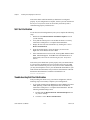
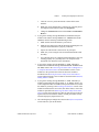
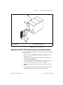
1
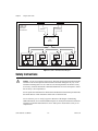
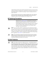
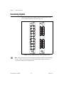
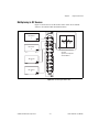
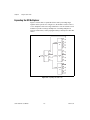
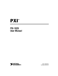
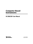
SCXI
™
SCXI-1190/1191
User Manual
SCXI-1190/1191 User Manual
February 2000 Edition
Part Number 322610A-01
Worldwide Technical Support and Product Information
www.ni.com
National Instruments Corporate Headquarters
11500 North Mopac Expressway
Austin, Texas 78759-3504
USA Tel: 512 794 0100
Worldwide Offices
Australia 03 9879 5166, Austria 0662 45 79 90 0, Belgium 02 757 00 20, Brazil 011 284 5011,
Canada (Calgary) 403 274 9391, Canada (Ontario) 905 785 0085, Canada (Québec) 514 694 8521,
China 0755 3904939, Denmark 45 76 26 00, Finland 09 725 725 11, France 01 48 14 24 24,
Germany 089 741 31 30, Greece 30 1 42 96 427, Hong Kong 2645 3186, India 91805275406,
Israel 03 6120092, Italy 02 413091, Japan 03 5472 2970, Korea 02 596 7456, Mexico (D.F.) 5 280 7625,
Mexico (Monterrey) 8 357 7695, Netherlands 0348 433466, New Zealand 09 914 0488, Norway 32 27 73 00,
Poland 0 22 528 94 06, Portugal 351 1 726 9011, Singapore 2265886, Spain 91 640 0085,
Sweden 08 587 895 00, Switzerland 056 200 51 51, Taiwan 02 2528 7227, United Kingdom 01635 523545
For further support information, see the Technical Support Resources appendix. To comment on the
documentation, send e-mail to [email protected]
© Copyright 2000 National Instruments Corporation. All rights reserved.
Important Information
Warranty
The SCXI-1190 and SCXI-1191 are warranted against defects in materials and workmanship for a period of one year from the date
of shipment, as evidenced by receipts or other documentation. National Instruments will, at its option, repair or replace equipment
that proves to be defective during the warranty period. This warranty includes parts and labor.
The media on which you receive National Instruments software are warranted not to fail to execute programming instructions,
due to defects in materials and workmanship, for a period of 90 days from date of shipment, as evidenced by receipts or other
documentation. National Instruments will, at its option, repair or replace software media that do not execute programming
instructions if National Instruments receives notice of such defects during the warranty period. National Instruments does not
warrant that the operation of the software shall be uninterrupted or error free.
A Return Material Authorization (RMA) number must be obtained from the factory and clearly marked on the outside of
the package before any equipment will be accepted for warranty work. National Instruments will pay the shipping costs of
returning to the owner parts which are covered by warranty.
National Instruments believes that the information in this document is accurate. The document has been carefully reviewed
for technical accuracy. In the event that technical or typographical errors exist, National Instruments reserves the right to
make changes to subsequent editions of this document without prior notice to holders of this edition. The reader should consult
National Instruments if errors are suspected. In no event shall National Instruments be liable for any damages arising out of
or related to this document or the information contained in it.
EXCEPT AS SPECIFIED HEREIN, NATIONAL INSTRUMENTS MAKES NO WARRANTIES, EXPRESS OR IMPLIED, AND SPECIFICALLY DISCLAIMS ANY
WARRANTY OF MERCHANTABILITY OR FITNESS FOR A PARTICULAR PURPOSE. CUSTOMER’S RIGHT TO RECOVER DAMAGES CAUSED BY FAULT OR
NEGLIGENCE ON THE PART OF NATIONAL INSTRUMENTS SHALL BE LIMITED TO THE AMOUNT THERETOFORE PAID BY THE CUSTOMER. NATIONAL
INSTRUMENTS WILL NOT BE LIABLE FOR DAMAGES RESULTING FROM LOSS OF DATA, PROFITS, USE OF PRODUCTS, OR INCIDENTAL OR
CONSEQUENTIAL DAMAGES, EVEN IF ADVISED OF THE POSSIBILITY THEREOF. This limitation of the liability of National Instruments will
apply regardless of the form of action, whether in contract or tort, including negligence. Any action against National Instruments
must be brought within one year after the cause of action accrues. National Instruments shall not be liable for any delay in
performance due to causes beyond its reasonable control. The warranty provided herein does not cover damages, defects,
malfunctions, or service failures caused by owner’s failure to follow the National Instruments installation, operation, or
maintenance instructions; owner’s modification of the product; owner’s abuse, misuse, or negligent acts; and power failure or
surges, fire, flood, accident, actions of third parties, or other events outside reasonable control.
Copyright
Under the copyright laws, this publication may not be reproduced or transmitted in any form, electronic or mechanical, including
photocopying, recording, storing in an information retrieval system, or translating, in whole or in part, without the prior written
consent of National Instruments Corporation.
Trademarks
CVI™, LabVIEW™, National Instruments™, ni.com™, NI-DAQ™, NI-SWITCH™, PXI™, and SCXI™ are trademarks of
National Instruments Corporation.
Product and company names mentioned herein are trademarks or trade names of their respective companies.
WARNING REGARDING USE OF NATIONAL INSTRUMENTS PRODUCTS
(1) NATIONAL INSTRUMENTS PRODUCTS ARE NOT DESIGNED WITH COMPONENTS AND TESTING FOR A LEVEL
OF RELIABILITY SUITABLE FOR USE IN OR IN CONNECTION WITH SURGICAL IMPLANTS OR AS CRITICAL
COMPONENTS IN ANY LIFE SUPPORT SYSTEMS WHOSE FAILURE TO PERFORM CAN REASONABLY BE
EXPECTED TO CAUSE SIGNIFICANT INJURY TO A HUMAN.
(2) IN ANY APPLICATION, INCLUDING THE ABOVE, RELIABILITY OF OPERATION OF THE SOFTWARE PRODUCTS
CAN BE IMPAIRED BY ADVERSE FACTORS, INCLUDING BUT NOT LIMITED TO FLUCTUATIONS IN ELECTRICAL
POWER SUPPLY, COMPUTER HARDWARE MALFUNCTIONS, COMPUTER OPERATING SYSTEM SOFTWARE
FITNESS, FITNESS OF COMPILERS AND DEVELOPMENT SOFTWARE USED TO DEVELOP AN APPLICATION,
INSTALLATION ERRORS, SOFTWARE AND HARDWARE COMPATIBILITY PROBLEMS, MALFUNCTIONS OR
FAILURES OF ELECTRONIC MONITORING OR CONTROL DEVICES, TRANSIENT FAILURES OF ELECTRONIC
SYSTEMS (HARDWARE AND/OR SOFTWARE), UNANTICIPATED USES OR MISUSES, OR ERRORS ON THE PART OF
THE USER OR APPLICATIONS DESIGNER (ADVERSE FACTORS SUCH AS THESE ARE HEREAFTER
COLLECTIVELY TERMED “SYSTEM FAILURES”). ANY APPLICATION WHERE A SYSTEM FAILURE WOULD
CREATE A RISK OF HARM TO PROPERTY OR PERSONS (INCLUDING THE RISK OF BODILY INJURY AND DEATH)
SHOULD NOT BE RELIANT SOLELY UPON ONE FORM OF ELECTRONIC SYSTEM DUE TO THE RISK OF SYSTEM
FAILURE. TO AVOID DAMAGE, INJURY, OR DEATH, THE USER OR APPLICATION DESIGNER MUST TAKE
REASONABLY PRUDENT STEPS TO PROTECT AGAINST SYSTEM FAILURES, INCLUDING BUT NOT LIMITED TO
BACK-UP OR SHUT DOWN MECHANISMS. BECAUSE EACH END-USER SYSTEM IS CUSTOMIZED AND DIFFERS
FROM NATIONAL INSTRUMENTS' TESTING PLATFORMS AND BECAUSE A USER OR APPLICATION DESIGNER
MAY USE NATIONAL INSTRUMENTS PRODUCTS IN COMBINATION WITH OTHER PRODUCTS IN A MANNER NOT
EVALUATED OR CONTEMPLATED BY NATIONAL INSTRUMENTS, THE USER OR APPLICATION DESIGNER IS
ULTIMATELY RESPONSIBLE FOR VERIFYING AND VALIDATING THE SUITABILITY OF NATIONAL
INSTRUMENTS PRODUCTS WHENEVER NATIONAL INSTRUMENTS PRODUCTS ARE INCORPORATED IN A
SYSTEM OR APPLICATION, INCLUDING, WITHOUT LIMITATION, THE APPROPRIATE DESIGN, PROCESS AND
SAFETY LEVEL OF SUCH SYSTEM OR APPLICATION.
Compliance
FCC/Canada Radio Frequency Interference Compliance*
Determining FCC Class
The Federal Communications Commission (FCC) has rules to protect wireless communications from interference.
The FCC places digital electronics into two classes. These classes are known as Class A (for use in industrialcommercial locations only) or Class B (for use in residential or commercial locations). Depending on where it is
operated, this product could be subject to restrictions in the FCC rules. (In Canada, the Department of
Communications (DOC), of Industry Canada, regulates wireless interference in much the same way.)
Digital electronics emit weak signals during normal operation that can affect radio, television, or other wireless
products. By examining the product you purchased, you can determine the FCC Class and therefore which of the two
FCC/DOC Warnings apply in the following sections. (Some products may not be labeled at all for FCC; if so, the
reader should then assume these are Class A devices.)
FCC Class A products only display a simple warning statement of one paragraph in length regarding interference and
undesired operation. Most of our products are FCC Class A. The FCC rules have restrictions regarding the locations
where FCC Class A products can be operated.
FCC Class B products display either a FCC ID code, starting with the letters EXN,
or the FCC Class B compliance mark that appears as shown here on the right.
Consult the FCC web site http://www.fcc.gov for more information.
FCC/DOC Warnings
This equipment generates and uses radio frequency energy and, if not installed and used in strict accordance with the
instructions in this manual and the CE Mark Declaration of Conformity**, may cause interference to radio and
television reception. Classification requirements are the same for the Federal Communications Commission (FCC)
and the Canadian Department of Communications (DOC).
Changes or modifications not expressly approved by National Instruments could void the user’s authority to operate
the equipment under the FCC Rules.
Class A
Federal Communications Commission
This equipment has been tested and found to comply with the limits for a Class A digital device, pursuant to part 15
of the FCC Rules. These limits are designed to provide reasonable protection against harmful interference when the
equipment is operated in a commercial environment. This equipment generates, uses, and can radiate radio frequency
energy and, if not installed and used in accordance with the instruction manual, may cause harmful interference to
radio communications. Operation of this equipment in a residential area is likely to cause harmful interference in
which case the user will be required to correct the interference at his own expense.
Canadian Department of Communications
This Class A digital apparatus meets all requirements of the Canadian Interference-Causing Equipment Regulations.
Cet appareil numérique de la classe A respecte toutes les exigences du Règlement sur le matériel brouilleur du
Canada.
Class B
Federal Communications Commission
This equipment has been tested and found to comply with the limits for a Class B digital device, pursuant to part 15
of the FCC Rules. These limits are designed to provide reasonable protection against harmful interference in a
residential installation. This equipment generates, uses and can radiate radio frequency energy and, if not installed
and used in accordance with the instructions, may cause harmful interference to radio communications. However,
there is no guarantee that interference will not occur in a particular installation. If this equipment does cause harmful
interference to radio or television reception, which can be determined by turning the equipment off and on, the user
is encouraged to try to correct the interference by one or more of the following measures:
• Reorient or relocate the receiving antenna.
• Increase the separation between the equipment and receiver.
•
•
Connect the equipment into an outlet on a circuit different from that to which the receiver is connected.
Consult the dealer or an experienced radio/TV technician for help.
Canadian Department of Communications
This Class B digital apparatus meets all requirements of the Canadian Interference-Causing Equipment Regulations.
Cet appareil numérique de la classe B respecte toutes les exigences du Règlement sur le matériel brouilleur du
Canada.
European Union - Compliance to EEC Directives
Readers in the EU/EEC/EEA must refer to the Manufacturer's Declaration of Conformity (DoC) for information**
pertaining to the CE Mark compliance scheme. The Manufacturer includes a DoC for most every hardware product
except for those bought for OEMs, if also available from an original manufacturer that also markets in the EU, or
where compliance is not required as for electrically benign apparatus or cables.
* Certain exemptions may apply in the USA, see FCC Rules §15.103 Exempted devices, and §15.105(c).
Also available in sections of CFR 47.
** The CE Mark Declaration of Conformity will contain important supplementary information and instructions
for the user or installer.
Conventions
The following conventions are used in this manual:
This icon denotes a note, which alerts you to important information.
This icon denotes a caution, which advises you of precautions to take to
avoid injury, data loss, or a system crash.
This icon denotes a warning, which advises you of precautions to take to
avoid being electrically shocked.
bold
Bold text denotes items that you must select or click on in the software,
such as menu items and dialog box options. Bold text also denotes
parameter names.
italic
Italic text denotes variables, emphasis, a cross reference, or an introduction
to a key concept. This font also denotes text that is a placeholder for a word
or value that you must supply.
monospace
Text in this font denotes text or characters that you should enter from the
keyboard, sections of code, programming examples, and syntax examples.
This font is also used for the proper names of disk drives, paths, directories,
programs, subprograms, subroutines, device names, functions, operations,
variables, filenames and extensions, and code excerpts.
monospace bold
Bold text in this font denotes the messages and responses that the computer
automatically prints to the screen. This font also emphasizes lines of code
that are different from the other examples.
SCXI-119X
Refers to the both the SCXI-1190 module and the SCXI-1191 module.
Contents
Chapter 1
Installing and Configuring the SCXI-119X
About the SCXI-119X....................................................................................................1-1
Installing the Software ...................................................................................................1-1
Installing the Hardware..................................................................................................1-2
Unpacking........................................................................................................1-2
Installing the SCXI-119X Module into an SCXI Chassis ...............................1-3
Connecting the SCXI-119X to a DAQ Device or Computer-Based
Instrument.....................................................................................................1-4
Connecting the SCXI-119X to a DAQ Device in a PXI Combination
Chassis ..........................................................................................................1-6
Configuration and Self-Test...........................................................................................1-7
Auto-Detecting Modules .................................................................................1-8
Manually Adding Modules..............................................................................1-9
Self-Test Verification ......................................................................................1-10
Troubleshooting Self-Test Verification...........................................................1-10
Removing the SCXI-119X .............................................................................................1-12
Removing the SCXI-119X from an SCXI Chassis..........................................1-12
Removing the SCXI-119X from Measurement & Automation Explorer........1-13
Chapter 2
Using the SCXI-119X
Functional Overview......................................................................................................2-1
Safety Instructions .........................................................................................................2-2
RF Switching Precautions..............................................................................................2-3
Contact Protection..........................................................................................................2-3
Connecting Signals ........................................................................................................2-4
Multiplexing to RF Sources.............................................................................2-5
Expanding the RF Multiplexer ........................................................................2-6
Appendix A
Specifications
Appendix B
Common Questions
© National Instruments Corporation
vii
SCXI-1190/1191 User Manual
Contents
Appendix C
Technical Support Resources
Glossary
Index
Figures
Figure 1-1.
Figure 1-2.
Figure 1-3.
Installing the SCXI-119X into an SCXI Chassis .................................. 1-3
Connecting an SCXI Chassis to a DAQ Device or
Computer-Based Instrument ................................................................. 1-6
Removing the SCXI-119X .................................................................... 1-13
Figure 2-1.
Figure 2-2.
Figure 2-3.
Figure 2-4.
SCXI-119X Module Block Diagram..................................................... 2-2
SCXI-1190 SMB Connectors, SCXI-1191 SMA Connectors .............. 2-4
Connecting the SCXI-119X .................................................................. 2-5
Expanding the SCXI-119X ................................................................... 2-6
SCXI-1190/1191 User Manual
viii
www.ni.com
Installing and Configuring the
SCXI-119X
1
This manual describes the electrical and mechanical characteristics of the
SCXI-1190 (quad 1 × 4, 50 Ω, 1.3 GHz bandwidth) and the SCXI-1191
(quad 1 × 4, 50 Ω, 4 GHz bandwidth) multiplexer modules for the SCXI
bus and contains information concerning their installation and operation.
About the SCXI-119X
This section summarizes the features and operation of the SCXI-119X
switch modules. In addition, refer to Appendix A, Specifications,
for detailed specifications of the switch module.
The SCXI-119X modules are general-purpose, quad 4-channel,
high-bandwidth multiplexing switches. The SCXI-119X uses single-pole
double-throw, high-bandwidth relays capable of switching signals from
DC to 1.3 GHz bandwidth (SCXI-1190) and from DC to 4 GHz bandwidth
(SCXI-1191). The characteristic impedance of the channels is 50 Ω. For the
SCXI-1190, the maximum rated voltage of the switch is 24 VDC, and the
maximum rated current is 1 A at 24 V. For the SCXI-1191, the maximum
rated voltage of the switch is 30 VDC, and the maximum rated current is
30 Vrms at 0.33 ADC.
Installing the Software
You can control the SCXI-119X programmatically in an application
development environment (ADE) using NI-SWITCH. The supported
ADEs include LabVIEW, LabWindows/CVI, Visual Basic, and C or C++
environments. The following steps describe how to install your SCXI-119X
software.
1.
© National Instruments Corporation
Install your ADE if you have not already done so. Refer to your ADEs
documentation for the software installation instructions.
1-1
SCXI-1190/1191 User Manual
Chapter 1
Installing and Configuring the SCXI-119X
2.
Install the NI-SWITCH software that came on a CD with your
SCXI-119X. The CD includes the software required to configure and
to program your SCXI-119X module.
a.
Insert your National Instruments NI-SWITCH software CD into
the CD-ROM drive.
b.
Click Install in the installation window that will appear
automatically.
Note If the installation window does not appear, double-click the My Computer icon on
your PC desktop. Find the CD drive, and double-click it. In the CD directory, double-click
install.exe.
Installing the Hardware
The following section describes how to unpack, install, and connect your
SCXI-119X for use with an SCXI chassis.
Make sure you read and understand all the safety information in this manual
before you install an SCXI module.
Caution
Unpacking
Your SCXI-119X module is shipped in an antistatic package to prevent
electrostatic discharge damage to the module. Electrostatic discharge can
damage several components on the module. To avoid damaging the
module, take the following precautions:
SCXI-1190/1191 User Manual
•
Ground yourself through a grounding strap or by holding a grounded
object.
•
Touch the antistatic package to a metal part of your SCXI chassis
before removing the module from the package.
•
Remove the module from the package, and inspect the module for
loose components or any other sign of damage. Notify National
Instruments if the module appears damaged in any way. Do not install
a damaged module into your SCXI chassis.
•
Never touch the exposed pins of connectors to avoid possible
electrostatic discharge.
1-2
www.ni.com
Chapter 1
Installing and Configuring the SCXI-119X
Installing the SCXI-119X Module into an SCXI Chassis
You need the following items to complete the installation:
•
SCXI-119X module
•
SCXI chassis
Follow these steps to install your SCXI-119X module into an SCXI chassis
while referring to Figure 1-1.
5
6
®
7
SC
MA
IN
XI
FR
AM
E
8
1
2
3
1
2
3
Slot 1
Slot 2
Slot 3
4
5
6
4
Slot 4
SCXI Chassis
SCXI Chassis Power Switch
7
8
SCXI-119X (SCXI-1191 Shown)
SCXI Module Thumbscrews
Figure 1-1. Installing the SCXI-119X into an SCXI Chassis
1.
Turn off the computer that contains the DAQ device or computer-based
instrument, or disconnect the computer from your SCXI chassis.
2.
Turn off the SCXI chassis.
Do not insert the SCXI-119X module into a chassis that is turned on as doing so
could damage the module.
Caution
3.
© National Instruments Corporation
Remove the protective plastic caps from the module’s thumbscrews so
that the module will insert correctly.
1-3
SCXI-1190/1191 User Manual
Chapter 1
Installing and Configuring the SCXI-119X
4.
Insert the SCXI-119X module into slot 1. Gently guide the module into
the module guides and push it to the back of the slot until the
connectors make good contact. The module must be firmly engaged;
however, do not force the module into place. If the module is not
sliding easily into the chassis, check for correct insertion into the
module guides.
Note When installing the SCXI-119X module in an SCXI chassis, slot 1 should be filled
first, then fill slot 2 with the next SCXI-119X.
5.
Insert any other SCXI modules into the remaining slots in the same
manner as described in step 4.
6.
Secure all the SCXI-119X modules to the SCXI chassis by tightening
both module thumbscrews.
Connecting the SCXI-119X to a DAQ Device or Computer-Based
Instrument
You need the following items:
•
SCXI chassis with the SCXI modules installed (Refer to the Installing
the SCXI-119X Module into an SCXI Chassis section.)
•
SCXI cable assembly, which consists of a cable adapter and a cable
•
An installed National Instruments DAQ device or computer-based
instrument that is able to control the SCXI chassis such as the NI 4060
•
1/4 in. flathead screwdriver
Consult your SCXI chassis documentation, other SCXI module
documentation, and DAQ device or computer-based instrument
documentation for additional instructions and warnings. Your SCXI-119X
module and any other SCXI modules should already be installed in the
chassis according to their installation instructions.
You must select one of the modules in the chassis to be the cabled
module—the module to which the SCXI cable assembly will be connected.
If the chassis contains at least one SCXI-1140 module, select an
SCXI-1140 as the cabled module; otherwise, select one of the remaining
modules.
SCXI-1190/1191 User Manual
1-4
www.ni.com
Chapter 1
Installing and Configuring the SCXI-119X
To connect the chassis to a DAQ device for multiplexed operation,
complete the following steps while referring to Figure 1-2:
1.
Turn off both the SCXI chassis and the computer that contains the
DAQ device or computer-based instrument.
2.
Insert the cable adapter into the back of the SCXI chassis aligned with
the module that is to be connected to the DAQ device or
computer-based instrument. See your cable assembly’s installation
guide for more specific information.
3.
Connect the cable to the back of the cable adapter, ensuring that the
cable fits securely.
4.
Connect the other end of the cable to the DAQ device or
computer-based instrument that you will use to control the SCXI
system.
5.
Check the cable installation, making sure the connectors are securely
fastened at both ends.
6.
Turn on the SCXI chassis.
7.
Turn on the computer.
8.
If you have already installed the appropriate software, you are ready to
configure the SCXI-119X. If you have not installed the appropriate
software, refer to the Installing the Software section.
© National Instruments Corporation
1-5
SCXI-1190/1191 User Manual
Chapter 1
Installing and Configuring the SCXI-119X
1
4
3
®
2
1
2
SCXI Chassis Power Switch
Cable Adapter
3
4
Cable
DAQ Device or Computer-Based Instrument
Figure 1-2. Connecting an SCXI Chassis to a DAQ Device or
Computer-Based Instrument
Connecting the SCXI-119X to a DAQ Device in a PXI Combination
Chassis
To connect the SCXI-119X to a DAQ device in a PXI combination chassis,
such as the PXI-1010 or PXI-1011, you need the following items:
•
PXI combination chassis with the SCXI modules installed
•
National Instruments PXI MIO DAQ device, or a computer-based
instrument that is capable of controlling SCXI, installed in the right
most slot of the PXI section of the combination chassis
A PXI combination chassis can use both SCXI and PXI modules at the
same time. Because the connection between the SCXI backplane and the
PXI backplane is made through a local bus interface to a PXI multifunction
I/O module installed in the right most slot, no external cabling is needed to
connect one PXI multifunction I/O module to the SCXI bus.
SCXI-1190/1191 User Manual
1-6
www.ni.com
Chapter 1
Installing and Configuring the SCXI-119X
You should have already installed your SCXI-119X module and any other
SCXI modules in the chassis according to their installation instructions.
To use the SCXI-119X module with a DAQ device or computer-based
instrument in a PXI combination chassis, turn on the SCXI chassis.
Consult your PXI chassis documentation, other SCXI module
documentation, and DAQ device or computer-based instrument
documentation for additional instructions and warnings.
If you have already installed the appropriate software, you are ready to
configure the SCXI-119X. If you have not installed the appropriate
software, refer to the Installing the Software section.
Configuration and Self-Test
NI-SWITCH installed the Measurement & Automation Explorer icon
on your PC desktop. This utility allows you to configure and test your
National Instruments hardware.
Follow these steps to configure your SCXI system:
1.
Double-click the Measurement & Automation Explorer icon on
your PC desktop. Click the + next to Devices and Interfaces.
If you are adding new modules to an existing chassis, go to step 4.
If you are inserting modules into an empty chassis, go to step 2.
2.
Add a new chassis to the configured devices and interfaces by
right-clicking on Devices and Interfaces and selecting Insert. Select
the appropriate chassis from the list box and click OK.
3.
Configure the chassis.
© National Instruments Corporation
a.
Select a Chassis ID. The ID is an integer value you choose to
uniquely identify the chassis for programming and scanning.
b.
Select the Chassis Address. This selection is needed to address
the chassis in a multichassis SCXI system. Unless you are using
multiple chassis with the same DAQ device or computer-based
instrument, select a chassis address of zero, which is the
factory-default setting of all SCXI chassis. If you are using
multiple chassis, refer to your SCXI chassis user manual for
further information.
c.
For remote SCXI chassis, such as the SCXI 2000 or a SCXI
chassis using SCXI 2400 modules, you also need to select the
Baud Rate and COM Port.
d.
After completing the chassis configuration, click Next.
1-7
SCXI-1190/1191 User Manual
Chapter 1
Installing and Configuring the SCXI-119X
You now have the choice of automatically detecting which modules are
installed in the chassis or manually adding them.
•
If you have just added the chassis to Devices and Interfaces, you can
automatically detect new modules.
•
If the chassis was already listed in Devices and Interfaces, you must
manually add new modules.
Go to the appropriate section that follows to continue the software
configuration of your chassis.
If you need further help during the configuration process, open
Measurement & Automation Help by selecting Help»Help Topics in your
Measurement & Automation Explorer window.
Auto-Detecting Modules
If you selected auto-detect, you must have your chassis connected to your
DAQ device or computer-based instrument, except in the case of a remote
chassis, which you should connect to the computer using a serial port cable.
Before auto-detecting modules, refer to the Connecting the SCXI-119X to
a DAQ Device or Computer-Based Instrument section.
To auto-detect your SCXI module(s), follow these steps:
1.
Make sure the chassis power is turned on.
2.
In the auto-detect window, select Yes under Auto-Detect Modules?
and click Next. If your chassis is a remote SCXI chassis, go to step 5,
otherwise go to step 3.
3.
Select your communication path, which is the device in your PC or
PXI system directly connected to the chassis, and click Next.
4.
When the modules are detected, select the module that is connected to
your communication device by the cable.
5.
Click Finish.
Measurement & Automation Explorer should now recognize your SCXI
chassis and SCXI module(s). If the software did not recognize your
modules, check your cable connections and retry auto-detecting.
Alternatively, try installing the modules manually before taking the
troubleshooting measures discussed in the Troubleshooting Self-Test
Verification section.
SCXI-1190/1191 User Manual
1-8
www.ni.com
Chapter 1
Installing and Configuring the SCXI-119X
Note If the Measurement & Automation Explorer recognized any module as an SCXI
custom module, you may be using an old version of NI-DAQ, the data acquisition driver
software. You can download the latest version of NI-DAQ for free at www.ni.com.
Manually Adding Modules
If you did not auto-detect your SCXI modules, you must add each of your
modules separately. Use the following steps to manually add modules:
1.
In the auto-detect window, select No under Auto-Detect Modules?
and click Finish.
2.
Display the list of devices and interfaces by clicking the + next to
Devices and Interfaces.
3.
The chassis you added is now displayed in the list. Display the list of
modules in the chassis by clicking the + next to the Chassis name.
4.
Right-click on the appropriate physical installation slot and select
Insert.
Note When looking at the front of the SCXI chassis, slot 1 is the left most slot.
5.
Select the module installed in that slot and click Next.
Note If the appropriate module name does not appear on the list, you may be using an old
version of NI-DAQ, the data acquisition driver software. You can download the latest
version of NI-DAQ for free at www.ni.com.
6.
7.
Configure your module as follows:
•
If the selected module is physically connected to a National
Instruments DAQ device or computer-based instrument, select
that device by using the Connected to control. If you want this
device to control the chassis, confirm that the checkbox labeled
This device will control the chassis is checked.
•
If the selected module is not connected to a National Instruments
DAQ device or computer-based instrument, select none.
•
In the Operating Mode box, select Multiplexed Mode.
Click Finish.
If you need to manually install more SCXI-119X modules in your chassis,
repeat steps 3 through 6 to configure each module.
© National Instruments Corporation
1-9
SCXI-1190/1191 User Manual
Chapter 1
Installing and Configuring the SCXI-119X
Your SCXI chassis and SCXI module(s) should now be configured
properly. If your configuration is complete, test the system as described in
the Self-Test Verification section to ensure that your SCXI system is
communicating properly with the device.
Self-Test Verification
To test the successful configuration of your system, complete the following
steps:
1.
Double-click the Measurement & Automation Explorer icon on
your PC desktop:
2.
Verify that the chassis power is on and that the chassis is correctly
connected to a DAQ device or computer-based instrument.
3.
Display the list of devices and interfaces by clicking the + next to
Devices and Interfaces.
4.
From the list that appears, locate the chassis you want to test.
Right-click on the chassis and select Test.
5.
If the communication test is successful, a message The chassis has
been verified appears. Click OK. If the communication test is
unsuccessful, refer to the Troubleshooting Self-Test Verification
section.
Your SCXI system should now operate properly with your ADE software.
If you experience problems between your SCXI system and your ADE,
refer to the Troubleshooting Self-Test Verification section. Additionally,
you may find it helpful to refer to your NI-SWITCH documentation, your
ADE software documentation, and your chassis documentation. National
Instruments documentation is available to download free at
www.ni.com/manuals.
Troubleshooting Self-Test Verification
If the preceding test did not verify your chassis configuration, take the
following steps to successfully complete system configuration:
1.
If you get the warning message Unable to test chassis at this
time, probably you have not designated at least one module as
connected to a DAQ device or computer-based instrument. Take the
following troubleshooting actions:
SCXI-1190/1191 User Manual
a.
Double-click the Measurement & Automation Explorer icon
on your PC desktop.
b.
Click the + next to Devices and Interfaces.
1-10
www.ni.com
Chapter 1
2.
Installing and Configuring the SCXI-119X
c.
Click the + next to your SCXI chassis to show all the SCXI
modules.
d.
Right-click on the module that is connected to your DAQ device
or computer-based instrument and select Properties.
e.
Change the Connected to selection from None to Connected to:
Device x.
If you get the warning message Failed to find followed by the
module codes and the message Unable to communicate with
chassis, take the following troubleshooting actions:
a.
Make sure that the SCXI chassis is powered on.
b.
Make sure the cable between the SCXI chassis and DAQ device or
computer-based instrument is properly connected.
c.
Inspect the cable and the connectors for any bent pins.
d.
Make sure you are using the correct National Instruments cable
assembly.
e.
Test your DAQ device or computer-based instrument to verify it is
working properly. See your DAQ device or computer-based
instrument user manual for more information.
3.
If you get the warning message Failed to find, followed by
module codes and then the message Instead found: module with
ID 0Xxx, return to the Connecting the SCXI-119X to a DAQ Device
or Computer-Based Instrument section and make sure the correct
module is in the specified slot. Delete the incorrect module as
described in the Removing the SCXI-119X from an SCXI Chassis
section and then add the correct module as described in the Manually
Adding Modules section.
4.
If you get the warning message Failed to find, followed by a
module code and then the message Slot x is empty, check to see
if the configured module is installed in the specified slot. If not, install
the module by referring to the Installing the Hardware section. If the
module is installed in the correct slot, turn off the chassis, remove the
module as specified in the Removing the SCXI-119X from an SCXI
Chassis section, and verify that no connector pins are bent on the rear
signal connector. Reinstall the module, ensuring the module is fully
inserted and properly aligned in the slot.
5.
After checking the preceding items, return to the Self-Test Verification
section and retest your SCXI chassis.
© National Instruments Corporation
1-11
SCXI-1190/1191 User Manual
Chapter 1
Installing and Configuring the SCXI-119X
Removing the SCXI-119X
This section describes how to remove the SCXI-119X from an SCXI
chassis.
Removing the SCXI-119X from an SCXI Chassis
Make sure you read and understand all the safety information in this
manual before you remove an SCXI module. You need the following items
to complete this task:
•
SCXI chassis with the SCXI-119X module(s) installed
•
1/4 in. flathead screwdriver
Consult the documentation for your SCXI or PXI (if you are using a
combination chassis) chassis and accessories for additional instructions
and warnings. To remove the SCXI-119X module from an SCXI chassis,
follow these steps while referring to Figure 1-3:
1.
Remove all signals connected to the SCXI-119X.
2.
Turn off the SCXI chassis power.
Do not remove the SCXI-119X module from a chassis that is turned on as doing
so could damage the module.
Caution
SCXI-1190/1191 User Manual
3.
Rotate the thumbscrews securing the SCXI-119X to the chassis
counter-clockwise until they are loose, but do not completely remove
the thumbscrews.
4.
Remove the SCXI-119X by pulling steadily on both thumbscrews until
the module slides completely out.
1-12
www.ni.com
Chapter 1
Installing and Configuring the SCXI-119X
2
1
®
SC
MA
IN
XI
FR
AM
E
3
4
1
2
SCXI Chassis Power Switch
SCXI Chassis
3
4
SCXI-119X (SCXI-1191 Shown)
SCXI Module Thumbscrews
Figure 1-3. Removing the SCXI-119X
Removing the SCXI-119X from Measurement & Automation Explorer
To remove a module from Measurement & Automation Explorer, complete
the following steps:
1.
Double-click the Measurement & Automation Explorer icon on
your PC desktop.
2.
Display the list of installed devices and interfaces by clicking the +
next to Devices and Interfaces.
3.
Locate the chassis in the list of installed devices. Display the list of
modules in the chassis by clicking the + next to Chassis.
4.
Right-click on the module or chassis you want to delete and select
Delete.
5.
You will be presented a confirmation window. Click Yes to continue
deleting the module or chassis or No to cancel this action.
© National Instruments Corporation
1-13
SCXI-1190/1191 User Manual
Chapter 1
Installing and Configuring the SCXI-119X
Note Deleting an SCXI chassis deletes all modules in the chassis. All configuration
information for these modules is also lost.
Your SCXI chassis and/or SCXI module(s) should now be removed from
the list of installed devices in Measurement & Automation Explorer.
SCXI-1190/1191 User Manual
1-14
www.ni.com
Using the SCXI-119X
2
This chapter contains a functional overview, safety instructions, and
connection possibilities of the SCXI-119X multiplexer module.
Functional Overview
The SCXI-119X modules are general-purpose, quad 4-channel,
high-bandwidth multiplexing switches. The SCXI-1190 uses single-pole
double-throw, high-bandwidth relays capable of switching signals from
DC to 1.3 GHz. Functionally identical, the SCXI-1191 has a bandwidth of
DC to 4 GHz. Figure 2-1 illustrates the key functional components of the
SCXI-119X multiplexer module.
© National Instruments Corporation
2-1
SCXI-1190/1191 User Manual
Chapter 2
Using the SCXI-119X
SCXI-1190
SCXI-1191
Hardware
Architecture
Rear Signal
Connector
SCXIbus
Relay Controller
and
Drivers
Relay Control Bus
comA 3A
2A
1A
0A
comB 3B
2B
1B
0B
comC 3C
2C
1C
0C
comD 3D
2D
1D
0D
Figure 2-1. SCXI-119X Module Block Diagram
Safety Instructions
Cautions Do not operate damaged equipment. The safety protection features built into this
instrument can become impaired if the instrument becomes damaged in any way. If the
instrument is damaged, do not use it until service-trained personnel can check its safety.
If necessary, return the instrument to National Instruments for service and repair to ensure
that its safety is not compromised.
Do not operate this instrument in a manner that contradicts the information specified in this
document. Misuse of this instrument could result in a shock hazard.
Do not substitute parts or modify equipment. Because of the danger of introducing
additional hazards, do not install unauthorized parts or modify the instrument. Return the
instrument to National Instruments for service and repair to ensure that its safety is not
compromised.
SCXI-1190/1191 User Manual
2-2
www.ni.com
Chapter 2
Using the SCXI-119X
Connections that exceed any of the maximum signal ratings on the SCXI-119X can create
a shock or fire hazard or can damage any or all of the devices connected to the SCXI-119X.
National Instruments is not liable for any damages or injuries resulting from incorrect
signal connections.
Clean the instrument and accessories by brushing off light dust with a soft, nonmetallic
brush. Remove other contaminants with a stiff nonmetallic brush. The unit must be
completely dry and free from contaminants before returning to service.
RF Switching Precautions
The SCXI-119X is a reflective switch, meaning that any channels not
switched to the common channel are unterminated, and any signal on an
unterminated channel is reflected to its source. For most low-power
switching applications this reflection is not a problem. However, operation
with an unterminated output can damage some high-power RF sources.
Consult your RF source documentation for more information about
connecting to unterminated channels.
Warning Do not exceed the channel-to-ground rating of 24 V on the SCXI-1190 and
30 Vrms or DC for the SCXI-1191. Any connections that exceed the maximum voltage for
the SCXI-119X can result in an electrical shock hazard and damage to the switch module
and any or all of the modules connected to the SCXI backplane. National Instruments is
not liable for any damages or injuries resulting from exceeding maximum voltage ratings.
Refer to Appendix A, Specifications, for specific information.
Always disconnect all signals from the front connectors and power down the
SCXI chassis before removing the SCXI-119X from the chassis. Observe electrostatic
discharge handling precautions during and after removal of the module, or when
connecting and disconnecting signals on the front panel.
Caution
Contact Protection
The contacts of the relay are rated for a life of 5 × 10⁶ mechanical operations
when operated with no signal or a very small signal present. At full rated power of 1 A at
24 VDC for the SCXI-1190 or of 30 VDC at 1/3 ADC for the SCXI-1191, the life of the
switch is downgraded to 100,000 operations. If your setup allows, it is always best to turn
off the input signals connected to the switch module during the switching operation to
avoid contact arcing within the switch. Switching large inductive loads can also cause
contact arcing. In such instances, install a flyback diode or varistor across the inductance
to protect the switch.
Caution
© National Instruments Corporation
2-3
SCXI-1190/1191 User Manual
Chapter 2
Using the SCXI-119X
Connecting Signals
The SCXI-1190 has push-on SMB connectors, and the SCXI-1191 has
screw-on SMA connectors as shown in Figure 2-2.
N ATION AL
IN STRUMEN TS
N ATION AL
IN STRUMEN TS
Figure 2-2. SCXI-1190 SMB Connectors, SCXI-1191 SMA Connectors
Note The power-up and reset state of the different multiplexer banks are as follows: banks
A and C, channel 0 is connected to the COM terminal; banks B and D, channel 3 is
connected is connected to the COM terminal.
SCXI-1190/1191 User Manual
2-4
www.ni.com
Chapter 2
Using the SCXI-119X
Multiplexing to RF Sources
Figure 2-3 shows how to use the SCXI-119X to select one of four RF
sources to be routed to a RF measurement device.
N ATION AL
IN STRUMEN TS
RF Source
1
RF Source
2
RF Measurement Device
• Scopes
• Spectrum Analyzers
• Power Meters
RF Source
3
RF Source
4
Figure 2-3. Connecting the SCXI-119X
© National Instruments Corporation
2-5
SCXI-1190/1191 User Manual
Chapter 2
Using the SCXI-119X
Expanding the RF Multiplexer
Figure 2-4 shows how to expand the SCXI-119X by cascading stages
together. In the specific case of Figure 2-4, the module is used to create a
13 to 1 multiplexer with a two-stage architecture. You can cascade several
modules to provide even larger multiplexers. Cascading multiplexers
increases insertion loss, creates propagation delays, and may have other RF
effects.
3D
2D
comD
MUX
D
1D
0D
3A
3C
2A
comA
MUX
A
2C
comC
1A
MUX
C
0A
1C
0C
3B
2B
comB
MUX
B
1B
0B
Figure 2-4. Expanding the SCXI-119X
SCXI-1190/1191 User Manual
2-6
www.ni.com
A
Specifications
This appendix lists the specifications for the SCXI-1190 and the
SCXI-1191 multiplexer modules. These specifications are typical at 25 °C
unless otherwise noted.
SCXI-1190
Input Characteristics
Number of relays per bank..................... 3
Number of banks.................................... 4
Common-mode voltage
Channel to earth .............................. 24 VDC
Maximum switching voltage
AC ................................................... 24 Vrms
DC ................................................... 24 VDC
Maximum switching capacity per channel
DC ................................................... 1 A at 24 V
AC ................................................... 1 Arms at 24 V
Maximum switching
power per channel .................................. 24 W
Contact on resistance (initial) ................ 100 mΩ max
Contact material ..................................... Gold-clad silver
© National Instruments Corporation
A-1
SCXI-1190/1191 User Manual
Appendix A
Specifications for SCXI-1190
RF Performance Characteristics
Characteristic impedance (Z0) ................50 Ω
Insertion loss at:
≤100 MHz........................................<0.4 dB
≤500 MHz........................................<0.9 dB
≤1.3 GHz .........................................<1.5 dB
≤2 GHz ............................................<3 dB
VSWR at:
≤100 MHz........................................<1.15
≤500 MHz........................................<1.35
≤1.3 GHz .........................................<1.5
≤2 GHz ............................................<2.5 dB
Isolation:
≤500 MHz........................................<–62 dB
≤1.3 GHz .........................................<–50 dB
≤2 GHz ............................................<–30 dB
Rise time .................................................<300 ps
Signal delay ............................................<3 ns
Maximum RF carry power
at 900 MHz ......................................10 W
Note Refer to the cautions and warning in Chapter 2, Using the SCXI-119X, for important
information about using your SCXI-1190 with high-power signals.
Dynamic Characteristics
Relay operate time (at 20 °C)
Typical.............................................15 ms
Relay release time (at 20 °C)
Typical.............................................15 ms
Expected life
Mechanical (no load).......................5 × 106 operations
Electrical at maximum
switching capacity ...........................105 operations
SCXI-1190/1191 User Manual
A-2
www.ni.com
Appendix A
Specifications for SCXI-1190
Exceeding the maximum switching capability will decrease the expected life of
the SCXI-1190.
Caution
Power Requirement
+5 VDC
Maximum (all relays closed) .......... 600 mA
Physical
Dimensions............................................. 17.30 by 19.56 by 3.02 cm
(6.81 by 7.70 by 1.19 in.)
I/O connector.......................................... 5 SMB female per bank
Environment
Operating temperature ..........................0 to 50 °C
Storage temperature..............................–20 to 70 °C
Relative humidity ................................... 5% to 85% noncondensing
Electromagnetic compatibility
(EMC) emissions ............................ Refer to the document supplied
with the chassis for compliance to
relevant directives.
EMI ................................................. FCC Class A compliant
Certifications and Compliances
CE Mark Compliance
See the Declaration of Conformity sheet accompanying product.
© National Instruments Corporation
A-3
SCXI-1190/1191 User Manual
Appendix A
Specifications for SCXI-1191
SCXI-1191
Input Characteristics
Number of relays per bank .....................3
Number of banks ....................................4
Common-mode voltage
Channel to earth...............................30 Vrms or DC
Maximum switching voltage
AC....................................................30 Vrms
DC....................................................30 VDC
Maximum switching capacity per channel
DC....................................................30 VDC at 0.33 ADC
AC....................................................30 Vrms at 0.33 Arms
Maximum switching
power per channel...................................10 W
Contact on resistance (initial) .................200 mΩ max
Contact material......................................Gold
RF Performance Characteristics
Characteristic impedance (Z0) ................50 Ω
Insertion loss at:
< 2.5 GHz ........................................< 0.6 dB
< 4 GHz ...........................................< 0.9 dB
VSWR at:
< 2.5 GHz ........................................< 1.3
< 4 GHz ...........................................< 1.5
Isolation:
< 2.5 GHz ........................................< –60 dB
< 4 GHz ...........................................< –55 dB
Maximum RF carry power
at 900 MHz ......................................10 W
SCXI-1190/1191 User Manual
A-4
www.ni.com
Appendix A
Specifications for SCXI-1191
Note Refer to the warning and cautions in Chapter 2, Using the SCXI-119X, for important
information about using your SCXI-1191 with high-power signals.
Dynamic Characteristics
Relay operate time (at 20 °C)
Typical ............................................ 15 ms
Relay release time (at 20 °C)
Typical ............................................ 15 ms
Expected life
Mechanical (no load) ...................... 5 × 10⁶ operations
Electrical at maximum
switching capacity........................... 105 operations
Exceeding the maximum switching capability will decrease the expected life of
the SCXI-1191.
Caution
Power Requirement
+5 VDC
Maximum (all relays closed) .......... 950 mW
Physical
Dimensions............................................. 17.30 by 19.56 by 3.02 cm
(6.81 by 7.70 by 1.19 in.)
I/O connector.......................................... 5 SMA female per bank
Environment
Operating temperature ..........................0 to 50 °C
Storage temperature..............................–20 to 70 °C
Relative humidity ................................... 5% to 85% noncondensing
Electromagnetic compatibility
(EMC) emissions ............................ Refer to the document supplied
with the chassis for compliance to
relevant directives.
EMI ................................................. FCC Class A compliant
© National Instruments Corporation
A-5
SCXI-1190/1191 User Manual
Appendix A
Specifications for SCXI-1191
Certifications and Compliances
CE Mark Compliance
See the Declaration of Conformity sheet accompanying product.
SCXI-1190/1191 User Manual
A-6
www.ni.com
B
Common Questions
This appendix addresses common questions you may have while using
your SCXI-119X multiplexer module.
The SCXI-1190 is listed to have a 1.3 GHz bandwidth. Can I use it at
2 GHz bandwidth?
The SCXI-1190 can definitely be used at 2 GHz, as long as the isolation,
VSWR, and attenuation levels are acceptable for your particular
application. Refer to Appendix A, Specifications, for a complete list of the
parameters at 2 GHz.
What should I do if the software detects the module but the switches do
not switch?
•
Verify that the switches do not switch by trying to close and open the
switches. You can verify the switches’ functionality by using the
NI-SWITCH front panel. Access the front panel by clicking on
Start»Programs»National Instruments Switch»NI-Switch Soft
Front Panel.
•
Also be sure to check the return codes of the NI-SWITCH operation to
ensure that there are no errors (negative value) or warnings (positive
value).
•
Finally, verify that your code is correct. For reference, see the
examples described in the NI-SWITCH Software User Manual.
The NI-SWITCH driver ships with several examples in source code.
Compare your algorithm to those in the examples.
Do I need to program the switch module myself?
The SCXI-119X comes with the NI-SWITCH driver software, which
exports the full functionality of the module. NI-SWITCH handles the
complex issues of direct memory access, interrupts, and operating system
interfacing for you. All you need to do is make high-level calls to these
functions from your ADE.
© National Instruments Corporation
B-1
SCXI-1190/1191 User Manual
Appendix B
Common Questions
One of my modules doesn’t switch properly anymore. What’s wrong?
One of the relays has probably worn out. Relays are mechanical devices
and have a limited switching lifetime. Call National Instruments for
information on replacing your relays.
What is VSWR, and how does it affect my system?
VSWR stands for Voltage Standing Wave Ratio; it is a measure of the
reflection on a transmission line. The percentage of a signal reflected back
to the source is equal to (VSWR-1)/(VSWR+1). This means that a VSWR
of 1 is optimum, with no reflected signal. On higher power applications, a
large VSWR can damage the output stage of the source. High VSWR also
means that a large percentage of the power from the source cannot be
delivered to the load.
What is isolation, and why is it important?
Isolation is a measure of the amount of cross-talk between channels. For
example, if a 1 Vp-p signal is isolated by 40 dB to another channel, then
10 mVp-p will be seen on the adjacent channel (in addition to the signal
already on the channel).
SCXI-1190/1191 User Manual
B-2
www.ni.com
Technical Support Resources
C
This appendix describes the comprehensive resources available to you in
the Technical Support section of the National Instruments Web site and
provides technical support telephone numbers for you to use if you have
trouble connecting to our Web site or if you do not have internet access.
NI Web Support
To provide you with immediate answers and solutions 24 hours a day,
365 days a year, National Instruments maintains extensive online technical
support resources. They are available to you at no cost, are updated daily,
and can be found in the Technical Support section of our Web site at
www.ni.com/support
Online Problem-Solving and Diagnostic Resources
•
KnowledgeBase—A searchable database containing thousands of
frequently asked questions (FAQs) and their corresponding answers or
solutions, including special sections devoted to our newest products.
The database is updated daily in response to new customer experiences
and feedback.
•
Troubleshooting Wizards—Step-by-step guides lead you through
common problems and answer questions about our entire product line.
Wizards include screen shots that illustrate the steps being described
and provide detailed information ranging from simple getting started
instructions to advanced topics.
•
Product Manuals—A comprehensive, searchable library of the latest
editions of National Instruments hardware and software product
manuals.
•
Hardware Reference Database—A searchable database containing
brief hardware descriptions, mechanical drawings, and helpful images
of jumper settings and connector pinouts.
•
Application Notes—A library with more than 100 short papers
addressing specific topics such as creating and calling DLLs,
developing your own instrument driver software, and porting
applications between platforms and operating systems.
© National Instruments Corporation
C-1
SCXI-1190/1191 User Manual
Appendix C
Technical Support Resources
Software-Related Resources
•
Instrument Driver Network—A library with hundreds of instrument
drivers for control of standalone instruments via GPIB, VXI, or serial
interfaces. You also can submit a request for a particular instrument
driver if it does not already appear in the library.
•
Example Programs Database—A database with numerous,
non-shipping example programs for National Instruments
programming environments. You can use them to complement the
example programs that are already included with National Instruments
products.
•
Software Library—A library with updates and patches to application
software, links to the latest versions of driver software for National
Instruments hardware products, and utility routines.
Worldwide Support
National Instruments has offices located around the globe. Many branch
offices maintain a Web site to provide information on local services. You
can access these Web sites from www.ni.com/worldwide
If you have trouble connecting to our Web site, please contact your local
National Instruments office or the source from which you purchased your
National Instruments product(s) to obtain support.
For telephone support in the United States, dial 512 795 8248. For
telephone support outside the United States, contact your local branch
office:
Australia 03 9879 5166, Austria 0662 45 79 90 0, Belgium 02 757 00 20,
Brazil 011 284 5011, Canada (Calgary) 403 274 9391,
Canada (Ontario) 905 785 0085, Canada (Québec) 514 694 8521,
China 0755 3904939, Denmark 45 76 26 00, Finland 09 725 725 11,
France 01 48 14 24 24, Germany 089 741 31 30, Greece 30 1 42 96 427,
Hong Kong 2645 3186, India 91805275406, Israel 03 6120092,
Italy 02 413091, Japan 03 5472 2970, Korea 02 596 7456,
Mexico (D.F.) 5 280 7625, Mexico (Monterrey) 8 357 7695,
Netherlands 0348 433466, New Zealand 09 914 0488,
Norway 32 27 73 00, Poland 0 22 528 94 06, Portugal 351 1 726 9011,
Singapore 2265886, Spain 91 640 0085, Sweden 08 587 895 00,
Switzerland 056 200 51 51, Taiwan 02 2528 7227,
United Kingdom 01635 523545
SCXI-1190/1191 User Manual
C-2
www.ni.com
Glossary
Prefix
Meanings
Value
n-
nano-
10 –9
m-
milli-
10 –3
M-
mega-
10 6
G-
giga-
10 9
Symbols
°
degrees
Ω
ohms
%
percent
A
A
amperes
AC
alternating current
ADE
application development environment such as LabVIEW,
LabWindows/CVI, Visual Basic, and C or C++
C
C
Celsius
channel
pin or wire lead on the multiplexer to which you apply or from which you
read the analog or digital signal. Signals can be single-ended or differential.
D
DAQ
data acquisition
© National Instruments Corporation
G-1
SCXI-1190/1191 User Manual
Glossary
dB
decibel
DC
direct current
device
a plug-in board, card, or pad that can contain multiple channels and
conversion devices. Some examples of devices are computers,
multimeters, multiplexers, oscillators, operator interfaces, and
counters.
digital multimeter
a multifunction meter used to make measurements such as voltage, current,
resistance frequency, temperature, and so on
DMM
See digital multimeter
drivers/driver software
software that controls a specific hardware device such as a switch card
G
g
gram
H
Hz
hertz—the number of scans read or updates written per second
I
isolation
a measure of the amount of cross-talk between channels
IVI
Interchangeable Visual Instrument
in.
inches
M
m
meter
MB
megabytes of memory
multiplexer
a switching device with multiple inputs that sequentially connects each
of its inputs to its output, typically at high speeds, in order to measure
several signals with a single analog input channel
SCXI-1190/1191 User Manual
G-2
www.ni.com
Glossary
N
NI-SWITCH
an IVI-based instrument driver that supports the National Instruments line
of switch cards
O
oz
ounce
P
PXI
PCI with extensions for instrumentation
R
RF
radio frequency
relay
a switch that connects or disconnects the signal to a common through the
physical movement of a metal arm
rms
root mean square—the square root of the average value of the square of the
instantaneous signal amplitude; a measure of signal amplitude
S
s
seconds
SCXI
Signal Conditioning eXtensions for Instrumentation—the National
Instruments product line for conditioning low-level signals within an
external chassis near sensors so only high-level signals are sent to DAQ
boards in the noisy PC environment
© National Instruments Corporation
G-3
SCXI-1190/1191 User Manual
Glossary
V
V
volts
VDC
volts, direct current
VSWR
Voltage Standing Wave Ratio
W
W
SCXI-1190/1191 User Manual
watts
G-4
www.ni.com
Index
A
E
auto-detection of modules, 1-8 to 1-9
environment specifications
SCXI-1190, A-3
SCXI-1191, A-5
expanding RF multiplexer, 2-6
B
block diagram of SCXI-119X, 2-2
H
C
hardware installation. See installation.
certifications and compliances
SCXI-1190, A-3
SCXI-1191, A-5
common questions, B-1 to B-2
configuration, 1-7 to 1-11
auto-detecting modules, 1-8 to 1-9
manually adding modules, 1-9 to 1-10
self-test verification, 1-10
steps for, 1-7 to 1-8
troubleshooting self-test verification,
1-10 to 1-11
connecting SCXI-119X to DAQ device
DAQ device or computer-based instrument,
1-4 to 1-6
in PXI combination chassis, 1-6 to 1-7
connecting signals. See signal connections.
contact protection, 2-3
conventions used in manual, vi
I
input characteristics
SCXI-1190, A-1
SCXI-1191, A-4
installation, 1-2 to 1-7
connecting SCXI-119X to DAQ device
DAQ device or computer-based
instrument, 1-4 to 1-6
in PXI combination chassis, 1-6 to 1-7
removing SCXI-119X, 1-12 to 1-14
from Measurement & Automation
Explorer, 1-13 to 1-14
from SCXI chassis, 1-12 to 1-13
into SCXI chassis, 1-3 to 1-4
software installation, 1-1 to 1-2
unpacking, 1-2
isolation, defined, B-2
D
M
DAQ device. See connecting SCXI-119X to
DAQ device.
diagnostic resources, online, C-1
dynamic characteristics
SCXI-1190, A-2 to A-3
SCXI-1191, A-5
© National Instruments Corporation
Measurement & Automation Explorer
auto-detecting modules, 1-8 to 1-9
configuration procedure, 1-7 to 1-8
manually adding modules, 1-9 to 1-10
removing SCXI-119X, 1-13 to 1-14
self-test verification, 1-10
I-1
SCXI-1190/1191 User Manual
Index
SCXI-1191, A-4 to A-6
RF sources, multiplexing to, 2-5
RF switching precautions, 2-3
troubleshooting, 1-10 to 1-11
multiplexed operation with DAQ device, 1-5
multiplexer, expanding, 2-6
multiplexing to RF sources, 2-5
S
N
safety instructions, 2-2 to 2-3
SCXI chassis
installing SCXI-119X into, 1-3 to 1-4
removing SCXI-119X from, 1-12 to 1-13
SCXI-119X
block diagram, 2-2
common questions, B-1 to B-2
configuration and self-test, 1-7 to 1-11
connecting signals, 2-4 to 2-6
contact protection, 2-3
functional overview, 2-1 to 2-2
installation, 1-2 to 1-7
overview, 1-1
RF switching precautions, 2-3
safety instructions, 2-2 to 2-3
specifications
SCXI-1190, A-1 to A-3
SCXI-1191, A-4 to A-5
self-test verification, 1-10
troubleshooting, 1-10 to 1-11
signal connections, 2-4 to 2-6
expanding RF multiplexer, 2-6
multiplexing to RF sources, 2-5
SMA and SMB connectors (figure), 2-4
software installation, 1-1 to 1-2
software-related resources, C-2
specifications
SCXI-1190, A-1 to A-3
certifications and compliances, A-3
dynamic characteristics, A-2 to A-3
environment, A-3
input characteristics, A-1
physical, A-3
power requirement, A-3
RF performance characteristics, A-2
National Instruments Web support, C-1 to C-2
NI-SWITCH software, 1-2
O
online problem-solving and diagnostic
resources, C-1
P
physical specifications
SCXI-1190, A-3
SCXI-1191, A-5
power requirement specifications
SCXI-1190, A-3
SCXI-1191, A-5
problem-solving and diagnostic resources,
online, C-1
PXI combination chassis, connecting with
SCXI-119X, 1-6 to 1-7
Q
questions and answers, B-1 to B-2
R
reflective switch, 2-3
removing SCXI-119X, 1-12 to 1-14
from Measurement & Automation
Explorer, 1-13 to 1-14
from SCXI chassis, 1-12 to 1-13
RF multiplexer, expanding, 2-6
RF performance characteristics
SCXI-1190, A-2
SCXI-1190/1191 User Manual
I-2
www.ni.com
Index
V
SCXI-1191, A-4 to A-5
certifications and compliances, A-5
dynamic characteristics, A-5
environment, A-5
input characteristics, A-4
physical, A-5
power requirement, A-5
RF performance characteristics,
A-4 to A-6
Voltage Standing Wave Ratio (VSWR), B-2
W
Web support from National Instruments,
C-1 to C-2
online problem-solving and diagnostic
resources, C-1
software-related resources, C-2
Worldwide technical support, C-2
T
technical support resources, C-1 to C-2
troubleshooting common problems,
B-1 to B-2
© National Instruments Corporation
I-3
SCXI-1190/1191 User Manual