1
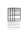
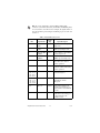
GETTING STARTED GUIDE
NI Digital Waveform
Generator/Analyzer
This document explains how to install, configure, test, and set up a National
Instruments digital waveform generator/analyzer. This document applies
specifically to the following devices:
• NI PXI/PCI-6541/6542 (NI 654X)
• NI PXI/PCI-6551/6552 (NI 655X)
• NI PXI-6561/6562 (NI 656X)
For more information about features and programming, refer to the
NI Digital Waveform Generator/Analyzer Help at Start»Programs»
National Instruments»NI-HSDIO»Documentation»
NI Digital Waveform Generator/Analyzer Help.
Refer to the specifications document that ships with your device for detailed
specifications.
For free downloads of the most current versions of product documentation
and example programs, visit ni.com/instruments.
Contents
Conventions ...............................................................................................2
1. Verifying the System Components ........................................................4
Minimum System Requirements .......................................................4
Recommended System.......................................................................4
2. Unpacking ..............................................................................................5
3. Verifying the Kit Contents.....................................................................6
Documentation...................................................................................6
EMI Gasket (NI PXI-655X Only) ......................................................6
4. Installing the Software ...........................................................................6
Choose and Install Your ADE ...........................................................6
Install NI-HSDIO...............................................................................7
(Optional) Install the NI Digital Waveform Editor ...........................7
January 2005
373308E-01
5. Installing the Hardware..........................................................................8
Installing a PXI Module.....................................................................8
Installing a PCI Device ......................................................................10
6. Configuring and Testing in MAX..........................................................11
Using the Test Panel to Generate and Acquire Data .........................12
7. Connecting Signals ................................................................................14
Connecting Cables and Accessories ..................................................14
Wiring for Common Measurements ..................................................16
8. Programming the Digital Waveform Generator/Analyzer.....................18
NI-HSDIO Instrument Driver ............................................................18
NI-HSDIO Examples .........................................................................18
Appendix A: Device Front Panels .............................................................18
Appendix B: Troubleshooting ...................................................................26
Technical Support Resources.....................................................................28
Conventions
The following conventions are used in this guide:
<>
Angle brackets that contain numbers separated by
an ellipsis represent a range of values associated
with a bit or signal name—for example,
DIO <3..0>.
»
The » symbol leads you through nested menu items
and dialog box options to a final action. The
sequence File»Page Setup»Options directs you to
pull down the File menu, select the Page Setup
item, and select Options from the last dialog box.
This icon denotes a tip, which alerts you to advisory
information.
This icon denotes a note, which alerts you to
important information.
This icon denotes a caution, which advises you of
precautions to take to avoid injury, data loss, or a
system crash. When this symbol is marked on the
product, refer to the Read Me First: Safety and
Radio-Frequency Interference document that
shipped with your device for precautions to take.
bold
Bold text denotes items that you must select or click
in the software, such as menu items and dialog box
options. Bold text also denotes parameter names.
NI Digital Waveform Generator/Analyzer Guide
2
ni.com
CompactPCI
CompactPCI refers to the core specification defined
by the PCI Industrial Computer Manufacturers
Group (PICMG).
italic
Italic text denotes variables, emphasis, or a cross
reference. This font also denotes text that is a
placeholder for a word or value that you must
supply.
monospace
Text in this font denotes text or characters that you
should enter from the keyboard, sections of code,
programming examples, and syntax examples. This
font is also used for the proper names of disk drives,
paths, directories, programs, subprograms,
subroutines, device names, functions, operations,
variables, filenames, and extensions.
monospace bold
Bold text in this font denotes the messages and
responses that the computer automatically prints to
the screen. This font also emphasizes lines of code
that are different from the other examples.
monospace italic
Italic text in this font denotes text that is a
placeholder for a word or value that you must
supply.
PCI
Peripheral Component Interconnect (PCI) is a
high-performance expansion bus architecture
originally developed by Intel to replace ISA
and EISA.
PXI
PCI eXtensions for Instrumentation (PXI) is a
rugged, open system for modular instrumentation
based on CompactPCI, with special mechanical,
electrical, and software features.
1. Verifying the System Components
This section specifies the minimum system requirements and recommended
system for NI-HSDIO and your digital waveform generator/analyzer.
Minimum System Requirements
The minimum system requirements include the following components
and tools:
• Pentium 200 MHz or equivalent processor
• 64 MB RAM
• A PXI chassis and controller or desktop computer
© National Instruments Corporation
3
NI Digital Waveform Generator/Analyzer Guide
•
•
•
•
•
•
1/8 in. flathead screwdriver
Number 1 Phillips screwdriver
Microsoft Internet Explorer 5.5 or later
Measurement & Automation Explorer (MAX) 3.1 or later
A screen resolution of 800 × 600 with 256 colors (required for the
NI Script Editor)
The appropriate cable for your device, as shown in the following table:
Table 1. NI Digital Waveform Generator/Analyzer Cables
Device
•
Cable
Cable Part Number
NI 654X
NI SHC68-C68-D2
188142-01
NI 655X
NI SHC68-C68-D2
188142-01
NI 656X
NI SHB12X-B12X
192344-01
NI EMC Filler Panel Kit, available from NI (part number 778700-01)
Recommended System
The recommended system requirements include the following components
and tools:
• Pentium III/Celeron 600 MHz or equivalent processor
• 256 MB RAM
• A PXI chassis and controller or desktop computer
• 1/8 in. flathead screwdriver
• Number 1 Phillips screwdriver
• Microsoft Internet Explorer 5.5 or later
• Measurement & Automation Explorer (MAX) 3.1 or later
• A screen resolution of 800 × 600 with 256 colors (required for the
NI Script Editor)
• The appropriate cable for your device, listed in Table 1.
• A compatible connectivity accessory for your NI digital waveform
generator/analyzer, listed in the following table:
Table 2. NI Digital Waveform Generator/Analyzer Accessories
Accessory
Supported Devices
NI CB-2162
NI 654X, NI 655X
NI SMB-2163
NI 654X, NI 655X
NI Digital Waveform Generator/Analyzer Guide
4
ni.com
•
•
Windows 2000/NT/XP, with all available critical updates and service
packs
One of the following application development environments (ADEs):
– LabVIEW 7.0 or later (LabVIEW 7.1 or later is required to use the
NI-HSDIO Express VIs)
– LabVIEW Real-Time Module 7.1
– LabWindows™/CVI™ 6.0 or later
– Microsoft Visual C++ (MSVC) 6.0 or later
2. Unpacking
The NI digital waveform generator/analyzer ships in an antistatic package to
prevent electrostatic discharge (ESD). ESD can damage several components
on the device.
Caution
Never touch the exposed pins of connectors.
To avoid ESD damage in handling the device, take the following precautions:
• Ground yourself with a grounding strap or by touching a grounded
object.
• Touch the antistatic package to a metal part of your computer chassis
before removing the device from the package.
Remove the device from the package and inspect it for loose components or
any other signs of damage. Notify NI if the device appears damaged in any
way. Do not install a damaged device in your computer or chassis.
Store the device in the antistatic package when the device is not in use.
3. Verifying the Kit Contents
Verify that the kit contains the following items:
❑
❑
❑
DVD-sized case, which contains the following items:
– NI-HSDIO (High-Speed Digital I/O) instrument driver software
CDs, which include the NI Digital Waveform Generator/Analyzer
Help
– NI Digital Waveform Generator/Analyzer Getting Started Guide
NI digital waveform generator/analyzer
Mounting screw (PCI devices only)
© National Instruments Corporation
5
NI Digital Waveform Generator/Analyzer Guide
❑
Other documentation included with the digital waveform
generator/analyzer and driver software. Refer to the Documentation
section for a list of the documentation you may have.
Documentation
The NI digital waveform generator/analyzer kit may also include the
following documents:
• NI digital waveform generator/analyzer specifications—This printed
document provides specifications for your device.
• Read Me First: Safety and Radio-Frequency Interference
• Maintain Forced-Air Cooling Note to Users
• Retrofitting Your PXI Module Note to Users
EMI Gasket (NI PXI-655X Only)
The NI PXI-655X kit also includes an EMI gasket and documentation that
describes under what conditions you should install the gasket. Refer to
step 5. Installing the Hardware for more information about the gasket.
4. Installing the Software
This section describes the software installation process for the NI digital
waveform generator/analyzer.
Choose and Install Your ADE
You can create applications for your digital waveform generator/analyzer
using LabVIEW 7.0 or later, LabWindows/CVI 6.0 or later, or Microsoft
Visual C++ 5.0 or later.
LabVIEW features interactive graphics, a state-of-the-art interface, and a
powerful graphical programming language. LabWindows/CVI is a complete
ANSI C ADE that features an interactive user interface, code generation
tools, and the LabWindows/CVI Data Acquisition and Easy I/O libraries.
Using LabVIEW or LabWindows/CVI can greatly reduce your application
development time.
If you have not already installed the ADE, follow the instructions in the
product documentation to install your ADE now.
NI Digital Waveform Generator/Analyzer Guide
6
ni.com
Install NI-HSDIO
NI-HSDIO features a set of operations and attributes that allow you to
programmatically configure and control the digital waveform
generator/analyzer. To install NI-HSDIO, complete the following steps:
1. Insert the first CD of the NI-HSDIO CD set. The NI-HSDIO installer
should open automatically. If not, select Start»Run, and enter
x:\setup.exe, where x is the letter of the CD drive.
2. Follow the instructions in the installation prompts. For troubleshooting
and operating system-specific instructions, refer to the Hardware
Installation Wizard at ni.com/support/install.
3. When the installer completes, a dialog box appears that asks if you want
to restart, shut down, or exit. Select Restart.
4. If you are using a system running the LabVIEW Real-Time Module,
download NI-HSDIO to the target using MAX. Refer to the
Measurement & Automation Explorer Remote Systems Help by selecting
Help»Help Topics»Remote Systems in MAX.
NI Script Editor
The NI Script Editor is included on the NI-HSDIO CD and is installed when
you install the driver. The NI Script Editor provides an intuitive interface
to help you develop linking and looping pattern generation operations.
NI Script Editor Help contains more information about the NI Script Editor.
You can access NI Script Editor Help by launching the NI Script Editor and
selecting Help»NI Script Editor Help from the toolbar.
(Optional) Install the NI Digital Waveform Editor
The NI Digital Waveform Editor (DWE) is included with the higher-memory
versions of NI digital waveform generator/analyzers and also can be
purchased separately at ni.com. The NI DWE allows you to easily import
data from popular third-party EDA programs, create your own waveforms,
edit these waveforms, and view acquired waveforms.
If you are using the NI DWE, install it after you install NI-HSDIO.
5. Installing the Hardware
To install your NI digital waveform generator/analyzer, follow the
instructions in the section that describes your hardware platform.
When installing your hardware, follow the instructions in this section to
ensure that your device can cool itself effectively. If the device temperature
rises above the optimal operating temperature range, the device disables
itself, and MAX or NI-HSDIO notifies you with an error message. For more
© National Instruments Corporation
7
NI Digital Waveform Generator/Analyzer Guide
information on re-enabling your device, refer to the I Received a Thermal
Shutdown Error section in Appendix B: Troubleshooting.
Installing a PXI Module
To install the module, refer to Figure 1 and complete the following steps:
1
4
NI
PX
3
I-1
04
2
2
1 PXI Chassis
2 Ejector Handle
3 Captive Screw
4 NI PXI Device
Figure 1. PXI Installation
1. Power down the chassis before installing the module.
2. If the chassis has multiple fan speed settings, ensure that the fans are set
to the highest setting. Do not set the fan speed to low or turn the fan off.
3. Position the chassis so that you allow plenty of space between the chassis
fan intake and exhaust vents. Blocking the fans affects the air flow
needed for cooling. For more information, refer to the chassis
documentation.
4. If you need to use an EMI gasket to reduce high-frequency emissions,
install it now. Refer to the Retrofitting Your PXI Module Note to Users
for gasket installation instructions.
5. Remove the packaging material on the PXI connector and on the screws.
6. Ensure that the ejector handle is in the unlatched (downward) position,
as shown in Figure 1.
NI Digital Waveform Generator/Analyzer Guide
8
ni.com
7. Holding the module by the ejector handle, slide it into an empty slot,
ensuring that the base card (on the left when looking at the front of the
module) engages with the card guides in the chassis.
8. Slide the module completely into the chassis and latch by pulling up on
the ejector handle.
9. Tighten the captive screws at the top and bottom of the module front
panel.
10. Before operating the module, install all chassis covers and filler panels.
Missing filler panels disrupt the necessary air circulation in the chassis.
Note NI recommends that you install slot blockers between
modules to maximize air flow. NI recommends using the PXI
Chassis Slot Blocker Kit, part number 778678-01, available for
purchase at ni.com.
NI PXI modules are sensitive instruments that should be handled carefully.
Do not expose the module to temperatures or humidity beyond the rated
maximums. Keep the module free of dust by cleaning with compressed air
only. Do not clean the module with any solvents or liquids. For more
information about module cooling, refer to the guidelines in the Maintain
Forced-Air Cooling Note to Users included with your NI digital waveform
generator/analyzer.
Maintaining PXI Systems
Clean the fan filters on the chassis regularly to prevent air circulation path
blockage. Cleaning frequency depends on the amount of use and the
operating environment. For specific information about cleaning procedures,
and other recommended maintenance, refer to the module specifications and
the chassis user documentation.
Uninstalling PXI Modules
When removing PXI modules from the chassis, first power down the chassis.
Then ensure that you are grounded with a grounding strap or are touching a
grounded metal surface. To avoid ESD, do not touch the exposed pins of the
PXI connector or any exposed circuitry on the module. When not in use, PXI
modules should be stored in the original antistatic packaging to avoid
damage.
During operation the metal surfaces of PXI modules may
become hot. Be careful when removing the module from the chassis
or when moving it to a different peripheral slot. When removing the
module, hold it by the ejector handle and front panel only.
Caution
© National Instruments Corporation
9
NI Digital Waveform Generator/Analyzer Guide
Installing a PCI Device
To install your PCI device, complete the following steps:
1. Power off and unplug the PC.
2. If the PC has multiple fan speed settings, ensure that the fans are set to
the highest setting.
3. Remove the PC cover.
4. Insert the device into an open PCI slot, as shown in Figure 2.
3
2
1
1 NI PCI Device
2 PCI Slot
3 Personal Computer
Figure 2. PCI Installation
NI recommends either leaving the slot adjacent to the fan side of the
device empty or using lower-profile devices in the slot adjacent to the
fan side.
5. Secure the device with the screw provided in the kit.
It is important to completely screw the device into the PCI
slot, both for mechanical stability and for creating a solid ground
connection, which reduces signal noise. Some computer
manufacturers use a plastic securing lever to secure PCI devices;
such a lever is unacceptable and must be removed, or you must use
Caution
NI Digital Waveform Generator/Analyzer Guide
10
ni.com
a different chassis. Improperly secured devices may affect the
accuracy of device specifications.
6. Before operating the device, install all filler panels. Missing filler panels
disrupt the necessary air circulation in the PC.
7. Replace the PC cover.
8. Plug in and power on the PC.
Maintaining PCI Systems
Inspect the onboard fan on a regular basis to prevent fan and air circulation
path blockage. Cleaning frequency depends on the amount of use and the
operating environment.
6. Configuring and Testing in MAX
To configure and test the NI digital waveform generator/analyzer in MAX,
complete the following steps:
1. Launch MAX to configure and test the digital waveform
generator/analyzer. MAX should automatically detect the device you
installed.
2. Expand Devices and Interfaces.
If you are using an NI digital waveform generator/analyzer with the
LabVIEW Real-Time Module, expand Remote Systems. Find your
target IP address or name, expand it, and then expand Devices and
Interfaces.
3. Expand NI-DAQmx Devices.
4. Check that your device appears under NI-DAQmx Devices.
Note If your device does not appear under NI-DAQmx Devices,
MAX did not detect the device, so you might need to refresh MAX
by selecting File»Refresh from the MAX menu or pressing <F5>.
5. You can perform a self-test on devices listed under NI-DAQmx Devices.
The self-test ensures that the device is installed correctly and can
communicate with NI-HSDIO. To perform a self-test, complete the
following steps:
a. Right-click the device you want to test and select Self-Test, shown
in Figure 3.
© National Instruments Corporation
11
NI Digital Waveform Generator/Analyzer Guide
Figure 3. Configuration Tree Shortcut Menu
b. When the self-test finishes, a message window appears to indicate if
an error occurred. If an error occurred, refer to ni.com/support
for troubleshooting information.
Tip If you need to reset the device with a hard reset, you can do so
by right-clicking the device and selecting Reset Device from the
shortcut menu shown in Figure 3.
6. Record the device name assigned to the digital device. You need this
information when you program the device.
Using the Test Panel to Generate and Acquire Data
To verify your device configuration, use the device test panel in MAX to
generate and acquire simple digital data using your device by completing the
following steps:
1. Right-click the device under NI-DAQmx Devices, and select Test Panels
as shown in Figure 3.
2. Click the Generation tab.
3. Select the Dynamic tab on the side of the pane.
4. Click Select All to select all of your channels. The digital pattern now
appears in the graph.
5. Enter the frequency in the Clock Frequency control, located on the left
side of the test panel.
NI Digital Waveform Generator/Analyzer Guide
12
ni.com
6. Enter values for the generation and acquisition voltages in the controls
below the Clock Frequency control. You can choose from standard logic
families (NI 654X/655X) or enter High and Low values to create your
own custom levels (NI 655X).
7. Choose a fill pattern. The following figure shows the pattern control and
the first few signals in the window.
Tip When generating a Marching Ones or Marching Zeroes
waveform, it is convenient to make the waveform size a multiple of
the number of selected channels.
8. Click Play to generate the pattern shown in the graph on the selected
channels. The default generation option is Continuous, but you can
toggle this setting using the control below the graph.
The Play and Stop buttons are shown in the following figure.
Because the data channels on the NI digital waveform generator/analyzer
are bidirectional, while the data is being continuously generated on all of
the channels, as in the previous step, you can acquire the data being
generated.
Refer to the specifications for your device for information on
the setup and hold times and propagation delays associated with
generation and acquisition operations. At some frequencies,
generating and acquiring data on the same channels when no cable
is attached to the DIGITAL DATA & CONTROL (DDC) connector
violates these timing parameters and results in incorrectly sampled
data. For information on proper signal acquisition, refer to the
NI Digital Waveform Generator/Analyzer Help.
Note
To acquire the pattern, complete the following steps:
1. Click the Acquisition tab.
2. Click Play. The device acquires the digital data that you generated in the
previous steps, and the data is displayed on the graph.
3. Click Close when you are finished.
© National Instruments Corporation
13
NI Digital Waveform Generator/Analyzer Guide
7. Connecting Signals
This section discusses what connections you can make to the device, and how
to connect signals to the device for performing dynamic acquisition and
dynamic generation. For device front panel diagrams and connector
descriptions, refer to Appendix A: Device Front Panels.
Connecting Cables and Accessories
To make connections to the NI digital waveform generator/analyzer front
panel SMB jack connectors, use a shielded 50 Ω coaxial cable with an SMB
plug end.
Use an NI SHC68-C68-D2 cable for connections to the NI 654X/655X DDC
connector. The NI SHC68-C68-D2 is designed for single-ended, high-speed
digital signal transmission. The cable is shielded, with individual
microcoaxial 50 Ω lines for each signal. Use an SHB12X-B12X cable for
connections to the NI 656X DDC connector. This cable is designed for
differential, high-speed digital signal transmission.
Using Accessories (NI 654X/655X Only)
NI recommends using the NI CB-2162 single-ended digital I/O accessory to
access the signals on the 68-pin DDC connector and to terminate the
DIO channels. The NI CB-2162 also provides a platform for circuit
prototyping and DUT testing. The NI CB-2162 is specifically designed for
use with single-ended NI digital waveform generator/analyzers
(NI 654X/655X). For more information about using the NI CB-2162, refer to
the NI CB-2162 User Guide.
NI also offers the NI SMB-2163 breakout box for National Instruments
single-ended digital waveform generator/analyzers. The NI SMB-2163 offers
coaxial SMB connectors for each channel on the DDC connector, providing
an easy way to connect to other devices for testing and debugging. For more
information about using the NI SMB-2163, refer to the NI SMB-2163 User
Guide.
Figures 4 and 5 show how to connect a single-ended NI digital waveform
generator/analyzer and the NI CB-2162 and NI SMB-2163, respectively,
using the NI SHC68-C68-D2 cable.
NI Digital Waveform Generator/Analyzer Guide
14
ni.com
2
NI PXI-1042
NI PXI-6551
50 MHz Digital I/O
ACCESS
ACTIVE
CLK
IN
PFI 0
CLK
OUT
DIGITAL DATA & CONTROL
J15
J5
J6
3
1
1 PXI Chassis with NI Digital Waveform
Generator/Analyzer
2 SHC68-C68-D2 Cable
3 NI CB-2162 Accessory
Figure 4. Connecting the NI CB-2162 Accessory
NI PXI-1042
NI PXI-6551
50 MHz Digital I/O
ACCESS
ACTIVE
CLK
IN
PFI 0
DIGITAL DATA & CONTROL
CLK
OUT
1
2
3
1 PXI Chassis with NI Digital Waveform
Generator/Analyzer
2 NI SMB-2163 Accessory
3 SHC68-C68-D2 Cable
Figure 5. Connecting the NI SMB-2163 Accessory
© National Instruments Corporation
15
NI Digital Waveform Generator/Analyzer Guide
Note If you are creating your own accessory to use with your
device, you can purchase the mating connector for the VHDCI
cable from NI (part number 778914-01).
Whether you use NI cables and accessories or design your own, you should
properly terminate cables to avoid improper measurements due to signal
reflections, overshoot, and undershoot. Refer to the NI Digital Waveform
Generator/Analyzer Help for more information about signal termination.
Wiring for Common Measurements
Dynamic generation and dynamic acquisition are two categories of
applications that you can create for NI digital waveform generator/analyzers.
This section provides information on the general wiring considerations for
each type of application. Both examples use the NI CB-2162 for signal
termination.
Dynamic Generation
When performing dynamic generation, an NI digital waveform
generator/analyzer generates data through a matched impedance system that
consists of a 50 Ω output impedance, a 50 Ω cable, and a 50 Ω accessory.
Figure 6 shows a diagram of such a system, using the NI 655X as an example.
Depending on the loading of the peripheral device, you may need additional
parallel termination resistance at the destination for optimal signal quality.
Refer to the NI Digital Waveform Generator/Analyzer Help for more
information about signal termination.
50
NI 655X
50
Peripheral
Device
Cable
NI CB-2162
Figure 6. Dynamic Generation Functional Diagram
NI Digital Waveform Generator/Analyzer Guide
16
ni.com
Dynamic Acquisition
When performing dynamic acquisition with the NI 654X/655X, the source
generating the signals needs a matched source impedance as close to 50 Ω as
possible to minimize signal reflections and maintain optimal signal quality.
Figure 7 shows a diagram of a dynamic acquisition system using the NI 655X
as an example.
RT
50
NI 655X
RS
Cable
Peripheral
Device
NI CB-2162
Figure 7. Dynamic Acquisition Functional Diagram
Note NI digital waveform generator/analyzers have various input
impedance settings, as shown in the following table.
Table 3. Supported Impedance Settings
Device
Supported Input Impedance
NI 654X
10 kΩ
NI 655X
50 Ω or 10 kΩ
NI 656X*
100 Ω for channels configured for
LVDS operation; 10 kΩ for channels
configured for single-ended operation
* NI 656X cables use 100 Ω differential impedance rather than 50 Ω single-ended
impedance.
Refer to the NI Digital Waveform Generator/Analyzer Help for more
information about signal termination.
© National Instruments Corporation
17
NI Digital Waveform Generator/Analyzer Guide
8. Programming the Digital Waveform
Generator/Analyzer
You can generate or acquire digital data with the NI digital waveform
generator/analyzer using NI-HSDIO. You also can run the NI-HSDIO
examples to demonstrate the functionality of your device.
NI-HSDIO Instrument Driver
The NI-HSDIO API features a set of operations and attributes that exercise
all the functionality of the device, including configuration, control, and other
device-specific functions.
Information about programming with NI-HSDIO is available in the
NI Digital Waveform Generator/Analyzer Help. This online document
contains hardware information, concepts, a detailed function/VI reference
for NI-HSDIO, and information specific to your device.
NI-HSDIO Examples
The NI-HSDIO examples demonstrate some of the functionality of the
NI digital waveform generator/analyzers that you can use or integrate into
your applications.
For the location of example programs that you can use as a basis for your
first NI-HSDIO program, refer to Programming»Getting Started with
NI-HSDIO in the NI Digital Waveform Generator/Analyzer Help.
Appendix A: Device Front Panels
This section contains front panel connector figures and connector description
tables that describe the signal connection options for NI digital waveform
generator/analyzers.
NI 654X/655X Front Panels and Connectors
The NI 654X/655X front panels contain four connectors—three SMB jacks
(CLK IN, PFI 0, and CLK OUT) and one 68-pin VHDCI connector
(DIGITAL DATA & CONTROL, or DDC).
Figure 8 shows the NI 6541 front panels and pinout, which are identical to
those of the NI 6542. The DDC signals are described in Table 4. The
SMB connectors are described in Table 7. The LEDs are described in
Tables 8 and 9.
NI Digital Waveform Generator/Analyzer Guide
18
ni.com
1
2
3
4
5
6
7
8
9
10
11
12
13
14
15
16
17
18
19
20
21
22
23
24
25
26
27
28
29
30
31
32
33
34
35
36
37
38
39
40
41
42
43
44
45
46
47
48
49
50
51
52
53
54
55
56
57
58
59
60
61
62
63
64
65
66
67
68
DIO 30
GND
DIO 28
GND
DIO 26
GND
DIO 24
GND
DIO 22
GND
DIO 20
GND
DIO 18
GND
DIO 16
GND
DIO 14
RESERVED
DIO 12
GND
DIO 10
GND
DIO 8
GND
DIO 6
RESERVED
DIO 4
GND
DIO 2
PFI 2
DIO 0
GND
STROBE
GND
NI PXI-6541
50 MHz Digital I/O
ACCESS
NI PCI-6541
CLK
IN
ACTIVE
PFI
0
CLK
IN
CLK
OUT
PFI 0
CLK
OUT
DIGITAL DATA & CONTROL
DIO 31
GND
DIO 29
GND
DIO 27
GND
DIO 25
RESERVED
DIO 23
GND
DIO 21
GND
DIO 19
GND
DIO 17
GND
DIO 15
GND
DIO 13
GND
DIO 11
GND
DIO 9
GND
DIO 7
PFI 1
DIO 5
GND
DIO 3
PFI 3
DIO 1
GND
DDC CLK OUT
GND
DIGITAL
DATA &
CONTROL
The Digital Data & Control connector pinout
is the same for PXI and PCI devices.
Figure 8. NI 654X Front Panel Connectors
© National Instruments Corporation
19
NI Digital Waveform Generator/Analyzer Guide
Table 4. NI 654X DDC Connector Pins
Pins
Signal
Name
Signal
Type
Signal Description
33
DDC CLK
OUT
Control
Output terminal for the exported
Sample clock.
67
STROBE
Control
Terminal for the external Sample clock
source which can be used for pattern
acquisition.
DIO <0..31> Data
Bidirectional digital I/O data channels
0 through 31.
26, 30, 64
PFI <1..3>
Control
Input terminals to the NI 654X for
external triggers, or output terminals
from the NI 654X for events.
2, 4, 6, 10, 12,
14, 16, 18, 20,
22, 24, 28, 32,
34, 36, 38, 40,
42, 44, 46, 48,
50, 54, 56, 58,
62, 66
GND
Ground
Ground reference for signals.
8, 52, 60
RESERVED
N/A
These terminals are reserved for future
use. Do not connect to these pins.
1, 3, 5, 7, 9,
11, 13, 15, 17,
19, 21, 23, 25,
27, 29, 31, 35,
37, 39, 41, 43,
45, 47, 49, 51,
53, 55, 57, 59,
61, 63, 65
NI Digital Waveform Generator/Analyzer Guide
20
ni.com
Figure 9 shows the NI 6551 front panels and pinout, which are identical to
those of the NI 6552. The DDC signals are described in Table 5. The SMB
connectors are described in Table 7. The LEDs are described in
Tables 8 and 9.
1
2
3
4
5
6
7
8
9
10
11
12
13
14
15
16
17
18
19
20
21
22
23
24
25
26
27
28
29
30
31
32
33
34
35
36
37
38
39
40
41
42
43
44
45
46
47
48
49
50
51
52
53
54
55
56
57
58
59
60
61
62
63
64
65
66
67
68
RESERVED
GND
RESERVED
GND
RESERVED
GND
RESERVED
GND
RESERVED
GND
RESERVED
GND
DIO 18
GND
DIO 16
GND
DIO 14
RESERVED
DIO 12
GND
DIO 10
GND
DIO 8
GND
DIO 6
RESERVED
DIO 4
GND
DIO 2
PFI 2
DIO 0
GND
STROBE
GND
NI PXI-6551
50 MHz Digital I/O
ACCESS
NI PCI-6551
CLK
IN
ACTIVE
PFI
0
CLK
IN
CLK
OUT
PFI 0
CLK
OUT
DIGITAL DATA & CONTROL
RESERVED
GND
RESERVED
GND
RESERVED
GND
RESERVED
RESERVED
RESERVED
GND
RESERVED
GND
DIO 19
GND
DIO 17
GND
DIO 15
GND
DIO 13
GND
DIO 11
GND
DIO 9
GND
DIO 7
PFI 1
DIO 5
GND
DIO 3
PFI 3
DIO 1
GND
DDC CLK OUT
GND
DIGITAL
DATA &
CONTROL
The Digital Data & Control connector pinout
is the same for PXI and PCI devices.
Figure 9. NI 655X Front Panel Connectors
© National Instruments Corporation
21
NI Digital Waveform Generator/Analyzer Guide
Table 5. NI 655X DDC Connector Pins
Pins
Signal
Name
Signal
Type
Signal Description
33
DDC CLK
OUT
Control
Output terminal for the exported
Sample clock.
67
STROBE
Control
Terminal for the external Sample clock
source which can be used for pattern
acquisition.
13, 15, 17, 19,
21, 23, 25, 27,
29, 31, 47, 49,
51, 53, 55, 57,
59, 61, 63, 65
DIO <0..19> Data
Bidirectional digital I/O data channels
0 through 19.
26, 30, 64
PFI <1..3>
Control
Input terminals to the NI 655X for
external triggers, or output terminals
from the NI 655X for events.
2, 4, 6, 10, 12,
14, 16, 18, 20,
22, 24, 28, 32,
34, 36, 38, 40,
42, 44, 46, 48,
50, 54, 56, 58,
62, 66
GND
Ground
Ground reference for signals.
1, 3, 5, 7, 8, 9,
11, 35, 37, 39,
41, 43, 45, 52,
60
RESERVED
N/A
These terminals are reserved for future
use. Do not connect to these pins.
NI 656X Front Panels and Connectors
The NI 656X front panels contain four connectors—three SMB jacks
(CLK IN, PFI 0, and CLK OUT) and one 73-pin 12x Infiniband connector
(DIGITAL DATA & CONTROL, or DDC).
Figure 10 shows the NI 6561 front panels and pinout, which are identical to
those of the NI 6562. Signals marked with an asterisk represent the
complementary terminal for the differential signal of the same name. The
DDC signals are described in Table 6. The SMB connectors are the same as
those described in Table 7, and the LEDs are the same as those described in
Tables 8 and 9.
Note If you are designing a custom cabling solution with connector
(779157-01) and cable (192744-01), the NI 656X pinout is reversed
at the end connector. For example, the signal shown on pin 1 shown
in the previous figure would map to pin 73 at the end connector.
NI Digital Waveform Generator/Analyzer Guide
22
ni.com
3
PFI_2*
6
PFI_3* / GND
RESERVED(NC)
DIO 0*
DIO 1*
DIO 2*
DIO 3*
DIO 4*
DIO 5*
DIO 6*
DIO 7*
DIO 8*
DIO 9*
DIO 10*
DIO 11*
DIO 12*
DIO 13*
DIO 14*
DIO 15*
STROBE*
DDC CLK OUT LVDS*
RESERVED(NC)
DDC CLK OUT LVPECL*
1
4
2
PFI_1
5
PFI_2
7
9 8
10
12 11
13
15 14
16
18 17
19
21 20
22
24 23
25
27 26
28
30 29
31
33 32
34
36 35
37
39 38
40
42 41
43
45 44
46
48 47
49
51 50
52
54 53
55
57 56
58
60 59
61
63 62
64
66 65
67
69 68
70
72 71
73
PFI_3
GND
GND
GND
GND
RESERVED(NC)
GND
DIO 0
GND
DIO 1
GND
DIO 2
GND
DIO 3
GND
DIO 4
GND
DIO 5
GND
DIO 6
GND
DIO 7
GND
DIO 8
GND
DIO 9
GND
DIO 10
GND
DIO 11
GND
DIO 12
GND
DIO 13
GND
DIO 14
GND
DIO 15
GND
STROBE
GND
DDC CLK OUT LVDS
GND
RESERVED(NC)
GND
DDC CLK OUT LVPECL
GND
NI PXI-6561
100 MHz LVDS DIO
ACCESS
ACTIVE
CLK
IN
PFI 0
CLK
OUT
DIGITAL DATA & CONTROL
PFI_1*
Figure 10. NI 656X Front Panel Connectors
© National Instruments Corporation
23
NI Digital Waveform Generator/Analyzer Guide
If you are designing a custom cabling solution with
connector (779157-01) and cable (192744-01), the NI665X pinout
is reversed at the end connector. For example, the signal shown on
pin 1 shown in the previous figure would map to pin 73 at the end
connector.
Note
Table 6. NI 656X DDC Connector Pins
Pins
Signal Name
Signal
Type
Signal Description
65
DDC CLK OUT
LVDS
Control
Positive terminal for the exported
Sample clock.
66
DDC CLK OUT
LVDS*
Control
Complementary terminal for the
LVDS exported Sample clock.
71
DDC CLK OUT
LVPECL
Control
Positive terminal for the LVPECL
exported Sample clock.
72
DDC CLK OUT
LVPECL*
Control
Complementary terminal for the
LVPECL exported Sample clock.
62
STROBE
Control
Positive external Sample clock
source which can be used for
dynamic acquisition.
63
STROBE*
Control
Complementary external Sample
clock source which can be used for
dynamic acquisition.
14, 17, 20, 23,
26, 29, 32, 35,
38, 41, 44, 47,
50, 53, 56, 59
DIO <0..15>
Data
Bidirectional digital I/O data
channels 0 through 15.
15, 18, 21, 24,
27, 30, 33, 36,
39, 42, 45, 48,
51, 54, 57, 60
DIO <0..15>*
Data
Complementary bidirectional
digital I/O data channels
0 through 15.
2, 5, 8
PFI<1..3>
Control
Positive input terminals to the
NI 656X for external triggers, or
output terminals from the NI 656X
for events.
3, 6, 9
PFI<1..3>*
Control
Complementary input terminals to
the NI 656X for external triggers,
or output terminals for the
NI 656X for events.
NI Digital Waveform Generator/Analyzer Guide
24
ni.com
Table 6. NI 656X DDC Connector Pins (Continued)
Pins
Signal
Type
Signal Name
Signal Description
1, 4, 7, 10, 13,
16, 19, 22, 25,
28, 31, 34, 37,
40, 43, 46, 49,
52, 55, 58
GND
Ground
Ground reference for signals.
11, 12, 68, 69
RESERVED
N/A
These terminals are reserved for
future use. Do not connect to
these pins.
Table 7. NI 654X/655X/656X SMB Connectors
Connector
Signal
Name
Signal
Type
Description
CLK IN
Reference/
Clock Input
Control
Terminal for the external Reference
clock used for the PLL or for the
external Sample clock used for
pattern generation and/or
acquisition.
PFI 0
Programmable
Function
Interface
(PFI) 0
Control
Input terminal to the device for
external triggers, or output terminal
from the device for events.
CLK OUT
Reference/
Clock Output
Control
Terminal for the exported PLL
Reference clock or the exported
Sample clock.
Tables 8 and 9 describe the different conditions indicated by the two
NI PXI LEDs.
Table 8. ACTIVE LED Indicators
Color
Indications
Off
Device not armed, not triggered, or experiencing an error.
Amber
Device armed and awaiting Start trigger. If performing a
dynamic acquisition operation, the device may be acquiring
pretrigger samples.
Green
Device received Start trigger.
Red
Error condition.
© National Instruments Corporation
25
NI Digital Waveform Generator/Analyzer Guide
Table 9. ACCESS LED Indicators
Color
Indications
Off
Device not ready.
Amber
Device being accessed by software.
Green
Device ready to be programmed.
Red
Running the niHSDIO Self Test VI or calling
niHSDIO_self_test produced a failure.
Appendix B: Troubleshooting
Device Front Panel ACCESS LED on PXI Module is Off
When PXI Chassis is On
If the ACCESS LED is not lit after you power on the PXI chassis, a problem
may exist with the PXI power rails, a hardware device, or the LED.
Note The LEDs may not light until the device has been configured
in MAX. Before troubleshooting this issue, verify that the device
appears in MAX.
Troubleshoot this issue by completing the following steps:
1. Power off your PXI chassis.
2. Disconnect any signals from the PXI module front panel.
3. Remove the PXI module and inspect for signs of damage. Do not reinstall
a damaged device.
4. Reinstall the PXI module using the procedure described in
step 5. Installing the Hardware.
5. Power on your PXI chassis.
6. Verify the device appears in MAX.
7. Reset the device in MAX and perform a self-test. Refer to
step 6. Configuring and Testing in MAX for information on performing
device resets and self-tests in MAX.
8. If the ACCESS LED still fails to light, contact NI support at
ni.com/support.
NI Digital Waveform Generator/Analyzer Guide
26
ni.com
Device Does Not Appear in MAX
Complete the following steps if the NI device does not appear in MAX:
1. In the MAX Configuration pane, click Devices and Interfaces to expand
the category.
2. Click NI-DAQmx Devices and press <F5> to refresh the list of installed
devices.
3. If the device is still not listed, power down the system, ensure the device
is correctly installed, and restart.
4. If the device still does not appear under NI-DAQmx Devices, contact
NI support at ni.com/support.
Device Failed the Self-Test
The MAX self-test performs a brief test of device resources. If the device
does not pass the self-test, complete the following steps:
1. Reboot your system.
2. Launch MAX and perform the self-test again. If the device still fails the
self-test, proceed to step 3.
3. Uninstall and reinstall NI-HSDIO.
4. If the device still fails the self-test, contact NI support at ni.com/
support.
I Received a Thermal Shutdown Error
I received the kErrorDeviceShutDownDueToHighTemp error, and my
device shut down. What should I do next?
To re-enable your device after a thermal shutdown, you must perform a hard
reset, in which the device integrated circuits (ICs) are reloaded. To re-enable
your device after thermal shutdown, complete the following steps:
1. Power down the computer or chassis that contains the device.
2. Review the procedure in step 5. Installing the Hardware and make any
necessary adjustments to ensure that your device is effectively cooled.
3. Call niHSDIO_ResetDevice (NI-HSDIO Reset Device VI) or perform
a device reset in MAX. For more information on performing a device
reset in MAX, refer to step 6. Configuring and Testing in MAX.
The thermal shutdown error continues to be reported until the device has
been successfully reset.
© National Instruments Corporation
27
NI Digital Waveform Generator/Analyzer Guide
Performance Issues Using MXI Connection
When using a MXI connection to control the PXI chassis, the MXI
Optimization Application must be run prior to using the NI device.
By default, this application runs automatically when Windows starts. Use of
a MXI connection without running this application may result in a time
exceeded or internal software error, or an initialization, timeout, or
performance issue when using the NI device.
If you are experiencing errors and are uncertain whether the MXI
Optimization Application ran, navigate to Start»Programs»National
Instruments MXI and select MXI Optimization to run the application.
If the application is not installed, refer to the software CD included with the
MXI kit to install the software. After installation, you may be required to
reboot the computer before using the MXI Optimization Application.
If you continue to have initialization or performance issues, refer to the
MXI documentation at Start»Programs»National Instruments MXI, or
visit NI Technical Support at ni.com/support.
Technical Support Resources
NI Web Support
The National Instruments Web site is your complete resource for technical
support. At ni.com/support you have access to everything from
troubleshooting and application development self-help resources to email
and phone assistance from NI Application Engineers.
A Declaration of Conformity (DoC) is our claim of compliance with the
Council of the European Communities using the manufacturer’s declaration
of conformity. This system affords the user protection for electronic
compatibility (EMC) and product safety. You can obtain the DoC for your
product by visiting ni.com/certification. If your product supports
calibration, you can obtain the calibration certificate for your product at
ni.com/calibration.
Worldwide Support
National Instruments corporate headquarters is located at
11500 North Mopac Expressway, Austin, Texas, 78759-3504.
National Instruments also has offices located around the world to help
address your support needs. For telephone support in the United States, create
NI Digital Waveform Generator/Analyzer Guide
28
ni.com
your service request at ni.com/support and follow the calling instructions
or dial 512 795 8248. For telephone support outside the United States,
contact your local branch office:
Australia 1800 300 800, Austria 43 0 662 45 79 90 0,
Belgium 32 0 2 757 00 20, Brazil 55 11 3262 3599,
Canada (Calgary) 403 274 9391, Canada (Ottawa) 613 233 5949,
Canada (Québec) 450 510 3055, Canada (Toronto) 905 785 0085,
Canada (Vancouver) 604 685 7530, China 86 21 6555 7838,
Czech Republic 420 224 235 774, Denmark 45 45 76 26 00,
Finland 385 0 9 725 725 11, France 33 0 1 48 14 24 24,
Germany 49 0 89 741 31 30, India 91 80 51190000, Israel 972 0 3 6393737,
Italy 39 02 413091, Japan 81 3 5472 2970, Korea 82 02 3451 3400,
Malaysia 603 9131 0918, Mexico 01 800 010 0793,
Netherlands 31 0 348 433 466, New Zealand 0800 553 322,
Norway 47 0 66 90 76 60, Poland 48 22 3390150,
Portugal 351 210 311 210, Russia 7 095 783 68 51,
Singapore 65 6226 5886, Slovenia 386 3 425 4200,
South Africa 27 0 11 805 8197, Spain 34 91 640 0085,
Sweden 46 0 8 587 895 00, Switzerland 41 56 200 51 51,
Taiwan 886 2 2528 7227, Thailand 662 992 7519,
United Kingdom 44 0 1635 523545
© National Instruments Corporation
29
NI Digital Waveform Generator/Analyzer Guide
National Instruments, NI, ni.com, and LabVIEW are trademarks of National Instruments Corporation. Refer to the Terms of Use section
on ni.com/legal for more information about National Instruments trademarks. Other product and company names mentioned
herein are trademarks or trade names of their respective companies. For patents covering National Instruments products, refer to the
appropriate location: Help»Patents in your software, the patents.txt file on your CD, or ni.com/patents.
© 2003–2005 National Instruments Corp. All rights reserved.