1
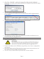
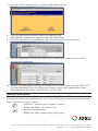
JDSU ONT-601 MTM Quick Start Guide Version 1.2 This guide will assist you with the initial configuration of your ONT-601 MTM to have you up and running in minutes. For further details on the initial setup and use of your ONT product, please refer to the ONT-601 MTM user manual. What you need to start • An external PC running Java version 6.0. • A network LAN connection for the PC and MTM, or alternatively an Ethernet cable for direct connection. The MTM has an auto-sensing LAN port, so a straight-through or crossover cable will both operate correctly. • The MTM connected to a power source using AC power cord compatible for your area. Note that a power cord is shipped with every new unit from the factory. Minimum PC system requirements ONT-601 MTM operation requires the following minimum requirements for the user PC: • Microsoft Windows XP, Vista, or Windows 7, or alternatively an equivalent Linux environment • Pentium 4 1500MHz, or equivalent with 512M of RAM (OS may require faster processor) • LAN connection capability • One of the following Internet browsers: Microsoft Internet Explorer 6.0 or higher, or Mozilla Firefox 3.0 or higher • Java Runtime Environment (JRE) Plug-in Version 6.0 (1.6.x) Installation of optical interfaces Install an SFP and/or XFP into each port that you will be using on the MTM. Enabled V15.x 2 1 4s4x Test Clock CPU Pwr IP Fault Standby Reset Enabled V15.x SFP XFP Lsr On Rx Lsr On 3 SFP XFP Rx Lsr On Rx Lsr On 4 SFP XFP Rx Lsr On Rx Lsr On SFP XFP Rx Lsr On Rx Lsr On Rx LAN OPR USB Note: For Software V1.x, only XFP ports 1 and 3 are enabled. No SFP ports. For Software V15.x, only XFP/SFP port 1 and 3 are enabled. LAN connection and configuration Select one of the following methods to connect and configure the MTM for LAN communication. Direct to PC connection Use this method when connection is direct to a local PC. 1. Connect a RJ-45 Ethernet cable from the MTM faceplate Ethernet port to your PC LAN port. 2. Power on the MTM and wait for the CPU light to start flashing. 3. If you received the MTM new from the factory, you may skip this step. Depress the recessed black IP reset button (highlighted within the white box on page 2) with a paper clip, ball point pen, or similar instrument until the red LED illuminates, and hold for a minimum of 2 seconds. Ensure to only depress the button until it reaches the end of its travel to avoid damage to the switch. This will set the ONT-601 MTM to its default IP address 192.168.0.101. This default address is only valid until the next re-boot of the unit. After re-boot, the Page 1 www.jdsu.com/test ONT‑601 MTM will either look for a DHCP assigned address, or default to its fixed address (see next chapters). 4. On your PC, configure the following network settings: • IP Address: 192.168.0.100 • Subnet mask: 255.255.255.0 • Default gateway: 192.168.0.1 Existing LAN Infrastructure - DHCP assigned addressing Use this method to assign the MTM IP address using a DHCP server. The MTM is shipped from the factory for this type of connection. 1. Connect an RJ-45 cable from the MTM faceplate Ethernet port to your network hub or remote jack. 2. Power on the MTM, and a DHCP request is issued on boot-up. If the MTM has already been powered on, you may depress the recessed black IP reset button (highlighted within the white box below) with a paper clip, ball point pen, or similar instrument until the red LED illuminates and hold for a minimum of 2 seconds. Ensure to only depress the button until it reaches the end of its travel to avoid damage to the switch. 3. Verify the IP address and netmask have been correctly assigned by checking the LCD display on the front panel. Note: If the default IP address 192.168.0.101 is shown on the LCD display, then the DHCP server is not available or there was a LAN issue that prevented the MTM from acquiring a DHCP address from the server. If this happens, try rebooting the MTM, try using the Static IP procedure instead, or consult with your network administrator. Existing LAN Infrastructure - Static IP Use this method when a static IP address will be assigned to MTM. Note that the IP address must be unique for your network (i.e. not in use by another device) to avoid any conflict. Please consult your network administrator if necessary. 1. Go through all of the steps described in “Direct to PC Connection” or “Existing LAN infrastructure - DHCP assigned addressing”, depending on which of the two apply to your setup. 2. Go through the steps described in “Connecting and using the GUI system” on page 3 until you see the “Welcome to ONT-601 MTM 4s4x” page. 3. Now select Launch ONT Scout link in order to get access to the IP setup function. Page 2 4. Select View > Find ONT..., and enter the range of the subnet currently configured. Entering the start address will automatically fill in the end address based on the IP subnetmask used. 5. Select the module configuration button for the MTM. You are prompted for the Administrator password. This password is Administrator by factory default. 6. Enter the new IP address information required for your network. 7. Select OK. If you used the “Direct to PC Connection” method, the MTM may be connected back into your LAN infrastucture. Connecting and using the GUI System 1. Open your internet browser. ATTENTION The web browser that you use to display the MTM GUI maintains a cache of recently-accessed web pages. It may be necessary to manually clear the cached files before launching the Application GUI. 2. Exclude the IP address of the MTM from using the Proxy Server if one is configured for your browser. 3. Enter the IP address of the MTM to which you want to connect into your browser’s address field to run the Java Applet and launch the GUI. 4. Select the “Accept” button if you are presented with a security certificate. Page 3 5. Once the GUI is displayed, select Launch Application GUI link. 6. Select the port that you wish to connect to, and select OK. 7. Highlight New-Application, and then select the Load button. 8. Select the Signal Structure pull-down, and select the protocols you wish to test. 9. Once the application is loaded, you will receive a control panel which has each of the protocol layers displayed. 10. The Laser is turned off on start-up. The Alarm status is shown on the left side of the GUI. Selecting individual Layer tabs will present various chapters for Configuration, Status, Alarm and Error Injections, and other Layer specific tools. Questions or Problems? Please refer to the User Manuals that are installed on the ONT-601 MTM or available via the Help tab on each layered protocol on the GUI. If you still require assistance, please contact the JDSU Technical Assistance Center. Americas: 1-866-228-3762, Option 3, Option 1 EMEA and APAC: +49 7121 86 1345 Americas: [email protected] EMEA and APAC: [email protected] Product specifications and descriptions in this document are subject to change without notice. © 2011 JDS Uniphase Corporation 21162407-003 1211 ONT-601MTM.QC.OPT.TM.AE