1
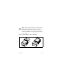
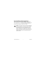
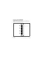
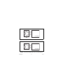
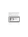
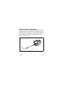
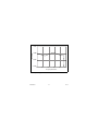
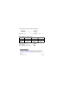
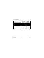
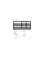
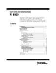
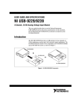
OPERATING INSTRUCTIONS AND SPECIFICATIONS NI 9229/9239 4-Channel, ±60/±10 V, 24-Bit Simultaneous, Channel-to-Channel Isolated Analog Input Modules Français Deutsch ni.com/manuals This document describes how to use the National Instruments 9229 and National Instruments 9239 and includes specifications and terminal assignments. In this document, the NI 9229 and NI 9239 are referred to inclusively as the NI 9229/9239. Visit ni.com/info and enter rdsoftwareversion to determine which software you need for the modules you are using. For information about installing, configuring, and programming the system, refer to the system documentation. Visit ni.com/info and enter cseriesdoc for information about C Series documentation. Note The safety guidelines and specifications in this document are specific to the NI 9229/9239. The other components in the system might not meet the same safety ratings and specifications. Refer to the documentation for each component in the system to determine the safety ratings and specifications for the entire system. Visit ni.com/info and enter cseriesdoc for information about C Series documentation. NI 9229/9239 2 ni.com Safety Guidelines Operate the NI 9229/9239 only as described in these operating instructions. This icon denotes that the component may be hot. Touching this component may result in bodily injury. Hot Surface Safety Guidelines for Hazardous Voltages If hazardous voltages are connected to the module, take the following precautions. A hazardous voltage is a voltage greater than 42.4 Vpk or 60 VDC to earth ground. Ensure that hazardous voltage wiring is performed only by qualified personnel adhering to local electrical standards. Caution Caution Do not mix hazardous voltage circuits and human-accessible circuits on the same module. Make sure that devices and circuits connected to the module are properly insulated from human contact. Caution © National Instruments Corp. 3 NI 9229/9239 When module terminals are hazardous voltage LIVE (>42.4Vpk/60 VDC), you must ensure that devices and circuits connected to the module are properly insulated from human contact. You must use the NI 9971 connector backshell kit to ensure that the terminals are not accessible. Caution Figure 1 shows the NI 9971 connector backshell. Figure 1. NI 9971 Connector Backshell NI 9229/9239 4 ni.com Safety Guidelines for Hazardous Locations The NI 9229/9239 is suitable for use in Class I, Division 2, Groups A, B, C, D, T4 hazardous locations; Class I, Zone 2, AEx nA IIC T4, and Ex nA IIC T4 hazardous locations; and nonhazardous locations only. Follow these guidelines if you are installing the NI 9229/9239 in a potentially explosive environment. Not following these guidelines may result in serious injury or death. Caution Do not disconnect I/O-side wires or connectors unless power has been switched off or the area is known to be nonhazardous. Do not remove modules unless power has been switched off or the area is known to be nonhazardous. Caution Substitution of components may impair suitability for Class I, Division 2. Caution For Zone 2 applications, install the system in an enclosure rated to at least IP 54 as defined by IEC 60529 and EN 60529. Caution © National Instruments Corp. 5 NI 9229/9239 For Zone 2 applications, install a protection device between the input signal and the NI 9229/9239 input terminal. The device must prevent the input channel-to-COM voltage from exceeding 85 V if there is a transient overvoltage condition. Caution Caution For Zone 2 applications, connected signals must be within the following limit: Capacitance .......................... 0.01 μF max Special Conditions for Hazardous Locations Use in Europe This equipment has been evaluated as Ex nA IIC T4 equipment under DEMKO Certificate No. 07 ATEX 0626664X. Each module is marked II 3G and is suitable for use in Zone 2 hazardous locations. If you are using the NI 9229/9239 in Gas Group IIC hazardous locations or in ambient temperatures of –40 °C ≤ Ta ≤ 70 °C, you must use the device in an NI chassis that has been evaluated as EEx nC IIC T4, Ex nA IIC T4, or Ex nL IIC T4 equipment. NI 9229/9239 6 ni.com Special Conditions for Marine Applications Some modules are Lloyd’s Register (LR) Type Approved for marine applications. To verify Lloyd’s Register certification, go to ni.com/certification and search for the LR certificate, or look for the Lloyd’s Register mark on the module. To meet radio frequency emission requirements for marine applications, use shielded cables and install the system in a metal enclosure. Suppression ferrites must be installed on power supply inputs near power entries to modules and controllers. Power supply and module cables must be separated on opposite sides of the enclosure and must enter and exit through opposing enclosure walls. Caution © National Instruments Corp. 7 NI 9229/9239 Connecting the NI 9229/9239 The NI 9229/9239 provides connections for four simultaneously sampled, isolated analog input channels. AI0+ AI0– 0 1 AI1+ AI1– 0 1 AI2+ AI2– 0 1 AI3+ AI3– 0 1 Figure 2. NI 9229/9239 Terminal Assignments NI 9229/9239 8 ni.com The NI 9229/9239 has four 2-terminal detachable screw-terminal connectors. You must use 2-wire ferrules to create a secure connection when connecting more than one wire to a single terminal on the NI 9229/9239. Note You can connect ground-referenced or floating signal sources to the NI 9229/9239. Connect the positive signal of the signal source to the AI+ terminal or connector, and connect the negative signal of the signal source to the AI– terminal or connector. If you make a ground-referenced connection between the signal source and the NI 9229/9239, make sure the voltage on the AI+ and AI– connections are in the channel-to-earth safety voltage range to ensure proper operation of the NI 9229/9239. Refer to the Specifications section for more information about operating voltages and overvoltage protection. Refer to Figures 3 and 4 for illustrations of how to connect grounded and floating signal sources to the NI 9229/9239. © National Instruments Corp. 9 NI 9229/9239 Signal Source + – AI+ AI– NI 9229/9239 Figure 3. Connecting a Grounded Signal Source to the NI 9229/9239 Signal Source AI+ + – AI– NI 9229/9239 Figure 4. Connecting a Floating Signal Source to the NI 9229/9239 NI 9229/9239 10 ni.com The NI 9229/9239 analog input channels are floating with respect to earth ground and each other. The incoming analog signal on each channel is conditioned, buffered, and then sampled by a 24-bit Delta-Sigma ADC. Each channel provides an independent signal path and ADC, enabling you to sample all four channels simultaneously. Refer to Figure 5 for an illustration of the circuitry for one channel. AI+ AI– Overvoltage Protection ADC Amplifier Prefilter NI 9229/9239 Figure 5. Input Circuitry for One Channel of the NI 9229/9239 © National Instruments Corp. 11 NI 9229/9239 Wiring for High-Vibration Applications If an application is subject to high vibration, National Instruments recommends that you either use ferrules to terminate wires to the detachable screw-terminal connector or use the NI 9971 backshell kit to protect the connections. Refer to Figure 6 for an illustration of using ferrules. Refer to Figure 1 for an illustration of the NI 9971 connector backshell. Figure 6. 2-Terminal Detachable Screw-Terminal Connector with Ferrule NI 9229/9239 12 ni.com Understanding NI 9229/9239 Filtering The NI 9229/9239 uses a combination of analog and digital filtering to provide an accurate representation of in-band signals while rejecting out-of-band signals. The filters discriminate between signals based on the frequency range, or bandwidth, of the signal. The three important bandwidths to consider are the passband, the stopband, and the alias-free bandwidth. The NI 9229/9239 represents signals within the passband, as quantified primarily by passband flatness and phase nonlinearity. All signals that appear in the alias-free bandwidth are either unaliased signals or signals that have been filtered by at least the amount of the stopband rejection. Passband The signals within the passband have frequency-dependent gain or attenuation. The small amount of variation in gain with respect to frequency is called the passband flatness. The digital filters of the NI 9229/9239 adjust the frequency range of the passband to match the data rate. Therefore, the amount of gain or attenuation at a given frequency depends on the data rate. Figure 7 shows typical passband flatness for the NI 9229/9239. © National Instruments Corp. 13 NI 9229/9239 0.025 Gain (dB) 0.000 –0.025 –0.050 0 0.1 0.2 0.3 0.4 0.5 Frequency/Data Rate Figure 7. Typical Passband Flatness for the NI 9229/9239 NI 9229/9239 14 ni.com Stopband The filter significantly attenuates all signals above the stopband frequency. The primary goal of the filter is to prevent aliasing. Therefore, the stopband frequency scales precisely with the data rate. The stopband rejection is the minimum amount of attenuation applied by the filter to all signals with frequencies within the stopband. Alias-Free Bandwidth Any signal that appears in the alias-free bandwidth of the NI 9229/9239 is not an aliased artifact of signals at a higher frequency. The alias-free bandwidth is defined by the ability of the filter to reject frequencies above the stopband frequency and equals the data rate minus the stopband frequency. Understanding NI 9229/9239 Data Rates The frequency of a master timebase (fM) controls the data rate (fs) of the NI 9229/9239. The NI 9229/9239 includes an internal master timebase with a frequency of 12.8 MHz, but the module also can accept an external master timebase or export its own master timebase. To synchronize the data rate of an NI 9229/9239 with other modules that use master timebases to control sampling, all of © National Instruments Corp. 15 NI 9229/9239 the modules must share a single master timebase source. Refer to the software help for information about configuring the master timebase source for the NI 9229/9239. Visit ni.com/info and enter cseriesdoc for information about C Series documentation. The following equation provides the available data rates of the NI 9229/9239: f M ÷ 256 fs = --------------------n where n is any integer from 1 to 31. However, the data rate must remain within the appropriate data rate range. Refer to the Specifications section for more information about the data rate range. When using the internal master timebase of 12.8 MHz, the result is data rates of 50 kS/s, 25 kS/s, 16.67 kS/s, and so on down to 1.613 kS/s, depending on the value of n. When using an external timebase with a frequency other than 12.8 MHz, the NI 9229/9239 has a different set of data rates. Note The cRIO-9151 R Series Expansion chassis does not support sharing timebases between modules. NI 9229/9239 16 ni.com Sleep Mode This module supports a low-power sleep mode. Support for sleep mode at the system level depends on the chassis that the module is plugged into. Refer to the chassis manual for information about support for sleep mode. If the chassis supports sleep mode, refer to the software help for information about enabling sleep mode. Visit ni.com/info and enter cseriesdoc for information about C Series documentation. Typically, when a system is in sleep mode, you cannot communicate with the modules. In sleep mode, the system consumes minimal power and may dissipate less heat than it does in normal mode. Refer to the Specifications section for more information about power consumption and thermal dissipation. © National Instruments Corp. 17 NI 9229/9239 Specifications The following specifications are typical for the range –40 to 70 °C unless otherwise noted. All voltages are relative to the AI– signal on each channel unless otherwise noted. The specifications are the same for the NI 9229 and the NI 9239 unless otherwise noted. Input Characteristics Number of channels.......................... 4 analog input channels ADC resolution................................. 24 bits Type of ADC..................................... Delta-Sigma (with analog prefiltering) Sampling mode ................................. Simultaneous Internal master timebase (fM) Frequency ................................... 12.8 MHz Accuracy..................................... ±100 ppm max Data rate range (fs) using internal master timebase Minimum.................................... 1.613 kS/s Maximum ................................... 50 kS/s NI 9229/9239 18 ni.com Data rate range (fs) using external master timebase Minimum.................................... 390.625 S/s Maximum ................................... 51.2 kS/s f M ÷ 256 Data rates1 (fs) ................................... --------------------- , n = 1, 2, …, 31 n Input voltage ranges (AI+ to AI–)2 Module Nominal (V) Typical (V) Minimum (V) NI 9229 ±60 ±62.64 ±61.5 NI 9239 ±10 ±10.52 ±10.3 Overvoltage protection ..................... ±100 V Input coupling................................... DC Input impedance (AI+ to AI–) .......... 1 MΩ 1 The data rate must remain within the appropriate data rate range. Refer to the Understanding NI 9229/9239 Data Rates section for more information. 2 Refer to the Safety Guidelines section for more information about safe operating voltages. © National Instruments Corp. 19 NI 9229/9239 Accuracy, NI 9229 Percent of Reading (Gain Error) Percent of Range* (Offset Error) Calibrated max (–40 to 70 °C) ±0.13% ±0.05% Calibrated typ (25 °C, ±5 °C) ±0.03% ±0.008% Uncalibrated max (–40 to 70 °C) ±1.2% ±0.55% Uncalibrated typ (25 °C, ±5 °C) ±0.3% ±0.11% Measurement Conditions * Range equals 62.64 V NI 9229/9239 20 ni.com Accuracy, NI 9239 Percent of Reading (Gain Error) Percent of Range* (Offset Error) Calibrated max (–40 to 70 °C) ±0.13% ±0.06% Calibrated typ (25 °C, ±5 °C) ±0.03% ±0.008% Uncalibrated max (–40 to 70 °C) ±1.4% ±0.70% Uncalibrated typ (25 °C, ±5 °C) ±0.3% ±0.11% Measurement Conditions * Range equals 10.52 V Input noise NI 9229....................................... 320 μVrms NI 9239....................................... 70 μVrms Stability Gain drift .................................... ±5 ppm/°C Offset drift NI 9229 ................................ ±150 μV/°C NI 9239 ................................ ±26 μV/°C © National Instruments Corp. 21 NI 9229/9239 Post calibration gain match (ch-to-ch, 20 kHz)............................. 0.22 dB max Crosstalk (1 kHz).............................. –130 dB Phase mismatch (ch-to-ch) NI 9229....................................... 0.045°/kHz max NI 9239....................................... 0.075°/kHz max Phase mismatch (module-to-module, max) NI 9229....................................... 0.045°/kHz + 360°· fin/fM NI 9239....................................... 0.075°/kHz + 360°· fin/fM Phase nonlinearity (fs = 50 kS/s) ....... 0.11° max Input delay NI 9229....................................... 38.4/fs + 2.6 μs NI 9239....................................... 38.4/fs + 3 μs Passband Frequency ................................... 0.453 · fs Flatness (fs = 50 kS/s) ................. ±100 mdB max Stopband Frequency ................................... 0.547 · fs Rejection..................................... 100 dB NI 9229/9239 22 ni.com Alias-free bandwidth ........................ 0.453 · fs –3 dB prefilter bandwidth (fs = 50 kS/s)...................................... 24.56 kHz CMRR (fin = 60 Hz) NI 9229....................................... 116 dB NI 9239....................................... 126 dB SFDR (1 kHz, –60 dBFS)................. –128 dBFS Total Harmonic Distortion (THD) 1 kHz, –1 dBFS .......................... –99 dB 1 kHz, –20 dBFS ........................ –105 dB MTBF ............................................... 662,484 hours at 25 °C; Bellcore Issue 2, Method 1, Case 3, Limited Part Stress Method Note Contact NI for Bellcore MTBF specifications at other temperatures or for MIL-HDBK-217F specifications. © National Instruments Corp. 23 NI 9229/9239 Power Requirements Power consumption from chassis Active mode ............................... 740 mW max Sleep mode ................................. 25 μW max Thermal dissipation (at 70 °C) Active mode ............................... 760 mW max Sleep mode ................................. 16 mW max Physical Characteristics If you need to clean the module, wipe it with a dry towel. Screw-terminal wiring ...................... 16 to 28 AWG copper conductor wire with 7 mm (0.28 in.) of insulation stripped from the end Torque for screw terminals ............... 0.22 to 0.25 N · m (1.95 to 2.21 lb · in.) Ferrules ............................................. 0.25 mm2 to 0.5 mm2 Weight............................................... 147 g (5.2 oz) NI 9229/9239 24 ni.com Safety Safety Voltages Connect only voltages that are within the following limits. Channel-to-earth ground isolation Continuous ................................. 250 Vrms, Measurement Category II Withstand.................................... 2,300 Vrms, verified by a 5 s dielectric withstand test Channel-to-channel isolation Continuous ................................. 250 Vrms, Measurement Category II Withstand.................................... 1,390 Vrms, verified by a 5 s dielectric withstand test Zone 2 hazardous locations applications in Europe Maximum voltage (channel-to-earth ground and channel-to-channel) ............. 60 VDC, Measurement Category I © National Instruments Corp. 25 NI 9229/9239 Measurement Category I is for measurements performed on circuits not directly connected to the electrical distribution system referred to as MAINS voltage. MAINS is a hazardous live electrical supply system that powers equipment. This category is for measurements of voltages from specially protected secondary circuits. Such voltage measurements include signal levels, special equipment, limited-energy parts of equipment, circuits powered by regulated low-voltage sources, and electronics. Caution Do not connect to signals or use for measurements within Measurement Categories II, III, or IV. Measurement Category II is for measurements performed on circuits directly connected to the electrical distribution system. This category refers to local-level electrical distribution, such as that provided by a standard wall outlet, for example, 115 V for U.S. or 230 V for Europe. Caution Do not connect to signals or use for measurements within Measurement Categories III or IV. NI 9229/9239 26 ni.com Safety Standards This product is designed to meet the requirements of the following standards of safety for electrical equipment for measurement, control, and laboratory use: • IEC 61010-1, EN 61010-1 • UL 61010-1, CSA 61010-1 Note For UL and other safety certifications, refer to the product label or visit ni.com/certification, search for the module number or product line, and click the appropriate link in the Certification column. Hazardous Locations U.S. (UL) .......................................... Class I, Division 2, Groups A, B, C, D, T4; Class I, Zone 2, AEx nA IIC T4 Canada (C-UL) ................................. Class I, Division 2, Groups A, B, C, D, T4; Class I, Zone 2, Ex nA IIC T4 Europe (DEMKO)............................. Ex nA IIC T4 © National Instruments Corp. 27 NI 9229/9239 Environmental National Instruments C Series modules are intended for indoor use only but may be used outdoors if installed in a suitable enclosure. Refer to the manual for the chassis you are using for more information about meeting these specifications. Operating temperature (IEC 60068-2-1, IEC 60068-2-2) ..... –40 to 70 °C Storage temperature (IEC 60068-2-1, IEC 60068-2-2) ..... –40 to 85 °C Ingress protection.............................. IP 40 Operating humidity (IEC 60068-2-56).............................. 10 to 90% RH, noncondensing Storage humidity (IEC 60068-2-56).............................. 5 to 95% RH, noncondensing Maximum altitude............................. 2,000 m Pollution Degree (IEC 60664) .......... 2 NI 9229/9239 28 ni.com Shock and Vibration To meet these specifications, you must panel mount the system and either affix ferrules to the ends of the terminal wires or use the NI 9971 backshell kit to protect the connections. Operating vibration Random (IEC 60068-2-64)......... 5 grms, 10 to 500 Hz Sinusoidal (IEC 60068-2-6) ....... 5 g, 10 to 500 Hz Operating shock (IEC 60068-2-27).............................. 30 g, 11 ms half sine, 50 g, 3 ms half sine, 18 shocks at 6 orientations Electromagnetic Compatibility This product is designed to meet the requirements of the following standards of EMC for electrical equipment for measurement, control, and laboratory use: • EN 61326 EMC requirements; Industrial Immunity • EN 55011 Emissions; Group 1, Class A • CE, C-Tick, ICES, and FCC Part 15 Emissions; Class A © National Instruments Corp. 29 NI 9229/9239 Note For EMC compliance, operate this device with shielded cabling. CE Compliance This product meets the essential requirements of applicable European directives, as amended for CE marking, as follows: • 2006/95/EC; Low-Voltage Directive (safety) • 2004/108/EC; Electromagnetic Compatibility Directive (EMC) Note Refer to the Declaration of Conformity (DoC) for this product for any additional regulatory compliance information. To obtain the DoC for this product, visit ni.com/certification, search for the module number or product line, and click the appropriate link in the Certification column. Environmental Management National Instruments is committed to designing and manufacturing products in an environmentally responsible manner. NI recognizes that eliminating certain hazardous substances from our products is beneficial not only to the environment but also to NI customers. NI 9229/9239 30 ni.com For additional environmental information, refer to the NI and the Environment Web page at ni.com/environment. This page contains the environmental regulations and directives with which NI complies, as well as other environmental information not included in this document. Waste Electrical and Electronic Equipment (WEEE) EU Customers At the end of their life cycle, all products must be sent to a WEEE recycling center. For more information about WEEE recycling centers and National Instruments WEEE initiatives, visit ni.com/ environment/weee.htm. ⬉ᄤֵᙃѻક∵ᶧࠊㅵ⧚ࡲ⊩ ˄Ё RoHS˅ Ёᅶ᠋ National Instruments ヺড়Ё⬉ᄤֵᙃ ѻકЁ䰤ࠊՓ⫼ᶤѯ᳝ᆇ⠽䋼ᣛҸ (RoHS)DŽ݇Ѣ National Instruments Ё RoHS ড়㾘ᗻֵᙃˈ䇋ⱏᔩ ni.com/environment/rohs_chinaDŽ (For information about China RoHS compliance, go to ni.com/ environment/rohs_china.) © National Instruments Corp. 31 NI 9229/9239 Calibration You can obtain the calibration certificate and information about calibration services for the NI 9229/9239 at ni.com/ calibration. Calibration interval ........................... 1 year Where to Go for Support The National Instruments Web site is your complete resource for technical support. At ni.com/support you have access to everything from troubleshooting and application development self-help resources to email and phone assistance from NI Application Engineers. National Instruments corporate headquarters is located at 11500 North Mopac Expressway, Austin, Texas, 78759-3504. National Instruments also has offices located around the world to help address your support needs. For telephone support in the United States, create your service request at ni.com/support and follow the calling instructions or dial 512 795 8248. For telephone support outside the United States, contact your local branch office: NI 9229/9239 32 ni.com Australia 1800 300 800, Austria 43 662 457990-0, Belgium 32 (0) 2 757 0020, Brazil 55 11 3262 3599, Canada 800 433 3488, China 86 21 5050 9800, Czech Republic 420 224 235 774, Denmark 45 45 76 26 00, Finland 358 (0) 9 725 72511, France 01 57 66 24 24, Germany 49 89 7413130, India 91 80 41190000, Israel 972 3 6393737, Italy 39 02 41309277, Japan 0120-527196, Korea 82 02 3451 3400, Lebanon 961 (0) 1 33 28 28, Malaysia 1800 887710, Mexico 01 800 010 0793, Netherlands 31 (0) 348 433 466, New Zealand 0800 553 322, Norway 47 (0) 66 90 76 60, Poland 48 22 3390150, Portugal 351 210 311 210, Russia 7 495 783 6851, Singapore 1800 226 5886, Slovenia 386 3 425 42 00, South Africa 27 0 11 805 8197, Spain 34 91 640 0085, Sweden 46 (0) 8 587 895 00, Switzerland 41 56 2005151, Taiwan 886 02 2377 2222, Thailand 662 278 6777, Turkey 90 212 279 3031, United Kingdom 44 (0) 1635 523545 © National Instruments Corp. 33 NI 9229/9239 National Instruments, NI, ni.com, and LabVIEW are trademarks of National Instruments Corporation. Refer to the Terms of Use section on ni.com/legal for more information about National Instruments trademarks. Other product and company names mentioned herein are trademarks or trade names of their respective companies. For patents covering National Instruments products, refer to the appropriate location: Help»Patents in your software, the patents.txt file on your media, or ni.com/patents. © 2007–2008 National Instruments Corp. All rights reserved. 374184E-01 Jul08