1
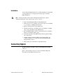
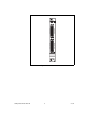
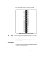
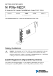
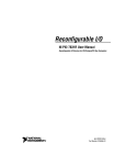
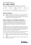
Getting Started with the
NI PXI-7811R
This document explains how to set up the National Instruments PXI-7811R
device.
Introduction
The PXI-7811R is an R Series reconfigurable I/O (RIO) device with
160 digital I/O (DIO) lines.
Traditional digital I/O devices have a fixed functionality provided by an
application-specific integrated circuit (ASIC), but the PXI-7811R has a
field-programmable gate array (FPGA) that allows you to define device
functionality and timing.
You can use the LabVIEW FPGA Module to graphically design the
PXI-7811R timing and functionality without having to learn a low-level
programming language or a hardware description language (HDL)
traditionally used for FPGA design. With the LabVIEW FPGA Module,
you create or download a custom virtual instrument (VI) to the FPGA.
You can reconfigure the PXI-7811R device with a new VI at any time.
You can use the LabVIEW Real-Time Module to communicate and control
the PXI-7811R device while performing additional tasks, such as real-time
floating-point processing and data logging.
Note If you are using LabVIEW but not the LabVIEW FPGA Module, you can create VIs
that run in LabVIEW to control existing FPGA VIs, but you cannot create new FPGA VIs.
The PXI-7811R device has Flash memory that you can use to store VIs.
You can configure VIs to load to the FPGA and to run when the device
powers up.
Required Items
This section provides lists of the items necessary for getting started using
the PXI-7811R with Windows 2000/XP and the LabVIEW Real-Time
Module.
Documentation
The NI PXI-7811R User Manual describes the electrical and mechanical
aspects of the PXI-7811R device and contains information about device
operation and programming. This document is included on the NI-RIO CD
and is also available at ni.com/manuals.
LabVIEW Help is available in LabVIEW by selecting Help»VI, Function,
& How-To Help.
Windows 2000/XP
Use the following items to set up and use the PXI-7811R with
Windows 2000/XP.
❑ PXI-7811R device
❑ The following software packages:
–
LabVIEW 7.1 or later
–
LabVIEW FPGA Module 1.1 or later—required to develop
custom FPGA VIs for the PXI-7811R device
–
NI-RIO 1.1 or later—included with the PXI-7811R
❑ PXI/CompactPCI chassis and a PXI/CompactPCI embedded
controller running Windows 2000/XP (or any computer running
Windows 2000/XP and a MXI-3 link to a PXI/CompactPCI chassis)
❑ At least one cable and device for connecting signals to the PXI-7811R
LabVIEW Real-Time Module for ETS
Use the following items to set up and use the PXI-7811R with the
LabVIEW FPGA Module and the LabVIEW Real-Time Module.
❑ PXI-7811R device
❑ The following software packages:
Getting Started with the NI 7811R
–
LabVIEW 7.1 or later
–
LabVIEW Real-Time Module for ETS 7.1 or later
2
ni.com
–
LabVIEW FPGA Module 1.1 or later—required to develop
custom FPGA VIs for the PXI-7811R device
–
NI-RIO 1.1 or later—included with the PXI-7811R
❑ PXI/CompactPCI chassis and real-time PXI controller
❑ One of the following host computers, depending upon your
application, running Windows 2000/XP:
–
PC
–
Laptop computer
–
PXI/CompactPCI embedded controller
❑ At least one cable and device for connecting signals to the PXI-7811R
❑ CAT 5 Ethernet crossover cable if the real-time PXI system is not
configured on a network. To connect the PXI system to a network port,
use a standard CAT 5 10/100Base-T Ethernet cable.
Installing Software
The following instructions describe how to install the NI-RIO device
drivers and LabVIEW.
Installing LabVIEW, the LabVIEW Real-Time Module for ETS, and the
LabVIEW FPGA Module
Use the following sequence when installing LabVIEW, the LabVIEW
Real-Time Module for ETS, and the LabVIEW FPGA Module. For more
detailed information about software requirements, refer to the LabVIEW
FPGA Release Notes.
If you are using NI-RIO without LabVIEW, skip these steps and complete
the steps in the Installing NI-RIO Device Drivers section.
You must install LabVIEW 7.0 or later and the LabVIEW modules you will be using
with the NI 7811R before installing the NI-RIO device drivers. For LabVIEW installation
instructions, refer to the LabVIEW Release Notes.
Note
1.
Install LabVIEW for Windows from the LabVIEW CD.
2.
Install the LabVIEW Real-Time Module for ETS from the LabVIEW
Real-Time CD.
3.
Install LabVIEW FPGA from the LabVIEW FPGA CD.
4.
Install the NI-RIO device drivers. Refer to the Installing NI-RIO
Device Drivers section for driver installation instructions.
© National Instruments Corporation
3
Getting Started with the NI 7811R
Installing NI-RIO Device Drivers
Complete the following steps to install the NI-RIO device drivers that are
included with the PXI-7811R device. If you are using LabVIEW, complete
the installation instructions in the Installing LabVIEW, the LabVIEW
Real-Time Module for ETS, and the LabVIEW FPGA Module section
before installing the NI-RIO device drivers.
1.
Run setup.exe from the NI-RIO CD and follow the setup
instructions.
2.
Follow the onscreen instructions until the Feature Tree window
appears.
3.
In the Feature Tree window, select the components to install. You must
install NI-VISA, NI-RIO, and NI Measurement & Automation
Explorer (MAX).
4.
Follow the onscreen instructions to complete the driver installation.
5.
Reboot your computer.
Installing Hardware
This section describes how to unpack and install the PXI-7811R device.
You can install the PXI-7811R in any available peripheral slot in the PXI
or CompactPCI chassis.
Note
You must install the NI-RIO device drivers before installing the PXI-7811R device.
Unpacking
The PXI-7811R device ships in an antistatic package to prevent
electrostatic discharge from damaging device components. To prevent such
damage when handling the device, take the following precautions:
Caution
•
Ground yourself using a grounding strap or by holding a grounded
object, such as your computer chassis.
•
Touch the antistatic package to a metal part of the computer chassis
before removing the devices from the package.
Never touch the exposed pins of connectors.
Remove the devices from the package and inspect the devices for loose
components or any other sign of damage. Notify NI if the devices appear
damaged in any way. Do not install damaged devices into the computer.
Store the PXI-7811R in the antistatic envelope when not in use.
Getting Started with the NI 7811R
4
ni.com
Installation
You can install the PXI-7811R in any available peripheral slot in the PXI
or CompactPCI chassis. Complete the following steps to install the
PXI-7811R device.
You must install the software before installing the hardware. For software
installation instructions, refer to the Installing Software section.
Note
1.
Power off and unplug the PXI or CompactPCI chassis.
2.
Make sure there are no lit LEDs on the chassis. Wait for any lit LEDs
to go out before continuing the installation.
3.
Remove the filler panel for the peripheral slot.
4.
Ground yourself using a grounding strap or by touching a grounded
object, such as the PXI or CompactPCI chassis.
5.
Insert the PXI-7811R into the slot. Use the injector/ejector handle to
fully inject the PXI-7811R into place.
6.
Screw the front panel of the PXI-7811R to the front panel mounting
rails of the chassis.
7.
Visually verify the installation. Make sure the PXI-7811R is not
touching other devices or components and that the PXI-7811R is
fully inserted into the slot.
8.
Plug in and power on the PXI or CompactPCI chassis.
Connecting Signals
The PXI-7811R has four DIO connectors with 40 DIO lines per DIO
connector.
Figure 1 shows the I/O connector locations for the PXI-7811R. The
I/O connectors are numbered starting at zero.
© National Instruments Corporation
5
Getting Started with the NI 7811R
NI PXI-7811R
Reconfigurable I/O
CONNECTOR 0 (DIO)
CONNECTOR 3 (DIO)
CONNECTOR 1 (DIO)
CONNECTOR 2 (DIO)
Figure 1. PXI-7811R Connector Locations
Getting Started with the NI 7811R
6
ni.com
Figure 2 shows the pin assignments for all I/O connectors on the
PXI-7811R.
DIO38
DIO36
34 68
DIO34
33 67
32 66
DIO32
31 65
DIO30
DIO28
30 64
29 63
+5V
28 62
+5V
27 61
26 60
DGND
DGND
DGND
DGND
25 59
24 58
23 57
DIO39
DIO37
DIO35
DIO33
DIO31
DIO29
DIO27
DIO26
DIO25
DIO24
DIO23
DIO22
DGND
DGND
DGND
22 56
DGND
DGND
DGND
19 53
18 52
17 51
DIO18
DIO17
DGND
DGND
16 50
15 49
14 48
DIO15
DIO14
DGND
DGND
DGND
DGND
DGND
DGND
DGND
DGND
DGND
DGND
DGND
DGND
DGND
DGND
21 55
20 54
13 47
12 46
11 45
10 44
9 43
8 42
DIO21
DIO20
DIO19
DIO16
DIO13
DIO12
DIO11
DIO10
DIO9
DIO8
7
6
5
41
40
39
DIO7
DIO6
DIO5
DIO4
4
3
2
38
37
36
DIO3
DIO2
DIO1
1
35
DIO0
Figure 2. PXI-7811R I/O Connector Pin Assignments
Caution Connections that exceed any of the maximum ratings of input or output signals
on the PXI-7811R can damage the PXI-7811R and the computer. NI is not liable for any
damage resulting from such signal connections. Refer to the PXI-7811R User Manual for
the maximum input ratings for each signal.
For detailed information about connecting I/O signals, refer to the
NI 7811R User Manual.
Cabling Options
Accessing the signals on the I/O connectors requires at least one cable and
one signal accessory. Table 1 summarizes the National Instruments cables
available for use with the NI 7811R device.
© National Instruments Corporation
7
Getting Started with the NI 7811R
Table 1. Cabling Options
Cable
Description
SH68-C68-S
For connecting signals from the DIO connector to the NI SCB-68 terminal
block.
NSC68-5050
For direct connection of the NI 7811R and SSR backplanes.
Routes signals to connectors that attach directly to SSR backplanes.
Documentation Resources
Refer to the following documentation for information about the
LabVIEW FPGA Module, R Series hardware, and VIs necessary for your
application.
•
LabVIEW FPGA Module Release Notes—describes the software
installation and other known software issues
•
LabVIEW FPGA Module User Manual—describes the LabVIEW
FPGA Module software and techniques for building applications in
LabVIEW with the LabVIEW FPGA Module
•
PXI-7811R User Manual—describes the electrical and mechanical
aspects of the PXI-7811R device and contains information concerning
its operation and programming
•
LabVIEW Help—describes the VIs and function reference information
•
CompactRIO R Series Expansion System Installation
Instructions—describes how to install the CompactRIO R Series
Expansion chassis and CompactRIO I/O modules
Where to Go from Here
Refer to the LabVIEW FPGA Module Release Notes for information about
getting started with LabVIEW FPGA VIs and host VIs. This document also
provides examples for verifying that your software and hardware are
properly installed. To access this document, select Start»Programs»
National Instruments»LabVIEW»Module Documents.
CompactRIO™, LabVIEW™, MXI™, National Instruments™, NI™, ni.com™, and NI-VISA™ are
trademarks of National Instruments Corporation. Product and company names mentioned herein are
trademarks or trade names of their respective companies. For patents covering National Instruments
products, refer to the appropriate location: Help»Patents in your software, the patents.txt file on
your CD, or ni.com/patents.
© 2004 National Instruments Corp. All rights reserved.
*323792A-01*
323792A-01
Apr04