1
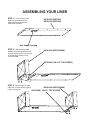
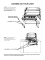
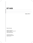
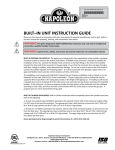
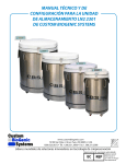
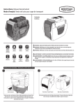
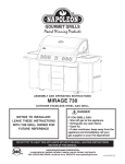
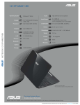
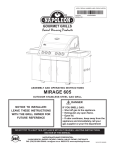
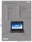
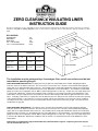
ZERO CLEARANCE INSULATING LINER
INSTRUCTION GUIDE
This liner is designed for use in a combustible enclosure; the liner must be supported from the bottom by a ledge on either side or a full deck
beneath the liner (refer to opening diagram). Please use this manual in conjunction with your main manual to properly assemble your built
in grill.
KIT CONTENTS
BOTTOM PANEL
SIDE PANELS
REAR PANEL
#8 x ½” TEK SCREWS
#14 x ½” HEX HEAD SCREWS
1PC
2PCS
1PC
15PCS
6PCS
W
2”MIN
6.500”
2.000”
H
D
Model
Dimensions
W
D
H
BIZC450
35.875”
22.937”
11.125”
BIZC600
44.125”
22.937”
11.125”
GAS
INLET
OPENING
34” RECOMMENDED
The installation must be performed by a licensed gas fitter, and all connections must be leak
tested before operating the grill.
BUILT IN PROPANE GAS HOOK-UP: The piping up to the gas grill is the responsibility of the installer and piping should be
located as shown in the built-in instructions. Do not use hose to connect the unit. It must be connected with either rigid pipe,
copper tube or an approved flexible metal connector. The installation must comply with CAN B149.1 Natural Gas and Propane
installation code in Canada, or to the National Fuel Gas code, ANSI Z223.1 in the United States. The minimum recommended
piping size is NPS 1/2" for rigid pipe, and 1/2" OD for copper tubing (based on a 20 ft run). Longer runs may require larger sizes
to conform with CAN B149.1. Propane Gas Installation Code in Canada or to the National Fuel Gas Code, ANSI Z223.1 in the
United States. The gas supply must be connected to the 3/8” flare elbow fitting located under the right hand side of the control
panel. If installing a side burner, a separate line must be branched off to the side burner unit and enter the side burner opening
at the specified location. If the enclosure is to house a propane cylinder, the tank portion of the enclosure must be ventilated
according to local codes, and must not have communication with the cavity used to enclose the gas grill. The tank can not be
stored below the gas grill.
BUILT IN NATURAL GAS HOOK-UP: The piping up to the gas grill is the responsibility of the installer and piping should be
located as shown in the built-in instructions. Do not use hose to connect the unit. It must be connected with either rigid pipe,
copper tube or an approved flexible metal connector. The installation must comply with CAN B149.1 Natural Gas and Propane
Installation Code in Canada, or to the National Fuel Gas Code, ANSI Z223.1 in the United States. The minimum recommended
piping size is NPS 1/2" for rigid pipe, and 5/8" OD for copper tubing (based on a 20 ft run). Longer runs may require larger sizes
to conform with CAN B149.1. Natural Gas Installation Code in Canada or to the National Fuel Gas Code, ANSI Z223.1 in the
United States.
Built in units are supplied with a drip pan which holds only a minimal amount of grease. To prevent grease fires, the pan
must be cleaned after each use.
N415-0152 NOV21/06
ASSEMBLING YOUR LINER
STEP 1: Place stainless steel
bottom panel on table with gas
supply opening to the front left
hand corner as shown.
N010-0492 (BIZC450)
N010-0493 (BIZC600)
Gas Supply Opening
STEP 2: Slide side panel onto
bottom panel ensuring holes on face
of panel are facing you. Line up holes
and fasten with (4) #8 x 1/2” tek
screws provided.
N010-0496 (BIZC450/600)
N570-0008 ( #8 x1/2” TEK SCREW)
STEP 3: Repeat step 2 for other
side panel. Ensure holes on face of
panel are facing you.
N010-0496 (BIZC450/600)
N570-0008 ( #8 x1/2” TEK SCREW)
ASSEMBLING YOUR LINER
STEP 4: Attach rear panel to
enclosure, fastening with (7) #8 x 1/2”
tek screws.
N010-0494 (BIZC450)
N010-0495 (BIZC600)
N570-0008 ( #8 x1/2” TEK SCREW)
Your liner is now ready to be mounted into your enclosure.
ASSEMBLING YOUR LINER
STEP 6: Attach mounting brackets
to the bottom of your grill using (4)
#14 x 1/2” hex head screws. Line up
holes in brackets with holes on either
edge of underside of base.
N080-0198P (BIZC450)
N080-0199P (BIZC600)
N570-0026 #14 x 1/2” SCREW
STEP 7: Lower gas grill into liner.
Fasten to bottom panel of liner
through front holes in brackets using
#14 x 1/2” screws.
N570-0026 #14 x 1/2” SCREW
The entire installation must be leak tested prior to operating your grill (refer to leak test
section of your manual for detailed instructions).