1
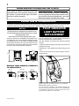
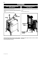
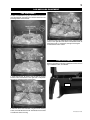
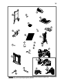
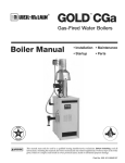
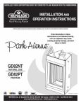
1
W415-0559 / 02.07.06
W415-0559 / 02.15.06
2
WARNINGS & SAFETY PRECAUTIONS
Do not store gasoline or other
flammable vapours and liquids in the
vicinity of this or any other appliance.
1.
2.
3.
Installation and service must be
performed by a qualified installer,
service agency or the gas supplier.
Follow the installation directions.
4.
5.
6.
WHAT TO DO IF YOU SMELL GAS
Do not try to light any appliance.
Do not use any phone in your building.
Immediately call your gas supplier
from a neighbor's phone. Follow the
gas supplier's instructions.
Do not touch any electrical switch.
If you cannot reach your gas supplier,
call the fire department.
If this fireplace is not properly
installed, a house fire may result.
W415-0559 / 02.15.06
3
TABLE of CONTENTS
2.
4.
5.
6.
7.
8.
9.
Warnings and Safety Precautions
What to do if you smell gas
Warranty
General Instructions
General Information
Mobile Home Installation
Location and Clearances
Pilot Indicator Light - Battery Install
Blower Installation
Gas Installation
Finishing
Screen Installation and Removal
Cast Front Installation and removal
Log Placement
Logo Placement
10. Operation
Operating Instructions
For Your Safety Read Before Lighting
Lighting Instructions
To Turn Off Gas
11. Adjustments
Venturi Adjustment
Orifice Replacement
Oxygen Depletion Sensor Pilot Cleaning
Maintenance
12. Replacements
Replacement Parts
Accessories
14. Trouble Shooting
16. Service History
PLEASE RETAIN THIS MANUAL FOR FUTURE REFERENCE
WARNING
• Under no circumstances should this heater be modified.
• Provide adequate ventilation and combustion air. Provide adequate accessibility clearance for
servicing and operating the heater. Never obstruct the front opening of the heater.
• If heater shuts off, do not re-light until you provide fresh air. If heater keeps shutting off, have it
serviced. Keep burner and control compartment clean.
• Do not burn wood or other materials in this heater.
• Adults and especially children should be alerted to the hazards of high surface temperatures
and should stay away to avoid burns or clothing ignition. Keep young children and animals away
when the stove is hot.
• Due to high temperatures, the heater should be located out of traffic and away from furniture
and draperies.
• Clothing or other flammable material should not be placed on or near the heater.
• Any safety screen or guard removed for servicing must be replaced prior to operating the heater.
• It is imperative that the control compartments, burners and circulating air passageways in the
heater are kept clean. The heater should be inspected before use and at least annually by a
qualified service person. More frequent cleaning may be required due to excessive lint from
carpeting, bedding material, etc. The heater area must be kept clear and free from combustible
materials, gasoline and other flammable vapours and liquids.
• Furniture or other objects must be kept a minimum of 4 feet away from the front of the fireplace.
• Do not use this heater if any part has been under water. Immediately call a qualified service
technician to inspect the heater and to replace any part of the control system and any gas
control which has been under water.
NOTE: changes, other than editorial, are denoted by a vertical line in the margin.
W415-0559 / 02.15.06
4
NAPOLEON products are manufactured under the strict Standard of the world recognized
ISO 9001 : 2000 Quality Assurance Certificate.
NAPOLEON products are designed with superior components and materials, assembled by trained craftsmen who take great
pride in their work. The burner and valve assembly are leak and test-fired at a quality test station. The complete fireplace is
test-fired and thoroughly inspected by a qualified technician before packaging to ensure that you, the customer, receives the
quality product that you expect from NAPOLEON.
NAPOLEON GAS FIREPLACE PRESIDENT'S LIFETIME LIMITED WARRANTY
The following materials and workmanship in your new NAPOLEON gas fireplace are warranted against
defects for as long as you own the fireplace. This covers: combustion chamber, heat exchanger, stainless steel
burner, phazer™ logs and embers, gold plated parts against tarnishing, porcelainized enamelled components
and aluminium extrusion trims.
Electrical (110V and millivolt) components and wearable parts such as catalytic tiles, blowers, gas valves, thermal
switch, switches, wiring, remote controls, ignitor, gasketing, and pilot assembly are covered and NAPOLEON
will provide replacement parts free of charge during the first year of the limited warranty.
Labour related to warranty repair is covered free of charge during the first year. Repair work, however, requires
the prior approval of an authorized company official. Labour costs to the account of napoleon are based on a predetermined rate schedule and any repair work must be done through an authorized napoleon dealer.
CONDITIONS AND LIMITATIONS
NAPOLEON warrants its products against manufacturing defects to the original purchaser only -- i.e., the individual or legal entity (registered customer) whose name appears on the warranty registration card filed with NAPOLEON -- provided that the purchase was made
through an authorized NAPOLEON dealer and is subject to the following conditions and limitations:
This factory warranty is nontransferable and may not be extended whatsoever by any of our representatives.
The gas fireplace must be installed by a licenced, authorized service technician or contractor. Installation must be done in accordance
with the installation instructions included with the product and all local and national building and fire codes.
This limited warranty does not cover damages caused by misuse, lack of maintenance, accident, alterations, abuse or neglect and parts
installed from other manufacturers will nullify this warranty.
This limited warranty further does not cover any scratches, dents, corrosion or discolouring caused by excessive heat, abrasive and
chemical cleaners nor chipping on porcelain enamel parts, mechanical breakage of PHAZER™ logs and embers, nor any venting components used in the installation of the fireplace.
NAPOLEON warrants its stainless steel burners against defects in workmanship and material for life, subject to the following conditions: During the first 10 years NAPOLEON will replace or repair the defective parts at our option free of charge. From 10 years to life,
NAPOLEON will provide replacement burners at 50% of the current retail price.
In the first year only, this warranty extends to the repair or replacement of warranted parts which are defective in material or workmanship
provided that the product has been operated in accordance with the operation instructions and under normal conditions.
After the first year, with respect to this President's Limited Lifetime Warranty, NAPOLEON may, at its discretion, fully discharge all obligations
with respect to this warranty by refunding to the original warranted purchaser the wholesale price of any warranted but defective part(s).
After the first year, NAPOLEON will not be responsible for installation, labour or any other costs or expenses related to the reinstallation
of a warranted part, and such expenses are not covered by this warranty.
Notwithstanding any provisions contained in this President's Limited Lifetime Warranty, NAPOLEON’S responsibility under this warranty
is defined as above and it shall not in any event extend to any incidental, consequential or indirect damages.
This warranty defines the obligations and liability of NAPOLEON with respect to the NAPOLEON gas fireplace and any other warranties
expressed or implied with respect to this product, its components or accessories are excluded.
NAPOLEON neither assumes, nor authorizes any third party to assume, on its behalf, any other liabilities with respect to the sale of this
product. NAPOLEON will not be responsible for: over-firing, downdrafts, spillage caused by environmental conditions such as rooftops,
buildings, nearby trees, hills, mountains, inadequate vents or ventilation, excessive venting configurations, insufficient makeup air, or
negative air pressures which may or may not be caused by mechanical systems such as exhaust fans, furnaces, clothes dryers, etc.
Any damages to fireplace, combustion chamber, heat exchanger, brass trim or other component due to water, weather damage, long
periods of dampness, condensation, damaging chemicals or cleaners will not be the responsibility of NAPOLEON.
The bill of sale or copy will be required together with a serial number and a model number when making any warranty claims from your
authorized dealer. The warranty registration card must be returned within fourteen days to register the warranty.
ALL SPECIFICATIONS AND DESIGNS ARE SUBJECT TO CHANGE WITHOUT PRIOR NOTICE DUE TO ON-GOING PRODUCT IMPROVEMENTS. NAPOLEON® IS A REGISTERED
TRADEMARK OF WOLF STEEL LTD. PATENTS U.S. 5.303.693.801 - CAN. 2.073.411, 2.082.915. © WOLF STEEL LTD.
W415-0559 / 02.15.06
5
GENERAL INSTRUCTIONS
GENERAL INFORMATION
ANY CHANGE TO THIS HEATER OR ITS CONTROLS CAN BE DANGEROUS AND IS PROHIBITED.
FOR YOUR SATISFACTION, THIS FIREPLACE HAS BEEN
TEST-FIRED TO ASSURE ITS OPERATION AND QUALITY!
Maximum input is 23,000 BTU/hr for natural gas and propane.
When the fireplace is installed at elevations above 2,000ft,
and in the absence of specific recommendations from the
local authority having jurisdiction, the certified high altitude
input rating shall be reduced at the rate of 4% for each additional 1,000ft.
THIS GAS FIREPLACE SHOULD BE INSTALLED AND
SERVICED BY A QUALIFIED INSTALLER to conform with
local codes. Installation practices vary from region to region
and it is important to know the specifics that apply to your
area, for example: in Massachusetts State:
•
The appliance off valve must be a “T” handle gas cock.
• The flexible connector must not be longer than 36 inches.
• The appliance is not approved for installation in a bedroom or
bathroom unless the unit is a direct vent sealed combustion
product.
• WARNING: This product must be installed by a licensed
plumber or gas fitter when installed within the commonwealth
of Massachusetts.
• Un-vented room heater shall be installed in accordance with
527 CMR 30.00 and 248 CMR 3.00 through 7.00.
• Sellers of un-vented propane or natural gas-fired
space/room heaters shall provide to each purchaser a copy
of 527 CMR 30.00 upon the sale of the unit from
http://www.napoleonfireplaces.com/Webshare/installation_
manuals/mass_requirements.pdf
In absence of local codes, install the GVFS20 to the current
National Fuel Gas Code, ANSI Z223.1 Installation Code which
can be obtained from:
American Nation Standards Institute Inc.
1430 Broadway
New York, NY 10018
or
National Fire Protection Association Inc.
Batterymarch Park
Quincy, MA 02269
The fireplace and its individual shutoff valve must be disconnected from the gas supply piping system during any pressure
testing of that system at test pressures in excess of ½ psig
(3.5 kPa). The fireplace must be isolated from the gas supply
piping system by closing its individual manual shutoff valve
during any pressure testing of the gas supply piping system
at test pressures equal to or less than ½ psig (3.5 kPa).
The stove, when installed with a blower, must be electrically
connected and grounded in accordance with local codes. In
the absence of local codes, use the current ANSI/NFPA 70
NATIONAL ELECTRICAL CODE. The blower power cord
must be connected into a properly grounded receptacle. The
grounding prong must not be removed from the cord plug.
This heater must not be installed in a bedroom or bathroom.
This fireplace is only for use with the type of gas indicated on the rating plate. This fireplace is not convertible
for use with other gases, unless a certified kit is used.
Minimum inlet gas supply pressure is 4.5 inches water column for natural gas and 11 inches water column for propane.
Maximum inlet gas pressure is 7 inches water column for
natural gas and 13 inches water column for propane. Manifold
pressure under flow conditions is 3.5 inches water column for
natural gas and 10 inches water column for propane.
No external electricity (110 volts or 24 volts) is required
for the gas system operation. Expansion / contraction
noises during heating up and cooling down cycles are normal
and are to be expected.
This heater is equipped with a pilot light
safety system referred to as an OXYGEN
DEPLETION SENSOR and is designed to
turn off the heater if not enough fresh air is
available.
Use only accessories designed for and listed
with your specific fireplace.
MOBILE HOME INSTALLATION
Suitable for mobile home installation where the
mobile home has been permanently placed on its
site.
This fireplace may be installed in an aftermarket
permanently located, manufactured (mobile)
home, where not prohibited by local codes.
For mobile home installations, the fireplace must be
fastened in place. It is recommended that the fireplace be secured in all installations. Use the levelling
/ securing kit, GDSLL-KT, for this purpose.
W415-0559 / 02.15.06
6
CARBON MONOXIDE POISONING MAY LEAD TO DEATH
Early signs of carbon monoxide poisoning
resemble the flu, with headache, dizziness and/
or nausea. If you have these signs, the heater
may not be working properly.
Get fresh air at once! Have heater serviced.
Some people---pregnant women, persons with
heart or lung disease, anemia, those under the influence of alcohol, those at high altitudes--- are more
affected by carbon monoxide than others.
LOCATION & CLEARANCES
THIS GAS STOVE SHOULD BE INSTALLED AND SERVICED BY A QUALIFIED INSTALLER to conform with local codes.
Installation practices vary from region to region and it is important to know the specifics that apply to your area,
GVFS20
Provide adequate ventilation and combustion air.
Provide adequate accessibility clearance for servicing
and operating the stove.
Never obstruct the front opening of the stove.
As long as clearance to combustibles is kept within the required distances, the most desirable and beneficial location
for a Napoleon stove is in the centre of a building, thereby
allowing the most efficient use of the heat created. The location of windows, doors and the traffic flow in the room where
the stove is to be located should be considered.
PILOT INDICATOR
LIGHT BATTERY
REPLACEMENT
If the pilot indicator light no longer flashes and the pilot is
burning, the batteries may require replacing.
Four "AA" batteries are required and should be replaced
annually.
1. Open the switch housing by removing the top screw, then
pivoting the box open.
2. Remove the 4 "AA" batteries and replace using the new
ones.
19 1/4"
9 5/8"
25 / "
38
3. Pivot the box closed and re-secure using the screw removed in step 1.
15 3/4"
MAINTAIN THESE MINIMUM CLEARANCES
TO COMBUSTIBLES:
A. 4"
B. 2"*
C. 2"
+
+ -
-
+
+
-
FIGURE 2
STOVE SHOULD NOT BE INSTALLED DIRECTLY ON CARPETING.
MINIMUM 48". FROM TOP TO CEILING
*IF LESS THAN 5" CLEARANCE IS MAINTAINED BETWEEN THE
BACK OF THE STOVE AND THE BACK WALL, IT WILL BE NECESSARY
TO DISCONNECT THE GAS PIPE TO MOVE THE STOVE OUT FOR
INSTALLATION OR SERVICE OF THE BLOWER.
W415-0559 / 02.15.06
7
BLOWER INSTALLATION
Blower (SEE LOCATION AND CLEARANCES IN INSTRUCTION MANUAL)
1. Cut and remove the tie securing the blower switch wires
to the heat shield.
2. Connect the white wire coming from below the unit to the
terminal on the blower.
3. Connect the black blower wire to the black wire coming
from below the unit.
4. Insert the clips on the blower housing into the cutouts in the
rear shield. Push down to lock the clips into position.
5. Secure the blower using the screw and lock washer supplied.
Note: Ensure that all the wires are tucked into the blower
switch housing.
7
7
9
Switches
6. Open the switch housing by removing the top screw.
7. With the 2 screws THERMODISC
and extension bracket BRACKET
supplied in the unit
baggie, fasten extension
bracket to the thermodisc
bracket. Install bracket
assembly as shown, using
2 of the screws supplied.
THERMODISC
Connect the flagged leads
EXTENSION
to the terminals of the
BRACKET
thermodisc.
8. Remove the knock out from the switch housing label. Install
the variable speed switch (rheostat) into the housing with the
wires facing up. Secure the switch to the housing using the
pal nut and the knob supplied.
9. Connect the male connector on the switch to the female
connector coming from the unit.
10. Pilot Indicator Light: Install the batteries as shown.
Replace the batteries annually. Note: If replacing the pilot
indicator light , ensure that the red wire lead connects to
the red lead of the thermopile and black to white.
11. Tuck all of the wires into the switch housing and close.
Secure using the screw removed in step 6.
7
8
1
7
9
4
4
2
This unit comes equipped
with a pilot indicator light 3
that blinks every few
seconds when the pilot
is on.
8
5
For more information see
step #10.
GAS INSTALLATION
1. Install rigid black pipe, or 1/2" type L copper tubing with a
shut-off valve to the stove.
2. Seal and tighten the gas line securely to a flex connector.
DO NOT KINK FLEXIBLE CONNECTOR.
3/8NPT
FLEXIBLE
CONNECTOR
ADAPTER
FITTING
1/2FPT
1
TP
LO
FF
ON
O
TH
PLT
IH
OI
PILOT
3
BLACK
PIPE
TP TH
2
SHUT OFF
VALVE
3. Check for gas leaks by
brushing on a soap and
water solution. Do not use
open flame.
For ease of accessibility, an optional remote wall switch or
millivolt thermostat may be installed in a convenient location. Route 2 strand solid core millivolt wire from the gas
stove to the wall switch / millivolt thermostat. The recommended maximum lead length depends on the wire size:
wire size max. length
14gauge
100 feet
16gauge
60 feet
18gauge
40 feet
Disconnect the existing wires from terminals 1 and 3 (from
the on/off switch) and replace with the leads from the wall
switch/millivolt thermostat.
W415-0559 / 02.15.06
8
FINISHING
CAST FRONT INSTALLATION
AND REMOVAL
SCREEN INSTALLATION
AND REMOVAL
1. Lift the top cast piece off of the unit.
2. Detach the front cast piece from the side pieces by remov- 1. Unscrew the four screws (one in each corner) from the
ing the screws from the brackets located in the upper inside screen.
2. Remove screen from unit
corners.
3. Slide the front straight up to remove.
3
2
SCREWS
BRACKET
FRONT
FRONT
TAB
Four
Screws
FRONT
LEGS
Follow the above steps in reverse in order to reinstall
the cast front. Ensure that the tabs on the underside of
the front fit behind the front legs.
W415-0559 / 02.15.06
Follow the above steps in reverse in order to reinstall
the screen.
9
LOG AND LOGO PLACEMENT
LOG PLACEMENT
In order to assemble the log set, the screen and cast front
must be removed, see Cast Front / Screen Removal in the
Finishing section of this manual.
3. Place the hole in the underside of log #3 onto the locating
screw, on the right side of the burner. The bottom branch of
log #3 sits infront of, and against, the right end of log #2.
4. Reinstall the screen & front.
LOGO PLACEMENT
Remove the backing of the logo supplied and centre over the
logo installation holes, as indicated.
1. Place the rear log, as shown, onto the rear log support
brackets. Bend the bracket on the right side to help retain
the rear log against the back of the firebox.
LOGO
2. Place the hole in the underside of log #2 onto the locating
screw, on the left side of the burner. The fibre burner is formed
to cradle the centre of the log.
W415-0559 / 02.15.06
10
OPERATION
OPERATING INSTRUCTIONS
If heater shuts off, do not relight until you provide fresh air. If heater keeps shutting off, have it
serviced. Keep burner and control compartment
clean.
When lit for the first time, the fireplace will emit a slight odour
for a few hours. This is a normal temporary condition caused
by the curing of the logs and the “burn-in” of internal paints
and lubricants used in the manufacturing process and will not
occur again. After extended periods of non-operation such as
following a vacation or a warm weather season, the fireplace
may emit a slight odour for a few hours. This is caused by
dust particles burning off. In both cases, open a window to
sufficiently ventilate the room.
FOR YOUR SAFETY READ BEFORE LIGHTING:
WARNING: IF YOU DO NOT FOLLOW THESE INSTRUCTIONS EXACTLY, A FIRE OR EXPLOSION
MAY RESULT CAUSING PROPERTY DAMAGE, PERSONAL INJURY OR LOSS OF LIFE.
When lighting and re-lighting, the gas knob cannot be turned
from pilot to off unless the knob is depressed.
ON
O FF
C. Use only your hand to push in and turn the gas control
knob. Never use tools. If the knob will not push in and
turn by hand, do not try to repair it. Call a qualified service
technician. Force or attempted repair may result in a fire
or explosion.
D. Do not use this fireplace if any part has been under water.
Immediately call a qualified service technician to inspect
the fireplace and replace any part of the control system
and any gas control which has been under water.
• Do not try to light any appliance.
WHAT TO DO IF YOU SMELL GAS:
• Do not touch any electric switch; do not use any phone
in your building.
• Immediately call your gas supplier from a neighbour’s
phone. Follow the gas supplier’s instructions.
• If you cannot reach your gas supplier, call the fire department.
PILOT
A. This fireplace is equipped with a pilot which must be lit
by hand while following these instructions exactly.
B. Before operating smell all around the fireplace area for
gas and next to the floor because some gas is heavier
than air and will settle on the floor.
OXYGEN DEPLETION SENSOR
GAS KNOB
LIGHTING INSTRUCTIONS
burner may be delayed from 1-2 minutes.
When the pilot has been left burning, ignition of the main
burner should occur almost immediatley.
10. If equipped with remote on-off switch, main burner may
not come on when you turn the valve to on. Remote switch
must be in the on position to ignite burner.
11. Turn on all electric power to the fireplace.
TP TH
GAS KNOB AT OFF
TP
LO
FF
ON
O
TH
PLT
IH
OI
PILOT
1. STOP! Read the above safety information on this label.
2. Set the thermostat to lowest setting.
3. Turn off all electric power to the fireplace.
4. Open the control door. Turn the gas knob clockwise
to off.
5. Wait five (5) minutes to clear out any gas. If you smell gas
including near the floor, STOP! Follow “B” in the above
safety information on this label. If you don’t smell gas go
to the next step.
6. Find pilot located in front of the back log.
7. Turn gas knob counter-clockwise
to pilot.
8. Depress and hold gas knob while lighting the pilot with
the push button ignitor. Keep knob fully depressed for one
minute, then release. If pilot does not continue to burn
repeat steps 3 through 7.
9. With pilot lit, turn gas knob counter-clockwise
to on.
When the pilot has been turned off, ignition of the main
TO TURN OFF GAS
1. Turn off all electric power to the fireplace if service is to
be performed.
W415-0559 / 02.15.06
2. Push in gas control knob slightly and turn clockwise
to off. Do not force.
11
ADJUSTMENTS
MAINTENANCE
TURN OFF THE GAS AND UNPLUG ELEC- opening and the area surrounding the logs clean by vacuumTRICAL POWER BEFORE SERVICING THE ing or brushing, at least once a year.
3. Check to see that all burner ports are burning. Clean out
STOVE!
any of the ports which may not be burning or are not burning
CAUTION: Label all wires prior to disconnection when servicing controls. Wiring errors can cause improper and dangerous
operation. Verify proper operation after servicing. This stove
should be inspected before use and at least annually by a
qualified service person. The fireplace area must be kept
clear and free of combustible materials, gasoline or other
flammable vapours and liquids.
1. In order to properly clean the burner and pilot assembly,
remove the logs exposing both assemblies.
2. Keep the control compartment, logs, burner, air shutter
VENTURI ADJUSTMENT
1. In order to properly clean the burner and pilot assembly,
remove the logs exposing both assemblies.
2. Keep the control compartment, logs, burner, air shutter
opening and the area surrounding the logs clean by vacuuming or brushing, at least once a year.
Air shutter adjustment must only be done by a
qualified gas installer!
Closing the air shutter will cause a more yellow flame,
but can lead to carboning. The flame may not appear
yellow immediately; allow 15 to 30 minutes for the final
flame colour to be established.
properly. Take care not to enlarge these parts.
4. Check to see that the pilot flames are large enough to
engulf the thermocouple and the thermopile on one leg and
reaches toward the burner on the other leg.
5. Replace the cleaned logs.
6. Check to see that the main burner ignites completely on
all openings when the gas knob for the burner is turned on.
A 5-10 second total light-up period is satisfactory. If ignition
takes longer, consult your Napoleon dealer/distributor.
ORIFICE REPLACEMENT
1. Remove the cast front and the
screen, see Cast Front and Screen
Removal in the FINISHING section
of this manual.
2. Remove the 2 securing screws
indicated and remove the burner
assembly.
3. The orifice is located on the left
ORIFICE
LOCATION
hand side.
4. Reinstall the burner ensuring that
BURNER
ASSEMBLY
the venturi tube fits over the orifice
SCREW
and replace the screws.
LOCATIONS
Care should be taken not to damage
the gas pipe. When removing and replacing the orifice, using
a 9/16" socket wrench, a 7/8" back-up wrench must be used
on the manifold, located below the housing, to ensure that
the aluminium tubing does not twist or kink.
OXYGEN DEPLETION SENSOR PILOT
CLEANING
This procedure must be performed by
a qualified service person!
Inspect the pilot for any visible contamination or debris
(usually lint, pet hair, spider webs, carpet fibre, etc.) and
remove.
Disconnect the pilot from the pilot tubing line. Using a 7/16”
wrench, remove the injector from the pilot housing. Blow out
the housing in the same direction as the gas flow.
Re-install the injector and the pilot tube, turn on the gas and
check for leaks.
If this does not improve the performance, replace the pilot
with an exact replacement. The device is tamper resistant
with no field serviceable parts.
CORRECT PILOT
FLAME
INCORRECT PILOT
FLAME
W415-0559 / 02.15.06
12
REPLACEMENTS
Contact your dealer for questions concerning prices and
availability of replacement parts. Normally all parts can be
ordered through your Napoleon dealer or distributor.
When ordering replacement parts always give the following
information:
FOR WARRANTY REPLACEMENT PARTS, A PHOTOCOPY
OF THE ORIGINAL INVOICE WILL BE REQUIRED TO HONOUR THE CLAIM.
REPLACEMENT PARTS
#
PART #
DESCRIPTION
1
2
3
4
5
5
6
6
7
7
10
10
12
11
13*
14*
15*
16
17*
18
19
20
21
22
23*
24
25*
W135-0248
W135-0249
W135-0250
GL-651
W725-0050
W725-0031
W100-0094
W100-0094
W455-0019
W455-0003
W662-0001
W662-0005
W357-0001
W080-0756
W385-0245
W660-0009
W690-0002
KB-35
GZ552
W135-0233
W135-0232
W135-0231
W080-0757
W565-0087
W430-0013
W010-1307
W750-0149
LOG #1- REAR
LOG #2 - LEFT
LOG #3 - RIGHT
LOG SET
SIT VALVE - NG
SIT VALVE - LP
BURNER (NATURAL GAS)
BURNER (PROPANE)
#43 BURNER ORIFICE - NG
#54 BURNER ORIFICE - LP
NG OXYGEN DEPLETION SENSOR SYSTEM
LP OXYGEN DEPLETION SENSOR SYSTEM
PIEZO IGNITOR
PILOT BRACKET
NAPOLEON LOGO
ON/OFF SWITCH
THERMODISC
VARIABLE SPEED SWITCH
REPLACEMENT BLOWER
FRONT
SIDE (LEFT OR RIGHT)
TOP
BRACKET, COLLECTOR
SCREEN
CONTROL DOOR MAGNET
CONTROL COVER
PILOT LIGHT ASSEMBLY
ACCESSORIES:
26
27*
28*
28*
29
30*
31*
31*
32*
33*
34*
35*
36*
W080-0755
W690-0001
W660-0010B
W660-0011B
GS-65KT
GDSLL-KT
W175-0234
W175-0237
W175-0001
GS331S
GS-331F
GS-331N
W660-0026
W415-0559 / 02.15.06
BRACKET, THERMODISC EXTENSION
MILLIVOLT THERMOSTAT
REMOTE CONTROL
REMOTE CONTROL - ADVANTAGE PLUS
BLOWER KIT
LEG LEVELLING KIT
CONVERSION KIT - NG-LP
CONVERSION KIT - LP-NG
4" COUPLER
STOVE TOP INSET - SOAPSTONE
STOVE TOP INSET - GRANITE - GREEN
STOVE TOP INSET - GRANITE - BROWN
PROGRAMMABLE TIMER
1.
2.
3.
4.
5.
MODEL & SERIAL NUMBER OF FIREPLACE
INSTALLATION DATE OF FIREPLACE
PART NUMBER
DESCRIPTION OF PART
FINISH
* IDENTIFIES ITEMS WHICH ARE NOT ILLUSTRATED. FOR
FURTHER INFORMATION, CONTACT YOUR NAPOLEON
DEALER.
13
29
12
19
20
5
6
10
7
22
19
11
26
23
4
21
18
1
24
3
2
16
* WARNING: This is a fast acting thermocouple. It is an integral safety component. Replace only
with a fast acting thermocouple supplied by Wolf Steel Ltd.
W415-0559 / 02.15.06
14
TROUBLE SHOOTING GUIDE
SYMPTOM
PROBLEM
TEST SOLUTION
Main burner goes Pilot flame is not large enough - service or replace Oxygen Depletion Sensor System
out; pilot stays on. or not engulfing the thermo- - correct piping and/or regulator to provide correct pressure
pile
Thermopile shorting
- clean thermopile connection to the valve. Reconnect.
- replace Oxygen Depletion Sensor System / valve.
Remote wall switch wire is too - shorten wire to correct length or wire gauge.
long; too much resistance in
the system.
Faulty thermostat or switch.
Main burner goes Insufficient air supply
out; pilot goes out.
Out of propane gas.
- replace.
- open window or door. (Use one of the methods described in ANSI
Z223.1 Section 5.3 or the applicable local code.)
- fill the tank.
Pilot flame is not large enough. - service or replace Oxygen Depletion Sensor System
(Supply pressure too low.)
- correct piping and / or regulator to provide correct pressure.
Pilot goes out when
the gas knob is released.
The gas valve has
an interlock device
which will not allow the pilot burner to be lit until
the thermocouple
has cooled. Allow
approximately 60
seconds for the
thermocouple to
cool.
Pilot burning; no
gas to main burner;
gas knob is on ‘HI’;
wall switch / thermostat is on.
S y s t e m i s n o t c o r r e c t l y - purge the gas line.
purged.
Out of propane gas.
Pilot flame is not large enough. - service or replace Oxygen Depletion Sensor System
(Supply pressure too low.)
Thermocouple shorting / faulty.
Faulty valve.
Main burner orifice is
- remove stoppage in orifice.
Faulty valve.
- replace.
THERMOPILE
PILOT
BURNER
W415-0559 / 02.15.06
- replace.
Wall switch wiring is defec- - disconnect wires from valve. Connect a jumper wire across terminals
tive.
1 & 3; if the main burner lights, check the wires for defects and / or
replace wires.
No spark at pilot burner
ELECTRODE
loosen and tighten thermocouple.
clean thermocouple and valve connection.
replace Oxygen Depletion Sensor System
test and replace valve.
Themostat or switch is de- - connect a jumper wire across the wall switch terminals; if main burner
lights, replace switch / thermostat.
fective.
Pilot will not light. Out of propane gas
THERMOCOUPLE
- fill the tank.
No gas at the pilot burner
- fill the tank.
-
check if pilot can be lit by a match
check that the wire is connected to the push button ignitor.
check if the push button ignitor needs tightening.
replace the wire if the wire insulation is broken or frayed.
replace the electrode if the ceramic insulator is cracked or broken.
replace the push button ignitor.
-
check that the manual valve is turned on.
check the pilot orifice for blockage.
replace the valve / Oxygen Depletion Sensor System.
call the gas distributor.
15
SYMPTOM
PROBLEM
Pilot goes out while Gas piping is undersized.
standing; Main
burner is in ‘OFF’
position.
TEST SOLUTION
- turn on all gas appliances and see if pilot flame flutters, diminishes or
extinguishes, especially when main burner ignites. Monitor appliance
supply working pressure.
- check if supply piping size is to code. Correct all undersized piping.
TP TH
Flames are consis- Unit is over-fired or under- - check pressure readings:
tently too large or fired.
Inlet pressure can be checked by turning screw (A) counter-clockwise
too small. Carbon2 or 3 turns and then placing pressure gauge tubing over the test point.
ing occurs.
Check with burner operating on “HI”. Gauge should read 7” (minimum
B
A
4.5”) water column for natural gas or 13” (11” minimum) water column
for propane.
Outlet pressure can be checked the same as above using screw (B).
Check with burner operating on “HI”. Gauge should read 3.5” water
column for natural gas or 10” water column for propane.
AFTER TAKING PRESSURE READINGS, BE SURE TO TURN SCREWS
CLOCKWISE FIRMLY TO RESEAL. DO NOT OVERTORQUE.
OI
Leak test with a soap and water solution.
TP
LO
FF
ON
O
TH
PLT
IH
PILOT
Carbon is being de- Air shutter has become - ensure air shutter opening is free of lint or other obstructions.
posited on logs or blocked
combustion chamFlame is impinging on the
- check that the logs are correctly positioned.
ber surfaces.
logs or combustion cham- open air shutter to increase the primary air. See air shutter openber.
ings, page 15.
- check the input rate: check the manifold pressure and orifice size as
specified by the rating plate values.
E x h a u s t f u m e s Not enough combustion air.
smelled in room,
headaches.
Not enough ventilation air.
- increase fresh air supply. (Use one of the methods described in ANSI
Z223.1 Section 5.3 or the applicable local code.)
Flame is impinging on the
logs or combustion chamber.
- check that the logs are correctly positioned.
- open air shutter to increase the primary air. See air shutter openings, page 15.
- check the input rate: check the manifold pressure and orifice size as
specified by the rating plate values.
Remote wall switch
is in “OFF” position;
main burner comes
on when gas knob
is turned to “ON”
position.
- increase fresh air supply. (Use one of the methods described in ANSI
Z223.1 Section 5.3 or the applicable local code.)
Wall switch is mounted up- - reverse.
side down
Remote wall switch is ground- - replace.
ing.
Remote wall switch wire is - check for ground (short); repair ground or replace wire.
grounding.
- replace.
Faulty valve.
W415-0559 / 02.15.06
16
NOTES
Fireplace Service History
This fireplace must be serviced annually depending on usage
DATE
W415-0559 / 02.15.06
DEALER NAME
SERVICE TECHNICIAN NAME
SERVICE PERFORMANCE
SPECIAL CONCERNS