1
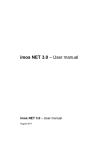
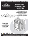
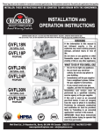
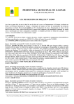
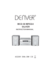
1
INSTALLER: THESE INSTRUCTIONS MUST BE CONVEYED TO AND REMAIN WITH THE HOMEOWNER
CERTIFIED UNDER AMERICAN NATIONAL STANDARDS, ANSI Z21.11.2b, VOLUME II FOR UNVENTED ROOM HEATERS.
UNVENTED MILLIVOLT SYSTEM
INSTALLATION AND OPERATION INSTRUCTIONS FOR
UNVENTED GAS FIREPLACE
GVFS60-N
MODEL GVFS60-P
NATURAL GAS MODEL
PROPANE GAS
CERTIFIED FOR THE UNITED STATES USING ANSI / AGA METHODS
WARNING: If the information in these instructions is not followed exactly, a fire or
explosion may result causing property damage, personal injury or death.
FOR YOUR SAFETY
Do not store or use gasoline or other flammable vapours and liquids in the vicinity of
this or any other appliance.
WHAT TO DO IF YOU SMELL GAS:
• Do not try to light any appliance.
• Immediately call your gas supplier from a
• Do not touch any electrical switch.
neighbour's phone. Follow the gas
• Do not use any phone in your building.
supplier's instructions.
• If you cannot reach your gas supplier, call
the fire department.
Installation and service must be performed by a qualified installer, service agency or the
gas supplier.
This is an unvented gas-fired heater that uses air (oxygen) from the room in which it is
installed. Provisions for adequate combustion and ventilation air must be provided.
Wolf Steel Ltd., RR#1, 9 Napoleon Rd.,
Barrie, ON., Canada L4M 4Y8 (705)721-1212
Fax: (705)722-6031 Email: [email protected]
Web: www.napoleon.on.ca
W415-0204 / C / 10.02.01
2
TABLE OF CONTENTS
PG 3-4
INTRODUCTION
PG 9
Warranty
General Instructions
Shipping Bracket
Mobile home installation
General Information
5
5-7
10-11
7-8
12
INSTALLATION
FINISHING
OPERATION / MAINTENANCE
Operating Instructions
Maintenance
Oxygen Depletion Sensor Pilot Cleaning
Venturi Adjustment
LOCATIONS & CLEARANCES
Combustion and Ventilation Air Provisions
Installation Examples
Gas Installation
BLOWER INSTALLATION
REPLACEMENTS
Ordering Replacement Parts
Replacement Parts
Accessories
13-14
TROUBLE SHOOTING GUIDE
Front Casting Installation
Log Placement
PLEASE RETAIN THIS MANUAL FOR FUTURE REFERENCE
WARNING
• Under no circumstances should this heater be modified.
• Provide adequate ventilation and combustion air. Provide adequate accessibility clearance for
servicing and operating the heater. Never obstruct the front opening of the heater.
• If heater shuts off, do not re-light until you provide fresh air. If heater keeps shutting off, have it
serviced. Keep burner and control compartment clean.
• Do not burn wood or other materials in this heater.
• Adults and especially children should be alerted to the hazards of high surface temperatures
and should stay away to avoid burns or clothing ignition. Supervise young children when they are
in the same room as the heater.
• Due to high temperatures, the heater should be located out of traffic and away from furniture
and draperies.
• Clothing or other flammable material should not be placed on or near the heater.
• Any safety screen or guard removed for servicing must be replaced prior to operating the heater.
• It is imperative that the control compartments, burners and circulating air passageways in the
heater are kept clean. The heater should be inspected before use and at least annually by a
qualified service person. More frequent cleaning may be required due to excessive lint from
carpeting, bedding material, etc. The heater area must be kept clear and free from combustible
materials, gasoline and other flammable vapours and liquids.
• Furniture or other objects must be kept a minimum of 4 feet away from the front of the fireplace.
• Do not use this heater if any part has been under water. Immediately call a qualified service
technician to inspect the heater and to replace any part of the control system and any gas control which has been under water.
ANY CHANGE T
O THIS HEA
TER OR ITS CONTROL
S CAN BE D
ANGEROUS AND IS PROHIBITED
TO
HEATER
CONTROLS
DANGEROUS
PROHIBITED..
W415-0204 / C / 10.02.01
3
NAPOLEON gas fireplaces are manufactured under the strict Standard of the world recognized
ISO9002 Quality Assurance Certificate.
NAPOLEON products are designed with superior components and materials, assembled by trained craftsmen who take
great pride in their work. The burner and valve assembly are leak and test-fired at a quality test station. The complete
fireplace is test-fired and thoroughly inspected by a qualified technician before packaging to ensure that you, the
customer, receives the quality product that you expect from NAPOLEON.
NAPOLEON GAS FIREPLACE PRESIDENT'S LIFETIME LIMITED WARRANTY
The following materials and workmanship in your new NAPOLEON gas fireplace are warranted against defects for
as long as you own the fireplace. This covers: combustion chamber, heat exchanger, stainless steel burner, phazer™
logs and embers, ceramic glass (thermal breakage only), gold plated parts against tarnishing, porcelainized enamelled
components and aluminum extrusion trims.
Electrical (110V and millivolt) components and wearable parts such as catalytic tiles, blowers, gas valves, thermal
switch, switches, wiring, remote controls, ignitor, gasketing, and pilot assembly are covered and NAPOLEON will
provide replacement parts free of charge during the first year of the limited warranty.
Labour related to warranty repair is covered free of charge during the first year. Repair work, however, requires
the prior approval of an authorized company official. Labour costs to the account of NAPOLEON are based on a
predetermined rate schedule and any repair work must be done through an authorized NAPOLEON dealer.
CONDITIONS AND LIMITATIONS
NAPOLEON warrants its products against manufacturing defects to the original purchaser only -- i.e., the individual or legal entity (registered customer) whose name appears on the
warranty registration card filed with NAPOLEON -- provided that the purchase was made through an authorized NAPOLEON dealer and is subject to the following conditions and limitations:
This factory warranty is nontransferable and may not be extended whatsoever by any of our representatives.
The gas fireplace must be installed by a licenced, authorized service technician or contractor. Installation must be done in accordance with the installation instructions included with the
product and all local and national building and fire codes.
This limited warranty does not cover damages caused by misuse, lack of maintenance, accident, alterations, abuse or neglect and parts installed from other manufacturers will nullify this
warranty.
This limited warranty further does not cover any scratches, dents, corrosion or discolouring caused by excessive heat, abrasive and chemical cleaners nor chipping on porcelain enamel
parts, mechanical breakage of PHAZER™ logs and embers, nor any venting components used in the installation of the fireplace.
NAPOLEON warrants its stainless steel burners against defects in workmanship and material for life, subject to the following conditions: During the first 10 years NAPOLEON will replace
or repair the defective parts at our option free of charge. From 10 years to life, NAPOLEON will provide replacement burners at 50% of the current retail price.
In the first year only, this warranty extends to the repair or replacement of warranted parts which are defective in material or workmanship provided that the product has been operated
in accordance with the operation instructions and under normal conditions.
After the first year, with respect to this President's Limited Lifetime Warranty, NAPOLEON may, at its discretion, fully discharge all obligations with respect to this warranty by refunding
to the original warranted purchaser the wholesale price of any warranted but defective part(s).
After the first year, NAPOLEON will not be responsible for installation, labour or any other costs or expenses related to the reinstallation of a warranted part, and such expenses are not
covered by this warranty.
Notwithstanding any provisions contained in this President's Limited Lifetime Warranty, NAPOLEON’S responsibility under this warranty is defined as above and it shall not in any event
extend to any incidental, consequential or indirect damages.
This warranty defines the obligations and liability of NAPOLEON with respect to the NAPOLEON gas fireplace and any other warranties expressed or implied with respect to this product,
its components or accessories are excluded.
NAPOLEON neither assumes, nor authorizes any third party to assume, on its behalf, any other liabilities with respect to the sale of this product. NAPOLEON will not be responsible for:
over-firing, downdrafts, spillage caused by environmental conditions such as rooftops, buildings, nearby trees, hills, mountains, inadequate vents or ventilation, excessive venting configurations, insufficient makeup air, or negative air pressures which may or may not be caused by mechanical systems such as exhaust fans, furnaces, clothes dryers, etc.
Any damages to fireplace, combustion chamber, heat exchanger, brass trim or other component due to water, weather damage, long periods of dampness, condensation, damaging
chemicals or cleaners will not be the responsibility of NAPOLEON.
The bill of sale or copy will be required together with a serial number and a model number when making any warranty claims from your authorized dealer. The warranty registration card
must be returned within fourteen days to register the warranty.
NAPOLEON reserves the right to have its representative inspect any product or part thereof prior to honouring any warranty claim.
ALL SPECIFICATIONS AND DESIGNS ARE SUBJECT TO CHANGE WITHOUT PRIOR NOTICE DUE TO ON-GOING PRODUCT IMPROVEMENTS. NAPOLEON® IS A REGISTERED
TRADEMARK OF WOLF STEEL LTD. PATENTS U.S. 5.303.693.801 - CAN. 2.073.411, 2.082.915. © WOLF STEEL LTD.
NOTE: Changes, other than editorial, are denoted by a vertical line in the margin.
W415-0204 / C / 10.02.01
4
GENERAL INSTRUCTIONS
THIS GAS FIREPLACE SHOULD BE INSTALLED AND
SERVICED BY A QUALIFIED INSTALLER to conform with
local codes. In absence of local codes, install the GVFS60
to the current National Fuel Gas Code, ANSI Z223.1 Installation Code which can be obtained from:
American Nation Standards Institute Inc.
1430 Broadway
New York, NY 10018
or
National Fire Protection Association Inc.
Batterymarch Park
Quincy, MA 02269
The fireplace and its individual shutoff valve must be disconnected from the gas supply piping system during any
pressure testing of that system at test pressures in excess of ½ psig (3.5 kPa). The fireplace must be isolated
from the gas supply piping system by closing its individual
manual shutoff valve during any pressure testing of the
gas supply piping system at test pressures equal to or
less than ½ psig (3.5 kPa).
The stove, when installed with a blower, must be electrically connected and grounded in accordance with local
codes. In the absence of local codes, use the current
ANSI/NFPA 70-1996 NATIONAL ELECTRICAL CODE. The
blower power cord must be connected into a properly
grounded receptacle. The grounding prong must not be
removed from the cord plug.
SHIPPING BRACKET
To avoid the stove being damaged during shipping, a shipping bracket has been used and must be unbolted before
the stove can be installed.
1. Remove the four nuts holding the shipping bracket to
the bottom of the stove.
2. Lift the stove up and away from the skid to clear the
threaded bolts sticking through the bracket. Set down on a
flat surface. The stove top is not secured to the unit.
3. Discard the nuts, bracket and the skid.
4 NUTS
SHIPPING
BRACKET
MOBILE HOME INSTALLATION
Suitable for mobile home installation where the mobile
home has been permanently placed on its site.
This fireplace may be installed in an aftermarket permanently located, manufactured (mobile) home, where
not prohibited by local codes.
For mobile home installations, the fireplace must be fastened in place. It is recommended that the fireplace be
secured in all installations. Use the levelling / securing kit,
GDSLL-KT, for this purpose.
GENERAL INFORMATION
FOR YOUR SATISFACTION, THIS FIREPLACE HAS BEEN
TEST-FIRED TO ASSURE ITS OPERATION AND QUALITY! Maximum input is 30,000 BTU/hr for natural gas and
propane. When the fireplace is installed at elevations above
2,000ft, and in the absence of specific recommendations
from the local authority having jurisdiction, the certified
high altitude input rating shall be reduced at the rate of 4%
for each additional 1,000ft.
This heater must not be installed in a bedroom or bathroom.
This fireplace is only for use with the type of gas indicated on the rating plate. This fireplace is not convertible for use with other gases, unless a certified kit is
used.
Minimum inlet gas supply pressure is 4.5 inches water
column for natural gas and 11 inches water column for
propane. Maximum inlet gas pressure is 7 inches water
column for natural gas and 13 inches water column for
propane. Manifold pressure under flow conditions is 3.5
inches water column for natural gas and 10 inches water
column for propane.
No external electricity (110 volts or 24 volts) is required
for the gas system operation. Expansion / contraction
noises during heating up and cooling down cycles are
normal and are to be expected.
This heater is equipped with a pilot light safety
system referred to as an OXYGEN DEPLETION
SENSOR and is designed to turn off the heater
if not enough fresh air is available.
Use only accessories designed for and listed
with your specific fireplace.
CARBON MONOXIDE POISONING
MAY LEAD TO DEATH
Early signs of carbon monoxide poisoning resemble the flu, with headache, dizziness and/
or nausea. If you have these signs, the heater
may not be working properly. Get fresh air at
once! Have heater serviced.
FIGURE 1
W415-0204 / C / 10.02.01
Some people---pregnant women, persons
with heart or lung disease, anemia, those under the influence of alcohol, those at high altitudes--- are more affected by carbon monoxide than others.
5
LOCATION AND CLEARANCES
Provide adequate ventilation and combustion air.
Provide adequate accessibility clearance for servicing and operating the stove.
MAINTAIN THESE MINIMUM CLEARANCES TO
COMBUSTIBLES:
Never obstruct the front opening of the stove.
As long as clearance to combustibles is kept within the
required distances, the most desirable and beneficial location for a Napoleon stove is in the centre of a building,
thereby allowing the most efficient use of the heat created.
The location of windows, doors and the traffic flow in the
room where the stove is to be located should be considered.
FIGURE 3
A. 6"
15½"
C. 2"*
NO ADDITIONAL FLOOR PROTECTION IS REQUIRED.
MINIMUM 46" FROM STOVE TOP TO CEILING.
* AT A DISTANCE OF 2” FROM THE WALL, ACCESS TO THE BLOWER
SWITCH, ON-OFF SWITCH OR THE BLOWER POWER CORD MAY
NOT BE PRACTICAL.
29 7/8"
25½"
B. 6"
FIGURE 2
INSTALL ATION
COMBUSTION AND VENTILATION
AIR PROVISIONS
This heater shall not be installed in a confined space or
unusually tight construction unless provisions are provided for adequate combustion and ventilation air.
This fireplace must be installed against a finished wall.
Do not install against a vapour barrier or exposed insulation.
The National Fuel Gas Code, ANSI Z223.1 defines a confined space as a space whose volume is less than 50
cubic feet per 1,000 Btu per hour (4.8 m3 per kw) of the
aggregate input rating of all appliances installed in that
space and an unconfined space as a space whose volume is not less than 50 cubic feet per 1,000 Btu per hour
(4.8 m3 per kw) of the aggregate input rating of all appliances installed in that space. Rooms communicating directly with the space in which the appliances are installed,
through openings not furnished with doors are considered a part of the unconfined space.
DETERMINING CONFINED OR UNCONFINED SPACE:
To determine the volume of the room where the heater is
to be installed, multiply the width x the length x the ceiling
height of that room measured in feet. If any adjoining rooms
are connected by grills or openings such as kitchen passthroughs, etc., the volume of those rooms may be added
to the total.
Multiply the room volume by 1000 and divide this amount
by 50 to determine the maximum Btu/hr that the space can
support with adequate combustion and ventilation air.
Add the Btu/hr of all fuel burning appliances located within
the space such as gas furnace, gas water heater, etc. Do
not include direct vent gas appliances which draw their
input and output air from and to the outdoors.
WARNING: If the area in which the heater may be operated
is smaller than that defined as an unconfined space or if
the building is of unusually tight construction, provide
adequate combustion and ventilation air by one of the
methods described in the National Fuel Gas Code
ANSI Z223.1, Section 5.3 or the applicable local code.
The GVFS60 is rated at 30,000BTUs per hour and
therefore requires a minimum unconfined space
of 1,500 cubic feet.
W415-0204 / C / 10.02.01
6
Room Volume = Length x Width x Height
Max BTU/hr = Room Volume x 1000 ÷ 50
ROOM 2
ROOM 1
FIGURE 4
HEIGHT
LENGTH
W
ID
H
T
If for example,
the length of the rooms is 10 feet,
the width of Room 1 is 10 feet,
the width of Room 2 is 15 feet
the height of the rooms is 8 feet.
The volume of Room 1: 10 x 10 x 8 = 800 cubic feet.
The volume of Room 2: 10 x 15 x 8 = 1200 cubic feet.
EXAMPLE 1
In this example, because there is no door to the adjoining
room, the volume of the adjoining room may be added to
the volume of the room with the heater to get a total
unconfined space.
The total unconfined space: 800 + 1200 = 2000 cubic feet.
Maximum BTU/h:
2000 x 1000
50
= 40,000 BTU/h
If there are no more fuel burning appliances within this
space then the 30,000 BTU/h input of the fireplace is suitable to be installed. This also assumes that the construction of this space is not unusually tight.
EXAMPLE 2
If in this example a solid door separates Room 1 from
Room 2, the volume of Room 2 could not be used. In this
case the maximum BTU/h would be:
Maximum BTU/h:
800 x 1000
50
= 16,000 BTU/h
This would be considered a confined space since it can
not support the 30,000BTU/h input of the heater and it
would be necessary to provide adequate combustion and
ventilation air to Room 1.
Unusually tight construction is defined as construction where:
a) Walls and ceilings exposed to the outside atmosphere have a continuous water vapour retarder with a
rating of 1 perm (6 x 10-11 kg per pa-sec-m2) or less with
openings gasketed or sealed, and
b) Weather stripping has been added on openable
windows and doors, and
c) Caulking or sealants are applied to areas such as
joints around window and door frames, between sole
plates and floors, between wall-ceiling joints, between
wall panels, at penetrations for plumbing, electrical, and
gas lines, and at other openings.
An unvented room heater is recommended for use as a
secondary heat source rather than as a primary source.
Gas combustion produces water vapour which could occur at the rate of approximately one ounce of water for
every 1,000 BTU/hr of gas input. During the cold weather
season, indoor humidity levels tend to be low. Consequently, this water vapour can enhance the living space.
However if a problem should occur:
a) ensure sufficient combustion and circulation air
b) use a dehumidifier
c) do not use the unvented room heater as a primary
heat source
Without sufficient fresh air for proper operation, poor fuel
combustion can result. Carbon Monoxide is a result of
poor combustion.
If additional fresh air is required, use one of the
methods described in the National Fuel Gas Code,
ANSI Z223.1, Section 5.3 or the applicable local code.
W415-0204 / C / 10.02.01
7
Attach the two leads to terminals 1 and 3 located on the
gas valve.
O
ON
FF
FIGURE 6
1
2
PL T
DO NOT KINK FLEX CONNECTOR.
LO
1. Move the stove into position. We recommend securing the stove to the floor, in all cases. Levelling / securing
kit GDSLL-KT may be used for this purpose.
2. Install rigid black pipe, 1/2" type-L copper tubing or, if
local codes permit, a 3/8" flex connector and shutoff valve
to the gas line and the fireplace gas valve. Seal and tighten
securely. An adapter fitting is required between the gas
valve and the copper tubing or flex connector.
4. For ease of accessibility, an optional remote wall
switch or millivolt thermostat may be installed in a convenient location. Route a 2 strand, solid core millivolt wire
from the stove to the wall switch or millivolt thermostat.
The recommended maximum lead length depends on
wire size:
WIRE SIZE
MAX. LENGTH
14 gauge
100 feet
16 gauge
60 feet
18 gauge
40 feet
IH
GAS INSTALLATION
O I
FIGURE 5
3. Check for gas leaks by brushing on a soap and water
solution.
DO NOT USE OPEN FLAME.
PI L OT
3
DO NOT CONNECT EITHER THE WALL SWITCH, THERMOSTAT OR GAS VALVE TO ELECTRICITY (110
VOLTS).
It is not necessary to install a hearth extension with this
fireplace system. Objects placed in front of the fireplace
should be kept a minimum of 4 feet away from the front
face.
FINISHING
FRONT CAST INSTALLATION
TOP
FIGURE 7b
CAST FRONT
SECURING BOLTS
RETAINER
MESH
SECURING
BOLTS
FIGURE 7a
FRONT
2. Lift the top casting off
the unit.
3. Fit the securing bolts
on the cast front into each
of the respective retainer
brackets (located at either side on the top). Insert and tighten the securing screw from the
bottom up (located at the
lower center behind the
cast front). This will hold
the cast front in place.
Replace the top casting.
4. To remove the front,
repeat in reverse order.
1. Place the cast front face down on a protective surface
such as a carpet or blanket to avoid scratching the finished surface. Attach the screen to the inside of the front
using four bolts and washers.
FIGURE 7c
SECURING
SCREW
W415-0204 / C / 10.02.01
8
LOG PLACEMENT INSTRUCTIONS
Blocked burner ports can cause an incorrect flame pattern, carbon deposits and delayed ignition. PHAZERTM logs
glow when exposed to direct flame and provide a unique
and realistic glowing effect. Use only certified PHAZERTM
logs available from your Napoleon / Wolf Steel Ltd. dealer.
The notch in log #5 should be pressed down onto the
skewering pin located at the end of the grate as shown to
prevent it from rocking.
3
#6
1
FIGURES 8a-d
#1
#3
#4
Position the notch located in log #6 against the grate post.
4
#2
Place log #1 onto the burner, centering it onto the burner
tray and pushing it as close to the rear wall of the firebox
as possible. Move logs # 2 and 3 into position, lining up
the studs located on the burner with the holes on the bottom of the logs. Sit the notch at the bottom of log #4 against
the left outermost grate post and position the top of the log
into the pocket provided on the rear log (#1).
2
#5
#7
Place the bottom of log #7 against the right outermost
grate post and the top into the pocket provided on the center
log (#6). Tear the glowing embers into pieces and place
onto the front of the burner. Care should be taken to shred
the embers into thin, small irregular pieces as only the
exposed edges of the fibre hairs will glow when exposed
to direct flame; however care should be taken to not block
the burner ports. Blocked ports can cause an incorrect
flame pattern, carbon deposits and delayed ignition.
Log colours may vary. During the initial use of the fireplace, the colours will become more uniform as colour
pigments burn in during the heat activated curing process.
POSITIONING THE LOGS IMPROPERLY WILL CAUSE
FLAME IMPINGEMENT AND CARBONING.
W415-0204 / C / 10.02.01
9
BLOWER INSTALLATION
ON/OFF SWITCH BRACKET
4. Remove the 2 screws from the top outer edge of the rear
stove panel. The housing is mounted using these two
holes, as well as two other holes located in the rear panel.
5. Mount and secure the blower housing using 4 screws.
Ensure that the on/off switch wires pass through the appropriate slot located on either side of the blower housing.
6. Remove the 2 screws from the side of the blower housing
that you want the switch to be located on and re-secure the
on/off switch.
COVER PLATE
ACCESS PLATE
FIGURE 9
1. Ensure that the access cover plate has been installed.
2. Remove the on/off switch bracket and the cover plate
below it. The cover plate may now be discarded.
3. Decide which side of the blower housing you prefer the
on/off switch to be located on.
SLOT
FIGURE 11
Because the blower is thermally activated, when
turned on, it will automatically start approximately
15-30 minutes after lighting the stove and will run
for approximately 30-45 minutes after the stove has
been turned off. Use of the fan increases the output of heat.
Drywall dust will penetrate into the blower bearings, causing irreparable damage. Care must be
taken to prevent drywall dust from coming into
contact with the blower or its compartment. Any
damage resulting from this condition is not covered by the warranty policy.
REMOVED SCREWS
FIGURE 10
W415-0204 / C / 10.02.01
10
OPERATION / MAINTENANCE
OPERATING INSTRUCTIONS
If heater shuts off, do not relight until you provide
fresh air. If heater keeps shutting off, have it serviced. Keep burner and control compartment
clean.
When lit for the first time, the fireplace will emit a slight
odour for a few hours. This is a normal temporary condition caused by the curing of the logs and the "burn-in" of
internal paints and lubricants used in the manufacturing
process and will not occur again. After extended periods
of non-operation such as following a vacation or a warm
weather season, the fireplace may emit a slight odour for
a few hours. This is caused by dust particles burning off.
In both cases, open a window to sufficiently ventilate the
room.
FOR YOUR SAFETY READ BEFORE OPERATING
WARNING: IF YOU DO NOT FOLLOW THESE INSTRUCTIONS EXACTLY, A FIRE OR EXPLOSION MAY RESULT CAUSING PROPERTY DAMAGE, PERSONAL INJURY OR LOSS OF LIFE.
ON
FF
P
O
C. Use only your hand to push in and turn the gas control
knob. Never use tools. If the knob will not push in and
turn by hand, do not try to repair it. Call a qualified service
technician. Force or attempted repair may result in a fire
or explosion.
D. Do not use this fireplace if any part has been under water. Immediately call a qualified service technician to inspect the fireplace and replace any part of the control system and any gas control which has been under water.
WHAT TO DO IF YOU SMELL GAS:
• Do not try to light any appliance.
• Do not touch any electric switch; do not use any phone
in your building.
• Immediately call your gas supplier from a neighbour's
phone. Follow the gas supplier's instructions.
• If you cannot reach your gas supplier, call the fire
department.
L T
O I
A. This fireplace is equipped with a pilot which must be lit
by hand while following these instructions exactly.
B. Before operating smell all around the fireplace area for
gas and next to the floor because some gas is heavier
than air and will settle on the floor.
OXYGEN DEPLETION SENSOR
GAS KNOB
LIGHTING INSTRUCTIONS
GAS KNOB AT OFF
O
ON
FF
PLT
STOP! Read the above safety information on this label.
Set the thermostat to lowest setting.
Turn off all electric power to the fireplace.
Open the control door. Turn the gas knob clockwise
to off.
5. Wait five (5) minutes to clear out any gas. If you smell
gas including near the floor, STOP! Follow "B" in the
above safety information on this label. If you don't smell
gas go to the next step.
6. Find pilot located in front of the back log.
7. Turn gas knob counter-clockwise
to pilot.
LO
1.
2.
3.
4.
8. Depress and hold gas knob while lighting the pilot
with the push button ignitor. Keep knob fully depressed
for one minute, then release. If pilot does not continue
to burn repeat steps 3 through 7.
to
9. With pilot lit, turn gas knob counter-clockwise
on.
10. If equipped with remote on-off switch, main burner
may not come on when you turn the valve to on. Remote switch must be in the on position to ignite burner.
11. Turn on all electric power to the fireplace.
IH
When lighting and re-lighting, the gas knob cannot be
turned from pilot to off unless the knob is depressed.
O I
PI L OT
TO TURN OFF GAS
1. Turn off all electric power to the fireplace if service is to
be performed.
W415-0204 / C / 10.02.01
2. Push in gas control knob slightly and turn clockwise
to off. Do not force.
11
MAINTENANCE
TURN OFF THE GAS AND ELECTRICAL POWER
BEFORE SERVICING THE FIREPLACE.
CAUTION: Label all wires prior to disconnection when
servicing controls. Wiring errors can cause improper and
dangerous operation. Verify proper operation after servicing. This heater should be inspected and serviced before
use and at least annually by a qualified service person.
The fireplace area must be kept clear and free of combustible materials, gasoline or other flammable vapours and
liquids. The flow of combustion and ventilation air must
not be obstructed.
1. In order to properly clean the burner and oxygen depletion sensor system, remove the logs to expose both assemblies.
2. Keep the control compartment, logs, burner, air shutter
opening and the area surrounding the logs clean by vacuuming or brushing, at least once a year.
3. Check to see that all burner ports are burning. Clean
out any of the ports which may not be burning or are not
burning properly.
4. Check to see that the pilot flame is large enough to
engulf the thermocouple and thermopile and promptly ignites the main burner.
5. Replace the cleaned logs.
6. Check to see that the main burner ignites completely
on all openings when the gas knob for the burner is turned
on. A 5 to 10 second total light-up period is satisfactory. If
ignition takes longer, consult your Napoleon dealer / distributor.
OXYGEN DEPLETION SENSOR PILOT
CLEANING
This procedure must be performed by a qualified
service person!
Inspect the pilot for any visible contamination or debris
(usually lint, pet hair, spider webs, carpet fibre, etc.) and
remove.
Disconnect the pilot from the pilot tubing line. Using a 7/16”
wrench, remove the injector from the pilot housing. Blow
out the housing in the same direction as the gas flow.
Re-install the injector and the pilot tube, turn on the gas
and check for leaks.
If this does not improve the performance, replace the pilot
with an exact replacement. The device is tamper resistant with no field serviceable parts.
CORRECT PILOT
FLAME
INCORRECT PILOT
FLAME
VENTURI ADJUSTMENT
Air shutter adjustment must only be done by a
qualified gas installer!
Closing the air shutter will cause a more yellow flame, but
can lead to carboning. Opening the air shutter will cause a
more blue flame, but can cause flame lifting from the burner
ports. The flame may not appear yellow immediately; allow 15 to 30 minutes for the final flame colour to be established.
Opening the air shutter will also reduce exhaust odours
smelled within the room. See Trouble Shooting Guide.
AIR SHUTTER OPENINGS
NG
5/16" (0.313)
LP
5/16" (0.313)
W415-0204 / C / 10.02.01
12
REPLACEMENTS
ORDERING REPLACEMENT PARTS
Contact your dealer or the factory for questions concerning prices and policies on replacement parts. Normally all
parts can be ordered through your Napoleon dealer or
distributor. When ordering replacement parts always give
the following information:
1. MODEL & SERIAL NUMBER OF FIREPLACE
2. INSTALLATION DATE OF FIREPLACE
3. PART NUMBER
4. DESCRIPTION OF PART
5. FINISH
O
LO
ON
FF
P L T
IH
O I
PI LOT
W725-030
W725-031
W361-0016
REPLACEMENT PARTS
For warranty replacement parts, a photocopy of the original invoice will be required to honour the claim.
W550-0001
PART #
DESCRIPTION
REPLACEMENT PARTS:
W725-0030
W725-0031
W010-0757
W455-0026
N455-0003
W662-0001
W662-0002
W680-0004
W357-0001
GL-624
W135-0094
W135-0082
W135-0076
W135-0096
W135-0078
W135-0093
W135-0095
W361-0016
W385-0045
W660-0009
W690-0002
W565-0038
GS830-K
W135-0069*
W135-0073*
W135-0068*
W135-0074
F_E*
EARLY AMERICAN
SIT VALVE - NG
SIT VALVE - LP
BURNER
#38 BURNER ORIFICE - NG
#52 BURNER ORIFICE - LP
OXYGEN DEPLETION SENSOR SYSTEM - NG
#6- W135-0093
OXYGEN DEPLETION SENSOR SYSTEM - LP
THERMOPILE
PIEZO IGNITOR
#7 - W135-0095
LOG SET CW EMBERS
LOG #1
#1 - W135-0094
CHARCOAL PIECE (LOG #2)
LOG #3
LOG #4
LOG #5
LOG #6
LOG #7
#4 W135-0096
GLOWING EMBERS
NAPOLEON LOGO
ON/OFF SWITCH
THERMODISC
SCREEN
#2 - W135-0082
BLACK TRIVET
SIDE (LEFT OR RIGHT)
#5 - W135-0078
#3 - W135-0076
TOP
LEG EA.
BASE PAINT FINISH ONLY
ACCESSORIES / OPTIONS
W690-0001
W690-0002
W690-0010
W690-0011
GDSLL-KT
GS-SSV *
GS-64KT
GS830-G
GS830-C
W550-0001
W380-0002
KB-35
F_E*
* FOR
MILLIVOLT THERMOSTAT
HAND-HELD REMOTE
REMOTE CONTROL - ADVANTAGE
REMOTE CONTROL - ADVANTAGE PLUS
LEVELLING / SECURING KIT
CAST SIDE SHELVES - LEFT & RIGHT
BLOWER KIT
GOLD TRIVET
CHROME TRIVET
CHARCOAL EMBERS
VARIABLE SPEED SWITCH KNOB
VARIABLE SPEED SWITCH
EARLY AMERICAN FRONT
W662-0001
W662-0002
W565-0038
GS830-K / G / C
AVAILABLE PORCELAIN COLOURS , ADD THESE LETTERS TO THE BASE PART
NUMBER:
BROWN
ALMOND
BLUE
BLACK
GREEN
-
N
S
B
GS-64KT
K
F
W415-0204 / C / 10.02.01
GS-SSV
13
TROUBLE SHOOTING GUIDE
SYMPTOM
PROBLEM
TEST SOLUTION
Main burner goes Pilot flame is not large - service or replace Oxygen Depletion Sensor System
out; pilot stays on. enough or not engulfing the - correct piping and/or regulator to provide correct pressure
thermopile
Thermopile shorting
- clean thermopile connection to the valve. Reconnect.
- replace Oxygen Depletion Sensor System / valve.
Remote wall switch wire is - shorten wire to correct length or wire gauge.
too long; too much resistance in the system.
Faulty thermostat or switch.
Main burner goes Insufficient air supply
out; pilot goes out.
Out of propane gas.
- replace.
- open window or door. (Use one of the methods described in ANSI
Z223.1 Section 5.3 or the applicable local code.)
- fill the tank.
Pilot flame is not large - service or replace Oxygen Depletion Sensor System
enough. (Supply pressure - correct piping and / or regulator to provide correct pressure.
too low.)
Pilot goes out when
the gas knob is released.
The gas valve has
an interlock device
which will not allow
the pilot burner to
be lit until the thermocouple
has
cooled. Allow approximately 60
seconds for the
thermocouple to
cool.
Pilot burning; no
gas
to
main
burner; gas knob
is on 'HI'; wall
switch / thermostat
is on.
System is not correctly - purge the gas line.
purged.
Out of propane gas.
Pilot flame is not large - service or replace Oxygen Depletion Sensor System
enough. (Supply pressure
too low.)
Thermocouple shorting / faulty.
Faulty valve.
- replace.
Wall switch wiring is defec- - disconnect wires from valve. Connect a jumper wire across termitive.
nals 1 & 3; if the main burner lights, check the wires for defects and
/ or replace wires.
Main burner orifice is plugged.
- remove stoppage in orifice.
Faulty valve.
- replace.
No spark at pilot burner
THERMOPILE
PILOT
BURNER
ELECTRODE
loosen and tighten thermocouple.
clean thermocouple and valve connection.
replace Oxygen Depletion Sensor System
test and replace valve.
Themostat or switch is de- - connect a jumper wire across the wall switch terminals; if main
burner lights, replace switch / thermostat.
fective.
Pilot will not light. Out of propane gas
THERMOCOUPLE
- fill the tank.
No gas at the pilot burner
- fill the tank.
-
check if pilot can be lit by a match
check that the wire is connected to the push button ignitor.
check if the push button ignitor needs tightening.
replace the wire if the wire insulation is broken or frayed.
replace the electrode if the ceramic insulator is cracked or broken.
replace the push button ignitor.
-
check that the manual valve is turned on.
check the pilot orifice for blockage.
replace the valve / Oxygen Depletion Sensor System.
call the gas distributor.
W415-0204 / C / 10.02.01
14
SYMPTOM
PROBLEM
Pilot goes out Gas piping is undersized.
while standing;
Main burner is in
'OFF' position.
TEST SOLUTION
- turn on all gas appliances and see if pilot flame flutters, diminishes or extinguishes, especially when main burner ignites. Monitor
appliance supply working pressure.
- check if supply piping size is to code. Correct all undersized piping.
Flames are con- Unit is over-fired or under- - check pressure readings:
sistently too large fired.
Inlet pressure can be checked by turning screw (A) counter-clockor too small.
wise 2 or 3 turns and then placing pressure gauge tubing over the
B
A
Carboning occurs.
test point. Check with burner operating on "HI". Gauge should read
7" (minimum 4.5") water column for natural gas or 13" (11" minimum) water column for propane.
Outlet pressure can be checked the same as above using screw
(B). Check with burner operating on "HI". Gauge should read 3.5"
water column for natural gas or 10" water column for propane.
I
O
AFTER TAKING PRESSURE READINGS, BE SURE TO TURN
SCREWS CLOCKWISE FIRMLY TO RESEAL. DO NOT OVERTORQUE.
Leak test with a soap and water solution.
O
LO
ON
FF
PL T
IH
PI L OT
Carbon is being Air shutter has become - ensure air shutter opening is free of lint or other obstructions.
deposited on logs blocked
or
combustion
- check that the logs are correctly positioned.
chamber surfaces. Flame is impinging on the
logs or combustion cham- open air shutter to increase the primary air. See air shutter openber.
ings, page 15.
- check the input rate: check the manifold pressure and orifice size
as specified by the rating plate values.
Exhaust fumes
smelled in room,
headaches.
Remote
wall
switch is in "OFF"
position;
main
burner comes on
when gas knob is
turned to "ON" position.
W415-0204 / C / 10.02.01
Not enough combustion air. - increase fresh air supply. (Use one of the methods described in
ANSI Z223.1 Section 5.3 or the applicable local code.)
Not enough ventilation air.
- increase fresh air supply. (Use one of the methods described in
ANSI Z223.1 Section 5.3 or the applicable local code.)
Flame is impinging on the
logs or combustion chamber.
- check that the logs are correctly positioned.
- open air shutter to increase the primary air. See air shutter openings, page 15.
- check the input rate: check the manifold pressure and orifice size
as specified by the rating plate values.
Wall switch is mounted up- - reverse.
side down
Remote wall switch is - replace.
grounding.
Remote wall switch wire is - check for ground (short); repair ground or replace wire.
grounding.
- replace.
Faulty valve.
Wolf Steel Fireplace Service History
This fireplace must be serviced annually depending on usage.
Date
Dealer Name
Service Technician
Name
Service Performed
Special Concerns
15
W415-0204 / C / 10.02.01
16
NOTES:
W415-0204 / C / 10.02.01