1
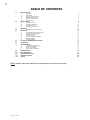
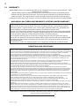
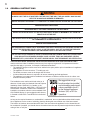
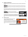
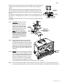
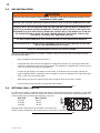
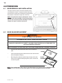
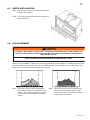
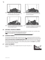
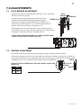
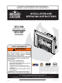
1 INSTALLER: LEAVE THIS MANUAL WITH THE APPLIANCE. CONSUMER: RETAIN THIS MANUAL FOR FUTURE REFERENCE. INSTALLATION AND OPERATING INSTRUCTIONS CERTIFIED UNDER CANADIAN AND AMERICAN NATIONAL STANDARDS: CSA 2.33, ANSI Z21.88 FOR VENTED GAS FIREPLACE HEATERS. GDI-30N NATURAL GAS GDI-30P PROPANE CERTIFIED FOR CANADA AND UNITED STATES USING ANSI/CSA METHODS. SAFETY INFORMATION ! WARNING If the information in these instructions are not followed exactly, a fire or explosion may result causing property damage, personal injury or loss of life. - Do not store or use gasoline or other flammable vapors and liquids in the vicinity of this or any other appliance. - WHAT TO DO IF YOU SMELL GAS: • Do not try to light any appliance. • Do not touch any electrical switch; do not use any phone in your building. • Immediately call your gas supplier from a neighbour’s phone. Follow the gas supplier’s instructions. • If you cannot reach your gas supplier, call the fire department. - Installation and service must be performed by a qualified installer, service agency or the supplier. Wolf Steel Ltd., 24 Napoleon Rd., Barrie, ON, L4M 4Y8 Canada / 103 Miller Drive, Crittenden, Kentucky, USA, 41030 Phone (705)721-1212 • Fax (705)722-6031 • www.napoleonfireplaces.com • [email protected] 1.2 $10.00 W415-0806 / 06.28.09 2 TABLE OF CONTENTS 1.0 2.0 INTRODUCTION 3 1.1 1.2 1.3 1.4 1.5 1.6 4 5 5 6 7 7 INSTALLATION 2.1 2.2 2.3 2.4 3.0 5.0 6.0 7.0 8.0 9.0 10.0 11.0 12.0 INSERT LEVELLING CHIMNEY CONNECTION GAS INSTALLATION OPTIONAL WALL SWITCH FRAMING 3.1 4.0 WARRANTY DIMENSIONS INSTALLATION OVERVIEW GENERAL INSTRUCTIONS GENERAL INFORMATION CARE OF GLASS MINIMUM MANTEL CLEARANCES 8 8 10 10 11 11 FINISHING 12 4.1 4.2 4.3 4.4 4.5 4.6 4.7 12 12 13 13 14 14 14 DOOR REMOVAL AND INSTALLATION DOOR GLASS REPLACEMENT GRATE INSTALLATION LOG PLACEMENT OPTIONAL CHARCOAL EMBERS GLOWING EMBERS LOGO PLACEMENT OPTIONAL BLOWER INSTALLATION OPERATION ADJUSTMENTS 15 16 17 7.1 7.2 7.3 7.4 17 17 18 18 PILOT BURNER ADJUSTMENT VENTURI ADJUSTMENT FLAME ADJUSTMENT FLAME CHARACTERISTICS MAINTENANCE REPLACEMENTS TROUBLE SHOOTING SERVICE HISTORY NOTES NOTE: changes, other than editorial, are denoted by a vertical line in the margin. W415-0806 / 06.28.09 8 18 19 23 25 26 3 1.0 INTRODUCTION ! • • • • • • • • • • • • • • • • • • • • • • • • • WARNING Do not operate appliance before reading and understanding operating instructions. Failure to operate appliance according to operating instructions could cause fire or injury. Risk of fire or asphyxiation do not operate appliance with fixed glass removed. Do not connect 110 volts to the control valve. Risk of burns. The appliance should be turned off and cooled before servicing. Do not install damaged, incomplete or substitute components. Risk of cuts and abrasions. Wear protective gloves and safety glasses during installation. Sheet metal edges may be sharp. Do not burn wood or other materials in this appliance. Young children should be carefully supervised when they are in the same room as the appliance. Toddlers, young children and others may be susceptible to accidental contact burns. A physical barrier is recommended if there are at risk individuals in the house. To restrict access to an appliance or stove, install an adjustable safety gate to keep toddlers, young children and other at risk individuals out of the room and away from hot surfaces. Clothing or other flammable material should not be placed on or near the appliance. Due to high temperatures, the appliance should be located out of traffic and away from furniture and draperies. Ensure you have incorporated adequate safety measure to protect infants/toddlers from touching hot surfaces. Even after the appliance is out, the glass and/or screen will remain hot for an extended period of time. Check with your local hearth specialty dealer for safety screens and hearth guards to protect children from hot surfaces. These screens and guards must be fastened to the floor. Any safety screen or guard removed for servicing must be replaced prior to operating the appliance. It is imperative that the control compartments, burners and circulating blower and its passageway in the appliance and venting system are kept clean. The appliance and its venting system should be inspected before use and at least annually by a qualified service person. More frequent cleaning may be required due to excessive lint from carpeting, bedding material, etc. The appliance area must be kept clear and free from combustible materials, gasoline and other flammable vapors and liquids. Under no circumstances should this appliance be modified. This appliance must not be connected to a chimney flue pipe serving a separate solid fuel burning appliance. Do not use this appliance if any part has been under water. Immediately call a qualified service technician to inspect the appliance and to replace any part of the control system and any gas control which has been under water. Do not operate the appliance with the glass door removed, cracked or broken. Replacement of the glass should be done by a licensed or qualified service person. Do not strike or slam shut the appliance glass door. This appliance uses and requires a fast acting thermocouple. Replace only with a fast acting thermocouple supplied by Wolf Steel Ltd. Pressure relief doors must be kept closed while the appliance is operating to prevent exhaust fumes containing carbon monoxide, from entering into the home. Temperatures of the exhaust escaping through these openings can also cause the surrounding combustible materials to overheat and catch fire. Only doors / optional fronts certified with the unit are to be installed on the appliance. Keep the packaging material out of reach of children and dispose of the material in a safe manner. As with all plastic bags, these are not toys and should be kept away from children and infants. As with any combustion appliance, we recommend having your appliance regularly inspected and serviced as well as having a Carbon Monoxide Detector installed in the same area to defend you and your family against Carbon Monoxide. 3.1 W415-0806 / 06.28.09 4 1.1 WARRANTY NAPOLEON® products are manufactured under the strict Standard of the world recognized ISO 9001 : 2000 Quality Assurance Certificate. NAPOLEON® products are designed with superior components and materials assembled by trained craftsmen who take great pride in their work. The burner and valve assembly are leak and test-fired at a quality test station. The complete heater is again thoroughly inspected by a qualified technician before packaging to ensure that you, the customer, receives the quality product that you expect from NAPOLEON®. NAPOLEON® GAS FIREPLACE PRESIDENT’S LIFETIME LIMITED WARRANTY The following materials and workmanship in your new NAPOLEON® gas heater are warranted against defects for as long as you own the heater. This covers: combustion chamber, heat exchanger, stainless steel burner, phazer™ logs and embers, rocks, ceramic glass (thermal breakage only), gold plated parts against tarnishing, porcelainized enameled components and aluminum extrusion trims.* Electrical (110V and millivolt) components and wearable parts such as blowers, gas valves, thermal switch, switches, wiring, remote controls, ignitor, gasketing, and pilot assembly are covered and NAPOLEON® will provide replacement parts free of charge during the first year of the limited warranty.* Labour related to warranty repair is covered free of charge during the first year. Repair work, however, requires the prior approval of an authorized company official. Labour costs to the account of NAPOLEON® are based on a predetermined rate schedule and any repair work must be done through an authorized NAPOLEON® dealer. * Construction of models vary. Warranty applies only to components included with your specific heater. CONDITIONS AND LIMITATIONS NAPOLEON® warrants its products against manufacturing defects to the original purchaser only. Registering your warranty is not necessary. Simply provide your proof of purchase along with the model and serial number to make a warranty claim. NAPOLEON® reserves the right to have its representative inspect any product or part thereof prior to honouring any warranty claim. Provided that the purchase was made through an authorized NAPOLEON® dealer your heater is subject to the following conditions and limitations: This factory warranty is non-transferable and may not be extended whatsoever by any of our representatives. The gas heater must be installed by a licensed, authorized service technician or contractor. Installation must be done in accordance with the installation instructions included with the product and all local and national building and fire codes. This limited warranty does not cover damages caused by misuse, lack of maintenance, accident, alterations, abuse or neglect and parts installed from other manufacturers will nullify this warranty. This limited warranty further does not cover any scratches, dents, corrosion or discoloring caused by excessive heat, abrasive and chemical cleaners nor chipping on porcelain enamel parts, mechanical breakage of PHAZER™ logs and embers. NAPOLEON® warrants its stainless steel burners against defects in workmanship and material for life, subject to the following conditions: During the first 10 years NAPOLEON® will replace or repair the defective parts at our option free of charge. From 10 years to life, NAPOLEON® will provide replacement burners at 50% of the current retail price. In the first year only, this warranty extends to the repair or replacement of warranted parts which are defective in material or workmanship provided that the product has been operated in accordance with the operation instructions and under normal conditions. After the first year, with respect to this President’s Lifetime Limited Warranty, NAPOLEON® may, at its discretion, fully discharge all obligations with respect to this warranty by refunding to the original warranted purchaser the wholesale price of any warranted but defective part(s). NAPOLEON® will not be responsible for installation, labour or any other expenses related to the reinstallation of a warranted part and such expenses are not covered by this warranty. Notwithstanding any provisions contained in the President’s Lifetime Limited Warranty, NAPOLEON’S responsibility under this warranty is defined as above and it shall not in any event extend to any incidental, consequential or indirect damages. This warranty defines the obligations and liability of NAPOLEON® with respect to the NAPOLEON® gas heater and any other warranties expressed or implied with respect to this product, its components or accessories are excluded. NAPOLEON® neither assumes, nor authorizes any third party to assume, on its behalf, any other liabilities with respect to the sale of this product. NAPOLEON® will not be responsible for: over-firing, downdrafts, spillage caused by environmental conditions such as rooftops, buildings, nearby trees, hills, mountains, inadequate vents or ventilation, excessive venting configurations, insufficient makeup air, or negative air pressures which may or may not be caused by mechanical systems such as exhaust fans, furnaces, clothes dryers, etc. Any damages to heater, combustion chamber, heat exchanger, brass trim or other components due to water, weather damage, long periods of dampness, condensation, damaging chemicals or cleaners will not be the responsibility of NAPOLEON®. ALL SPECIFICATIONS AND DESIGNS ARE SUBJECT TO CHANGE WITHOUT PRIOR NOTICE DUE TO ON-GOING PRODUCT IMPROVEMENTS. NAPOLEON® IS A REGISTERED TRADEMARK OF WOLF STEEL LTD. PATENTS U.S. 5.303.693.801 - CAN. 2.073.411, 2.082.915. © WOLF STEEL LTD. 2.1 W415-0806 / 06.28.09 5 1.2 DIMENSIONS 27 1/4" 3" ø collars 19 5/8" 23 1/8" 21 / " 13 /4" 34 3 17 7/8" 13 3/4" 11 1/8" 1 /" 38 Rating Plate Location 1.3 5 1/4" 18 3/4" 30 1/16" INSTALLATION OVERVIEW Venting, see “INSTALLATION - CHIMNEY CONNECTION” section. Grate, see “FINISHING GRATE INSTALLATION” section. Logs, see “FINISHING - LOG PLACEMENT” section. W415-0806 / 06.28.09 6 1.4 GENERAL INSTRUCTIONS ! WARNING ALWAYS LIGHT THE PILOT WHETHER FOR THE FIRST TIME OR IF THE GAS SUPPLY HAS RAN OUT, WITH THE GLASS DOOR OPENED OR REMOVED. PROVIDE ADEQUATE ACCESSIBILITY CLEARANCE FOR SERVICING AND OPERATING THE APPLIANCE. PROVIDE ADEQUATE VENTILATION. NEVER OBSTRUCT THE FRONT OPENING OF THE APPLIANCE. OBJECTS PLACED IN FRONT OF THE APPLIANCE MUST BE KEPT A MINIMUM OF 48” FROM THE FRONT FACE OF THE UNIT. THIS PRODUCT MUST BE INSTALLED BY A LICENSED PLUMBER OR GAS FITTER WHEN INSTALLED WITHIN THE COMMONWEALTH OF MASSACHUSETTS. FIRE RISK. EXPLOSION HAZARD. HIGH PRESSURE WILL DAMAGE VALVE. DISCONNECT GAS SUPPLY PIPING BEFORE PRESSURE TESTING GAS LINE AT TEST PRESSURES ABOVE 1/2 PSIG. CLOSE THE MANUAL SHUT-OFF VALVE BEFORE PRESSURE TESTING GAS LINE AT TEST PRESSURES EQUAL TO OR LESS THAN 1/2 PSIG. USE ONLY WOLF STEEL APPROVED OPTIONAL ACCESSORIES AND REPLACEMENT PARTS WITH THIS APPLIANCE. USING NON-LISTED ACCESSORIES (BLOWERS, DOORS, LOUVRES, TRIMS, GAS COMPONENTS, VENTING COMPONENTS, ETC.) COULD RESULT IN A SAFETY HAZARD AND WILL VOID THE WARRANTY AND CERTIFICATION. THIS GAS APPLIANCE SHOULD BE INSTALLED AND SERVICED BY A QUALIFIED INSTALLER to conform with local codes. Installation practices vary from region to region and it is important to know the specifics that apply to your area, for example in Massachusetts State: • The appliance damper must be removed or welded in the open position prior to installation of a appliance insert or gas log. • The appliance off valve must be a “T” handle gas cock. • The flexible connector must not be longer than 36 inches. • A Carbon Monoxide detector is required in all rooms containing gas fired appliances. • The appliance is not approved for installation in a bedroom or bathroom unless the unit is a direct vent sealed combustion product. The installation must conform with local codes or, in absence of local codes, the National Gas and Propane Installation Code CSA B149.1 in Canada, or the National Fuel Gas Code, ANSI Z223.1 / NFPA 54 in the United States. Suitable for mobile home installation if installed in accordance with the current standard CAN/ CSA Z240MH Series, for gas equipped mobile homes, in Canada or ANSI Z223.1 and NFPA 54 in the United States. www.nficertified.org We suggest that our gas hearth products be installed and serviced by professionals who are certified in the U.S. by the National Appliance Institute® (NFI) as NFI Gas Specialists As long as the required clearance to combustibles is maintained, the most desirable and beneficial location for an appliance is in the center of a building, thereby allowing the most efficient use of the heat created. The location of windows, doors and the traffic flow in the room where the appliance is to be located should be considered. If possible, you should choose a location where the vent will pass through the house without cutting a floor or roof joist. 4.4 W415-0806 / 06.28.09 7 1.5 GENERAL INFORMATION FOR YOUR SATISFACTION, THIS APPLIANCE HAS BEEN TEST-FIRED TO ASSURE ITS OPERATION AND QUALITY! MINIMUM INLET: Gas supply pressure is 4.5 inches water column for natural gas and 11 inches water column for propane. MAXIMUM INLET: Gas pressure is 7 inches water column for natural gas and 13 inches water column for propane. Manifold pressure under flow conditions is 3.5 inches water column for natural gas and 10 inches water column for propane. When the appliance is installed at elevations above 4,500ft, and in the absence of specific recommendations from the local authority having jurisdiction, the certified high altitude input rating shall be reduced at the rate of 4% for each additional 1,000ft. Expansion / contraction noises during heating up and cooling down cycles are normal and to be expected. MAXIMUM INPUT: Is 24,500 BTU/hr for natural gas and propane. MAXIMUM OUTPUT: For natural gas and propane is 20,825 BTU/hr at an efficiency of 85% with the fan on. The maximum A.F.U.E. (annual fuel utilization efficiency) rating is 82%. 64.5% This appliance insert is not approved for closet or recessed installations. It is approved for bathroom, bedroom and bed-sitting room installations and is suitable for mobile homes. The natural gas model is suitable for installation in a mobile home that is permanently positioned on its site and fuelled with natural gas. 1.6 GDI-30 CARE OF GLASS DO NOT CLEAN GLASS WHEN HOT! DO NOT USE ABRASIVE CLEANERS TO CLEAN GLASS. ! WARNING HOT GLASS WILL CAUSE BURNS. Buff lightly with a clean dry soft cloth. Clean the glass after the first 10 hours of operation with a recommended fireplace glass cleaner. Thereafter clean as required. If the glass is not kept clean permanent discoloration and / or blemishes may result. DO NOT TOUCH GLASS UNTIL COOLED. NEVER ALLOW CHILDREN TO TOUCH GLASS. 5.1 W415-0806 / 06.28.09 8 2.0 INSTALLATION ! WARNING RISK OF FIRE, MAINTAIN SPECIFIED AIR SPACE CLEARANCES TO VENT PIPE AND APPLIANCE. Clean out ashes from the inside of the wood-burning appliance. Make sure that the chimney and wood-burning appliance are in a clean and sound condition and constructed of non-combustible materials. If necessary have any repair work done by a qualified person before installing the insert. Remove the existing appliance damper or lock into an open position. WARNING: THIS FIREPLACE HAS BEEN CONVERTED FOR USE WITH A GAS FIREPLACE INSERT ONLY AND CANNOT BE USED FOR BURNING WOOD OR SOLID FUELS UNLESS ALL ORIGINAL PARTS HAVE BEEN REPLACED AND THE FIREPLACE IS RE-APPROVED BY THE AUTHORITY HAVING Using screws, attach the appliance warning tag JURISDICTION. (W385-0199) to the inside of the firebox of the apATTENTION: CE FOYER A ETE CONVERTI AFIN D’ETRE UTILISE SEULEMENT pliance into which the insert is being installed. COMME FOYER ENCASTRE AU GAZ ET NE PEUT ETRE UTILSE POUR BRULER DU BOIS OU TOUT AUTRE COMBUSTIBLE SOLIDE, SANS QUE TOUTES LES PIECES ORIGINALES AIENT ETE REMPLACEES ET QUE LE FOYER SOIT APPROUVE DE NOUVEAU PAR LES AUTORITES AYANT JURIDICTION. The sheet-metal parts of the appliance, in which ESTA CHIMENEA SE REMODELÓ PARA USARSE SOLO CON UNA the gas appliance insert is to be installed, must not ADVERTENCIA: INSERCIÓN DE CHIMENEA A GAS Y NO PUEDE USARSE PARA QUEMAR MADERA NI COMBUSTIBLES SÓLIDOS, A MENOS QUE SE HAYAN REEMPLAZADO TODAS LAS PIEZAS ORIGINALES, Y LA AUTORIbe cut. DAD JURISDICCIONAL LA HAYA VUELTO A APROBAR. W385-0199_B If the wood-burning factory-built appliance has no gas access hole(s) provided, an access hole of 1½ inch or less may be drilled through the lower sides or bottom of the appliance in a proper workman like manner. This access hole must be plugged with non-combustible insulation after the gas supply line has been installed. Ensure that existing chimney cleanouts fit properly. The refractory, glass doors, screen rails, screen mesh and log grates may be removed from the appliance before installing the gas appliance insert. Smoke shelves, shields and baffles may be removed if attached by mechanical fasteners. The ventilation openings in the appliance may be obstructed by the backer plates, aluminium trim etc. but these parts are not to be applied so as to have an airtight seal. 2.1 INSERT LEVELLING Move the insert close to its final position inside the wood-burning appliance. This appliance is equipped with 4 levelling screws located in the four inside corners beneath the log support. Level using the levelling screws to eliminate rocking or excessive noise when the fan is in operation. Once the appliance is level, move it partially into place within the appliance to allow for all connections to be made. It is not practical to level the insert once it has been installed. Determine the required depth prior to installing the appliance and adjust the four levelling screws accordingly. 2.2 CHIMNEY CONNECTION Chimney installation must conform to both national and local code requirements. The chimney must be lined with one 2" or 3" diameter liner for intake and one 3" diameter liner for exhaust. The minimum and maximum vent lengths are 10 and 35 feet respectively. Recommended Napoleon kits come in 3 lengths: 1-2" & 1-3" DOUBLE PLY ALUMINUM LINER-INLET AND EXHAUST & 2-3" TO 2" REDUCER: GDI-2320KT VENT KIT 20FT GDI-2325KT VENT KIT 25FT GDI-2335KT VENT KIT 35FT 2-3" DOUBLE PLY ALUMINUM LINER-INLET AND EXHAUST: GDI-320KT VENT KIT 20FT GDI-325KT VENT KIT 25 FT GDI-335KT VENT KIT 35 FT W415-0806 / 06.28.09 9 While the liners must be continuous from the appliance to the chimney cap, to achieve the needed length, they may be coupled, using an approved coupler. We recommend that exhaust vents that pass through unheated spaces, such as tall exterior chimneys, be wrapped in a protective sleeve to minimize condensation and reverse flow symptoms. See Trouble Shooting for details. This appliance is approved for use with a 2" liner for air intake and a 3" liner for exhaust. For best performance, however, it is recommended to use two 3" liners. If a 2" liner is used for the intake, it may be necessary to adjust the primary air shutter. 2.2.1 2.2.2 OUTSIDE: Slip the one end of a liner a minimum of 2" over the sleeve of the air terminal. Secure using 3 screws. Then seal the joint and screw heads with high temperature sealant. Repeat with the other liner. NOTE: We recommend that the other end of the exhaust liner be marked to eliminate the exhaust liner being connected to the intake collar at the appliance. 2" LINER HI-TEMP SEALANT Gently stretch the liners to the required lengths and insert into the chimney. Trim and fit the flashing plate to suit the chimney termination. Place the air terminal onto the top of the chimney. Make weather tight by sealing with caulking (not supplied). Fasten to the chimney with screws and plugs (not supplied). 2” OVERLAP INTAKE EXHAUST SEALANT HI-TEMP 3" LINER SLIDER CONNECTION ILLUSTRATED WITH A 2" INTAKE LINER. 2" OVERLAP REDUCER FLASHING PLATE MOUNTING PLATE EXHAUST INTAKE SECURING SCREW 2.2.3 INSIDE: Remove the securing screw from the front of the vent mounting plate. Pull the vent mounting plate only, back into the track, to the front stop. Start the slider back into position. Re-secure the screw. The insert may now be pushed into its final position inside the wood burning appliance, and the screw tightened until the slider has been pulled tight to the front stop. 2.2.4 Route the flex liners through the slider. Attach and secure the liners to the vent mounting plate using the same procedure as before, ensuring that the marked exhaust liner is attached to the exhaust collar. W415-0806 / 06.28.09 10 2.3 GAS INSTALLATION ! WARNING RISK OF FIRE, EXPLOSION OR ASPHYXIATION. ENSURE THERE ARE NO IGNITION SOURCES SUCH AS SPARKS OR OPEN FLAMES. SUPPORT GAS CONTROL WHEN ATTACHING GAS SUPPLY PIPE TO PREVENT DAMAGING GAS LINE. ALWAYS LIGHT THE PILOT WHETHER FOR THE FIRST TIME OR IF THE GAS SUPPLY HAS RUN OUT WITH THE GLASS DOOR OPENED OR REMOVED. PURGING OF THE GAS SUPPLY LINE SHOULD BE PERFORMED BY A QUALIFIED SERVICE TECHNICIAN. ASSURE THAT A CONTINUOUS GAS FLOW IS AT THE BURNER BEFORE CLOSING THE DOOR. ENSURE ADEQUATE VENTILATION. FOR GAS AND ELECTRICAL LOCATIONS, SEE “DIMENSION” SECTION. ALL GAS CONNECTIONS MUST BE CONTAINED WITHIN THE APPLIANCE WHEN COMPLETE. HIGH PRESSURE WILL DAMAGE VALVE. DISCONNECT GAS SUPPLY PIPING BEFORE TESTING GAS LINE AT TEST PRESSURES ABOVE 1/2 PSIG. VALVE SETTINGS HAVE BEEN FACTORY SET, DO NOT CHANGE. Proceed once the vent installation is complete. Installation and servicing to be done by a qualified installer Do not use open flame. • Move the appliance into position and secure. • If equipped with a flex connector the appliance is designed to accept a 1/2” gas supply. Without the connector it is designed to accept a 3/8” gas supply. The appliance is equipped with a manual shut off valve to turn off the gas supply to the appliance. • Connect the gas supply in accordance to local codes. In the absence of local codes, install to the current CAN/CSA-B149.1 Installation Code in Canada or to the current National Fuel Gas Code, ANSI Z223.1 / NFPA 54 in the United States. • When flexing any gas line, support the gas valve so that the lines are not bent or kinked. • Check for gas leaks by brushing on a soap and water solution. 30.1 OPTIONAL WALL SWITCH For ease of accessibility, an optional remote wall switch or millivolt thermostat may be installed in a convenient location. Route a 2 strand, solid core millivolt wire from the valve to the wall switch or millivolt thermostat. The recommended maximum lead length depends on wire size: WIRE SIZE MAX. LENGTH 1 14 gauge 100 feet 16 gauge 60 feet 2 18 gauge 40 feet O I ON IH PI LOT W415-0806 / 06.28.09 PLT 50.1 FF 3 Disconnect the existing wires from terminals 1 and 3 (from the ON/OFF switch) and replace with the leads from the wall switch / millivolt thermostat. O LO 2.4 11 3.0 FRAMING ! WARNING MINIMUM CLEARANCE TO COMBUSTIBLES MUST BE MAINTAINED OR A SERIOUS FIRE HAZARD COULD RESULT. NEVER OBSTRUCT THE FRONT OPENING OF THE APPLIANCE. This insert must be recessed into a vented noncombustible wood-burning appliance (prefabricated or masonry) only. The minimum appliance opening size in which the appliance is to be installed is: HEIGHT 21.75" WIDTH 28" DEPTH 18" The minimum allowable chimney flue size is 6" round. The minimum distance, from the bottom of a combustible mantle projecting 3" maximum from the wall to the top of the louvre opening, is 12". 3.1 MINIMUM MANTEL CLEARANCES ! WARNING RISK OF FIRE, MAINTAIN ALL SPECIFIED AIR SPACE CLEARANCES TO COMBUSTIBLES. FAILURE TO COMPLY WITH THESE INSTRUCTIONS MAY CAUSE A FIRE OR CAUSE THE APPLIANCE TO OVERHEAT. ENSURE ALL CLEARANCES (I.E. BACK, SIDE, TOP, VENT, MANTEL, FRONT, ETC.) ARE CLEARLY MAINTAINED. WHEN USING PAINT OR LACQUER TO FINISH THE MANTEL, THE PAINT OR LACQUER MUST BE HEAT RESISTANT TO PREVENT DISCOLOURATION. Combustible mantel clearance can vary according to the mantel depth. Use the graph to help evaluate the clearance needed. These same requirements apply to any combustibles protruding on either side of the appliance. W415-0806 / 06.28.09 12 4.0 FINISHING 4.1 DOOR REMOVAL AND INSTALLATION The upper louvres must be removed to allow the door to be opened or closed. To access the lower door latch, open the valve control door. Release the top and bottom door latches, located at the right side of the door. NOTE: The protective wrap on plated parts is best removed when the assembly is at room temperature but this can be improved if the assembly is warmed, using a hair dryer or similar heat source. 4.2 DOOR LATCH DOOR GLASS REPLACEMENT ! WARNING DO NOT USE SUBSTITUTE MATERIALS. GLASS MAY BE HOT, DO NOT TOUCH GLASS UNTIL COOLED. CARE MUST BE TAKEN WHEN REMOVING AND DISPOSING OF ANY BROKEN GLASS OR DAMAGED COMPONENTS. BE SURE TO VACUUM UP ANY BROKEN GLASS FROM INSIDE THE APPLIANCE BEFORE OPERATION. DO NOT OPERATE THE APPLIANCE WITH THE GLASS DOOR REMOVED, CRACKED OR BROKEN. • Place the door frame face down careful not to scratch the paint. • Center the gasketed glass inside the door frame with the thick side of the gasket facing up. • Bend the glass retainers located along the edge of the door frame over the gasket holding the glass in place. Careful not to break the glass. GASKET GLASS GLASS RETAINER DOOR FRAME 56.1 NOTE: Care must be taken when removing and disposing of any broken glass or damaged components. Be sure to vacuum up any broken glass from inside the appliance before operation. W415-0806 / 06.28.09 13 4.3 4.4 GRATE INSTALLATION 4.3.1 Remove the 3 screws from the location shown in the base of the firebox. 4.3.2 Secure the grate to the firebox base using the 3 screws removed. LOG PLACEMENT ! WARNING LOGS MUST BE PLACED IN THEIR EXACT LOCATION IN THE APPLIANCE. DO NOT MODIFY THE PROPER LOG POSITIONS, SINCE APPLIANCE MAY NOT FUNCTION PROPERLY AND DELAYED IGNITION MAY OCCUR. THE LOGS ARE FRAGILE AND SHOULD BE HANDLED WITH CARE. PHAZERTM logs and glowing embers exclusive to Napoleon, provide a unique and realistic glowing effect that is different in every installation. Take the time to carefully position the glowing embers for a maximum glowing effect. Log colours may vary. During the initial use of the appliance, the colours will become more uniform as colour pigments burn in during the heat activated curing process. 4.4.1 Place the rear log so that it rests against the two log brackets on the back wall of the firebox. The air space between the log and firebox back is used to facilitate combustion air flow 4.4.2 Move the charcoal strip into position lining up the holes in the bottom with the studs located on the burner on the burner. Ensure strip sits flat on the burner. W415-0806 / 06.28.09 14 4.5 4.4.3 Position the front right log just behind the grate lining up the holes in the bottom with the studs located on the log support. 4.4.4 Move the left log into position lining up the hole in the bottom with the stud on the left side of the log support. 4.4.5 Line up the square hole in the right crossover with the square post located on the right side of log and install as shown. 4.4.6 Line up the rectangular hole in the left crossover with the rectangular post located on the left side of log and install as shown. OPTIONAL CHARCOAL EMBERS Randomly place the charcoal embers along the front and sides of the log support tray in a realistic manner. Fine dust found in the bottom of the bag should not be used. NOTE: Charcoal embers are not to be placed on the burner. 32.1 4.6 GLOWING EMBERS Tear the embers into pieces and place along the front row of ports covering all of the burner area in front of the small logs. Care should be taken to shred the embers into thin, small irregular pieces as only the exposed edges of the fibre hairs will glow. The ember material will only glow when exposed to direct flame; however, care should be taken to not block the burner ports. Blocked burner ports can cause an incorrect flame pattern, carbon deposits and delayed ignition. PHAZERTM logs glow when exposed to direct flame. Use only certified "glowing embers" and PHAZERTM logs available from your authorized dealer / distributor. 4.7 LOGO PLACEMENT Remove the backing of the logo supplied and place on the glass viewing door, as indicated. ½" LOGO ½" W415-0806 / 06.28.09 15 5.0 OPTIONAL BLOWER INSTALLATION ! WARNING RISK OF FIRE AND ELECTRICAL SHOCK. TURN OFF THE GAS AND ELECTRICAL POWER BEFORE SERVICING THIS APPLIANCE. USE ONLY WOLF STEEL APPROVED OPTIONAL ACCESSORIES AND REPLACEMENT PARTS WITH THIS APPLIANCE. USING NON-LISTED ACCESSORIES (BLOWERS, DOORS, LOUVRES, TRIMS, GAS COMPONENTS, VENTING COMPONENTS, ETC.) COULD RESULT IN A SAFETY HAZARD AND WILL VOID THE WARRANTY AND CERTIFICATION. ENSURE THAT THE FAN’S POWER CORD IS NOT IN CONTACT WITH ANY SURFACE OF THE APPLIANCE TO PREVENT ELECTRICAL SHOCK OR FIRE DAMAGE. DO NOT RUN THE POWER CORD BENEATH THE APPLIANCE. 5.0.1 Turn off the electrical power and the gas supply to the appliance insert. 5.0.2 Open the glass door and remove the logs and fibre bricks, if installed. 5.0.3 Remove the front blower access cover held on with 4 screws. 5.0.4 Remove the rear blower access cover. NOTE: Check the blower gasket for damage. Replace if damaged. 5.0.5 Disconnect the two blower wires. Remove the blower from the mounting plate and replace. For thermodisc replacement: Remove the mounting bracket secured to the underside of the burner base. Remove the thermodisc from the bracket and replace. 5.0.6 Reconnect the two wires. Re-install the blower gasket. Reattach the blower mounting plate and blower access covers. Replace the logs. Close the fire viewing door. 5.0.7 FIGURE 8 FRONT BLOWER ACCESS COVER REAR BLOWER ACCESS COVER Turn the gas supply and electricity back on. Because the blower is thermally activated, when turned on, it will automatically start approximately 5-15 minutes after lighting the appliance insert and will run for approximately 30-45 minutes after the appliance insert has been turned off. Use of the fan increases the output of heat. Drywall dust will penetrate into the blower bearings causing irreparable damage and must be prevented from coming into contact with the blower or its compartment. Any damage resulting from this condition is not covered by the warranty policy. THERMODISC / BRACKET ASSEMBLY W415-0806 / 06.28.09 16 6.0 OPERATION ! WARNING IF YOU DO NOT FOLLOW THESE INSTRUCTIONS EXACTLY, A FIRE OR EXPLOSION MAY RESULT CAUSING PROPERTY DAMAGE, PERSONAL INJURY OR LOSS OF LIFE. ALWAYS LIGHT THE PILOT WHETHER FOR THE FIRST TIME OR IF THE GAS SUPPLY HAS RUN OUT WITH THE GLASS DOOR OPENED OR REMOVED. Assure that a continuous gas flow is at the burner before installing the door. When lit for the first time, the appliance will emit an odor for a few hours. This is a normal temporary condition caused by the "burn-in" of paints and lubricants used in the manufacturing process and will not occur again. After extended periods of non-operation such as following a vacation or a warm weather season, the appliance may emit a slight odor for a few hours. This is caused by dust particles in the heat exchanger burning off. In both cases, open a window to sufficiently ventilate the room. FOR YOUR SAFETY READ BEFORE LIGHTING: A. This appliance is equipped with a pilot which must be lit by hand while following these instructions exactly. B. Before operating smell all around the appliance area for gas and next to the floor because some gas is heavier than air and will settle on the floor. C. Use only your hand to turn the gas control knob. Never use tools. If the knob will not turn by hand, do not try to repair it. Call a qualified service technician. Forced or attempted repair may result in a fire or explosion. D. Do not use this appliance if any part has been under water. Immediately call a qualified service technician to inspect the appliance and replace any part of the control system and any gas control which has been under water. WHAT TO DO IF YOU SMELL GAS: Turn off all gas to the appliance. Open windows. Do not try to light any appliance. Do not touch any electric switch; do not use any phone in your building. Immediately call your gas supplier from a neighbor's phone. Follow the gas supplier's instructions. If you cannot reach your gas supplier, GAS KNOB call the fire department. LIGHTING INSTRUCTIONS: WARNING: The gas valve has an interlock device which will not allow the pilot burner to be lit until the thermocouple has cooled. Allow approximately 60 seconds for the thermocouple to cool. When lighting and re-lighting, the gas knob cannot be turned from pilot to off unless the knob is depressed slightly. 1. Stop! Read the above safety information on this label. 2. Turn off all electric power to the appliance. 3. Turn the gas knob clockwise to off. 4. Wait five (5) minutes to clear out any gas. If you smell gas including near the floor. Stop! Follow "B" in the above safety information on this label. If you don't smell gas go the next step. 5. Turn gas knob counter-clockwise to pilot. 6. Depress slightly and hold gas knob while lighting the pilot with the push button igniter. Keep knob depressed for one minute, then release. If pilot does not continue to burn, repeat steps 3 through 5. 7. With pilot lit, depress and turn gas knob counter-clockwise to on. 8. If equipped with remote on-off switch / thermostat, main burner may not come on when you turn valve to on. Remote switch must be in the on position to ignite burner. 9. Turn on all electric power to the appliance. TO TURN OFF GAS 1. Turn off all electric power to the appliance if service is to be performed. 2. Push in gas control knob slightly and turn clockwise to off. Do not force. TURN THE CONTROL VALVE TO THE OFF POSITION WHEN HEATER IS NOT IN USE. 47.2 W415-0806 / 06.28.09 17 7.0 ADJUSTMENTS 7.1 PILOT BURNER ADJUSTMENT Adjust the pilot screw to provide properly sized flame. Turn in a clockwise direction to reduce the gas flow. PILOT BURNER THERMOPILE Inlet pressure can be checked by turning screw (A) counterTHERMOCOUPLE clockwise until loosened and then placing pressure gauge tubing over the test point. Gauge should read 7” (minimum 4.5”) water column for natural gas or 13” (11” minimum) water column for propane. Check that main burner is operating on “HI”. Outlet pressure can be checked the same as above using screw (B). Gauge should read 3.5” water column for natural gas or 10” water column for propane. Check that main burner is operating on “HI”. AFTER TAKING PRESSURE READINGS, TIGHTEN SCREWS FIRMLY TO SEAL. DO NOT OVER TORQUE. LEAK TEST. O PL T ON LO FF IH O I PILOT 39.3 7.2 VENTURI ADJUSTMENT This appliance has an air shutter that has been factory set open according to the chart below: Closing the air shutter will cause a more yellow flame, but can lead to carboning. Opening the air shutter will cause a more blue flame, but can cause flame lifting from the burner ports. The flame may not appear yellow immediately; allow 15 to 30 minutes for the final flame color to be established. VENTURI AIR SHUTTER ADJUSTMENT MUST ONLY BE DONE BY A QUALIFIED INSTALLER! AIR SHUTTER OPENING ORIFICE GDI-30 NG 1/4” LP 3/8” 49.2 W415-0806 / 06.28.09 18 FLAME ADJUSTMENT O ON PLT IH O I PI LOT IH 7.4 LO Turn clockwise to increase flame height FF Turn counterclockwise to decrease flame height FLAME ADJUSTMENT KNOB LO 7.3 FLAME CHARACTERISTICS It’s important to periodically perform a visual check of the pilot and burner flames. Compare them to the illustrations provided. If any flames appear abnormal call a service person. 3/8” - 1/2” FLAME MUST ENVELOPE UPPER 3/8" TO 1/2" OF THERMOCOUPLE & THERMOPILE 54.2 8.0 MAINTENANCE MAINTENANCE ! WARNING MAINTENANCE TURN OFF THE GAS AND ELECTRICAL POWER BEFORE SERVICING THE APPLIANCE. CAUTION: Label all wires prior to disconnection when servicing controls. Wiring errors can cause improper and dangerous operation. Verify proper operation after servicing. This fireplace and its venting system should be inspected before use and at least annually by a qualified service person. The fireplace area must be kept clear and free of combustible materials, gasoline or other flammable vapors and liquids. The flow of combustion and ventilation air must not be obstructed. 1. In order to properly clean the burner and pilot assembly, remove the logs, rocks and/or glass to expose both assemblies. 2. Keep the control compartment, media, burner, air shutter opening and the area surrounding the logs clean by vacuuming or brushing, at least once a year. 3. Check to see that all burner ports are burning. Clean out any of the ports which may not be burning or are not burning properly. 4. Check to see that the pilot flame is large enough to engulf the flame sensor and/or thermocouple / thermopile as well as reaches the burner. 5. Replace the cleaned logs, rocks or glass. Failure to properly position the media may cause carboning which can be distributed in the surrounding living area. 6. Check to see that the main burner ignites completely on all openings when turned on. A 5 to 10 second total light-up period is satisfactory. If ignition takes longer, consult your local authorized dealer / distributor. 7. Check that the gasketing on the sides, top and bottom of the door is not broken or missing. Replace if necessary. 8. If for any reason the vent air intake system is disassembled, re-install and re-seal per the instructions provided for the initial installation. 40.1 W415-0806 / 06.28.09 19 9.0 REPLACEMENTS ! WARNING FAILURE TO POSITION THE PARTS IN ACCORDANCE WITH THIS MANUAL OR FAILURE TO USE ONLY PARTS SPECIFICALLY APPROVED WITH THIS APPLIANCE MAY RESULT IN PROPERTY DAMAGE OR PERSONAL INJURY. ** THIS IS A FAST ACTING THERMOCOUPLE. IT IS AN INTEGRAL SAFETY COMPONENT. REPLACE ONLY WITH A FAST ACTING THERMOCOUPLE SUPPLIED BY WOLF STEEL LTD. Contact your dealer or the factory for questions concerning prices and policies on replacement parts. Normally all parts can be ordered through your Authorized dealer / distributor. FOR WARRANTY REPLACEMENT PARTS, A PHOTOCOPY OF THE ORIGINAL INVOICE WILL BE REQUIRED TO HONOUR THE CLAIM. When ordering replacement parts always give the following information: • Model & Serial Number of appliance • Installation date of appliance • Part number • Description of part • Finish * IDENTIFIES ITEMS WHICH ARE NOT ILLUSTRATED. FOR FURTHER INFORMATION, CONTACT YOUR AUTHORIZED DEALER. 41.2 COMPONENTS REF NO. APPLIANCE DESCRIPTION 1 GZ552 REPLACEMENT BLOWER 2 W725-0035 NATURAL GAS VALVE 2 W725-0026 PROPANE GAS VALVE 3 W455-0019 #43 NATURAL GAS BURNER ORIFICE 3 W455-0003 #54 PROPANE GAS BURNER ORIFICE 4 W357-0001 PIEZO IGNITER 5 W680-0004 THERMOPILE 6 W680-0005 THERMOCOUPLE** 7 W010-0801 NATURAL GAS PILOT ASSEMBLY 7 W010-0800 PROPANE GAS PILOT ASSEMBLY 8* W690-0002 THERMAL SENSING SWITCH 9* W660-0009 BURNER ON/OFF SWITCH 10 W135-0378 REAR LOG 11 W135-0381 LEFT MIDDLE LOG 12 W135-0382 RIGHT MIDDLE LOG 13 W135-0380 LEFT CROSSOVER LOG 14 W135-0383 MIDDLE CROSSOVER LOG 15 W135-0379 RIGHT CROSSOVER LOG 16 GL-667 LOG SET 17* W361-0016 GLOWING EMBERS 18 W010-1046 BURNER ASSEMBLY 19 W455-0070 NATURAL GAS PILOT INJECTOR 19 W455-0068 PROPANE GAS PILOT INJECTOR 20* W385-0334 NAPOLEON LOGO 21* W562-0008 GLASS GASKET 22* KB-35 VARIABLE SPEED SWITCH 23* W010-1095 GLASS W/ GASKET 24 W010-1042 DOOR, GLASS & GASKET ASSEMBLY W415-0806 / 06.28.09 20 TERMINAL KITS REF NO. APPLIANCE DESCRIPTION 25* GDI-226 TERMINAL VENT KITS REF NO. APPLIANCE DESCRIPTION 1-2" & 1-3" DOUBLE PLY ALUMINUM LINER-INLET AND EXHAUST & 2-3" TO 2" REDUCER: 26* GDI-2320KT VENT KIT 20FT 26* GDI-2325KT VENT KIT 25FT 26* GDI-2335KT VENT KIT 35FT 2-3" DOUBLE PLY ALUMINUM LINER-INLET AND EXHAUST: 27* GDI-320KT VENT KIT 20FT 27* GDI-325KT VENT KIT 25 FT 27* GDI-335KT VENT KIT 35 FT 1 5 25 3 6** 2 19 7 16 18 10 12 11 4 14 1 15 24 W415-0806 / 06.28.09 13 21 ACCESSORIES REF NO. APPLIANCE DESCRIPTION 1 GI-1LK BLACK UPPER & LOWER LOUVRES 1 GI-1LPB BLACK UPPER & POLISHED BRASS LOWER LOUVRES 1 GI-1LAB BLACK UPPER & ANTIQUE BRASS LOWER LOUVRES 1 GI-1LSS BLACK UPPER & BRUSHED STAINLESS STEEL LOWER LOUVRES 1 GI-OIG GOLD PLATED UPPER & LOWER LOUVRES 2 GI-OIK BLACK UPPER & LOWER INSET W/ POLISHED BRASS LOWER DOOR TRIM 2 GI-OIG GOLD PLATED UPPER & LOWER INSET 3 GI30B-KT BAY FRONT COMPLETE WITH PULL SCREEN 4 GIB-1LK BLACK LOUVRES 4 GIB-1LPB POLISHED BRASS LOWER LOUVRES 4 GIB-1LAB ANTIQUE BRASS LOWER LOUVRES 4 GIB-1LSS BRUSHED STAINLESS STEEL LOWER LOUVRES 4 GIB-1LG GOLD PLATED LOWER LOUVRES 5 GIB-1OIK BLACK LOWER INSET 5 GIB-1OIG GOLD PLATED LOWER INSETS 6* GI-900K6 6" BLACK WITH MARQUIS TRIM 6* GI-900B6 6" POLISHED BRASS WITH MARQUIS TRIM 6* GI-900AB6 6" ANTIQUE BRASS WITH MARQUIS TRIM 6* GI-900SS6 6" BRUSHED STAINLESS STEEL BLACK TRIM 6* GI-909S6 6" PORCELAIN ALMOND WITH MARQUIS TRIM 6* GI-909K6 6" PORCELAIN BLACK WITH MARQUIS TRIM 6* GI-909F6 6" PORCELAIN GREEN WITH MARQUIS TRIM 7* GI-900K9 9" BLACK WITH MARQUIS TRIM 7* GI-900B9 9" POLISHED BRASS WITH MARQUIS TRIM 7* GI-900AB9 9" ANTIQUE BRASS WITH MARQUIS TRIM 7* GI-900SS9 9" BRUSHED STAINLESS STEEL WITH BLACK TRIM 7* GI-909S9 9" PORCELAIN ALMOND WITH MARQUIS TRIM 7* GI-909K9 9" PORCELAIN BLACK WITH MARQUIS TRIM 7* GI-909F9 9" PORCELAIN GREEN WITH MARQUIS TRIM 8* CISK CAST SURROUND PAINTED BLACK 8* CISKK CAST SURROUND PORCELAIN ENAMEL BLACK 8* CISKN CAST SURROUND PORCELAIN ENAMEL MAJOLICA BROWN 8* CISKB CAST SURROUND PORCELAIN ENAMEL MAJOLICA BLUE 8* CISKF CAST SURROUND PORCELAIN ENAMEL MAJOLICA GREEN 9* W690-0001 MILLIVOLT THERMOSTAT 10* W660-0011B REMOTE CONTROL - ADVANTAGE PLUS 11* GD-660 REMOTE WALL SWITCH WITH 20" WIRE 12* W660-0026 TIMER, BATTERY OPERATED 13* ANI-K ANDIRONS - BLACK 13* ANI-G ANDIRONS - GOLD PLATED 14 GI-798KT DECORATIVE BRICK PANELS 15* GI-910K 6" BEVELLED FLASHING - BLACK 16* GI-942K TRIM FOR BEVELLED FLASHING - BLACK 16* GI-942B TRIM FOR BEVELLED FLASHING - POLISHED BRASS 17* GI-RB RISER BOX - PAINTED BLACK 18* W175-0218 CONVERSION KIT - LP-NG 18* W175-0216 CONVERSION KIT - NG-LP W415-0806 / 06.28.09 22 14 3 4 1 4 4 W415-0806 / 06.28.09 10.0 23 TROUBLE SHOOTING ! WARNING ALWAYS LIGHT THE PILOT WHETHER FOR THE FIRST TIME OR IF THE GAS SUPPLY HAS RAN OUT, WITH THE GLASS DOOR OPEN OR REMOVED. SYMPTOM Main burner goes out; pilot stays on. Main burner goes out; pilot goes out. Pilot goes out when the gas knob is released. The gas valve has an interlock device which will not allow the pilot burner to be lit until the thermocouple has cooled. Allow approximately 60 seconds for the thermocouple to cool. Pilot burning; no gas to main burner; gas knob is on ‘HI’; wall switch / thermostat is on. Pilot will not light. PROBLEM TEST SOLUTION Pilot flame is not large enough or not engulfing the thermopile. - Turn up the pilot flame. Replace pilot assembly. Thermopile shorting. - Clean thermopile connection tot he valve. Reconnect. Replace thermopile / valve. Remote wall switch wire is too long; too much resistance in the system. - Shorten wire to connect length or wire gauge. Faulty thermostat or switch. - Replace. Refer to “MAIN BURNER GOES OUT; PILOT STAYS ON” Vent is blocked - Check for vent blockage. Vent is re-circulating - Check joint seals and installation Flexible vent has become disconnected from appliance. - Re-attach to appliance. Cap was not replaced. System is not correctly purged. - Purge the gas line. Out of propane gas. - Fill the tank. Pilot flame is not large enough. - Turn up the pilot flame. Pilot flame is not engulfing the thermocouple - Gently twist the pilot head to improve the flame pattern around the thermocouple. Thermocouple shorting / faulty. - Loosen and tighten thermocouple. Clean thermocouple and valve connection. Replace thermocouple. Replace valve. Faulty valve. - Replace. Thermostat or switch is defective - Connect a jumper wire across the wall switch terminals; if main burner lights, replace switch / thermostat. Wall switch wiring is defective. - Disconnect the switch wires & connect a jumper wire across terminals 1 & 3; if the main burner lights, check the wires for defects and/or replace wires. Main burner orifice is plugged. - Remove stoppage in orifice. Faulty valve. - Replace. No spark at pilot burner. - - Check if pilot can be lit by a match. Check that the wire is connected to the push button igniter. Check if the push button igniter needs tightening. Replace the wire if the wire insulation is broken or frayed. Replace the electrode if the ceramic insulator is cracked or broken. Replace the push button ignitor Out of propane gas. - Fill the tank. Spark gap is incorrect. - Spark gap should be 0.150” to 0.175” (5/32” to 11/64” approx.) from the electrode tip and the pilot burner. To ensure proper electrode location, tighten securing nut (finger tight plus 1/4 turn). No gas at the pilot burner. - Check that the manual valve is turned on. Check the pilot orifice for blockage. Replace the valve. Call the gas distributor. PILOT BURNER THERMOPILE - THERMOCOUPLE - 42.3 W415-0806 / 06.28.09 24 SYMPTOM PROBLEM Gas piping is undersized. Pilot goes out while standing; Main burner is in ‘OFF’ position. TEST SOLUTION - Flames are consistently too large or too small. Carboning occurs. Unit is over-fired or underfired. B - - Check pressure readings: Inlet pressure can be checked by turning screw (A) counter-clockwise 2 or 3 turns and then placing pressure gauge tubing over the test point. Gauge should read 7” (minimum 4.5”) water column for natural gas or 13” (minimum 11”) water column for propane. Check that main burner is operating on ‘HI’. Outlet pressure can be checked the same as above using screw (B). Gauge should read 3.5” water column for natural gas or 10” water column for propane. Check that main burner is operating on ‘HI’. AFTER TAKING PRESSURE READINGS, BE SURE TO TURN SCREWS CLOCKWISE FIRMLY TO RESEAL. DO NOT OVER TORQUE. Leak test with a soap and water solution. A O PL T ON LO FF IH O I Turn on all gas appliances and see if pilot flame flutters, diminishes or extinguishes, especially when main burner ignites. Monitor appliance supply working pressure. Check if supply piping size is to code. Correct all undersized piping. - PILOT Flames are very aggressive. Door is ajar. - Tighten screws holding door in place. Main burner flame is a blue, lazy, transparent flame. Blockage in vent. - Remove blockage. In really cold conditions, ice buildup may occur on the terminal and should be removed as required. Incorrect installation. - Refer to Figure 31 to ensure correct location of storm collars. Air shutter has become blocked. - Ensure air shutter opening is free of lint or other obstructions. Flame is impinging on the logs or combustion chamber. - Check that the logs are correctly positioned. Open air shutter to increase the primary air. Check the input rate: check the manifold pressure and orifice size as specified by the rating plate values. Check that the door gasketing is not broken or missing and that the seal is tight. Check that both vent liners are free of holes and well sealed at all joints. Check that minimum rise per foot has been adhered to for any horizontal venting. Carbon is being deposited on glass, logs or combustion chamber surfaces. White / grey film forms. Sulphur from fuel is being deposited on glass, logs or combustion chamber surfaces. - Exhaust fumes smelled in room, headaches. Appliance is spilling. - Ensure exhaust bracket gasket seal. Check door seal and relief flap seal. Check for chimney blockage. Check that chimney is installed to building code. Room is in negative pressure; increase fresh air supply. Check cap gasket on the flue pipe assembly. Remote wall switch is in ’OFF’ position; main burner comes on when gas knob is turned to ‘ON’ position. Wall switch is mounted upside down. - Reverse. Remote wall switch is grounding. - Replace. Remote wall switch wire is grounding. - Check for ground (short); repair ground or replace wire. Faulty valve. - Replace. - Clean the glass with a recommended gas appliance glass cleaner. DO NOT CLEAN GLASS WHEN HOT. If deposits are not cleaned off regularly, the glass may become permanently marked. 42.3_2 W415-0806 / 06.28.09 Dealer Name Service Technician Name Service Performed Special Concerns 11.0 Date Appliance Service History This heater must be serviced annually depending on usage. 25 SERVICE HISTORY 43.1 W415-0806 / 06.28.09 26 12.0 NOTES 44.1 W415-0806 / 06.28.09