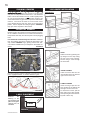
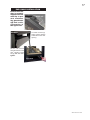
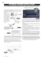
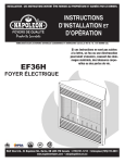
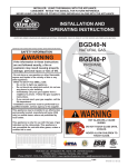
1
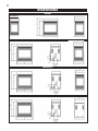
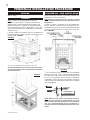
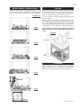
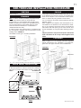
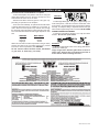
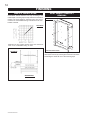
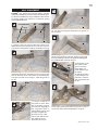
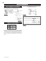
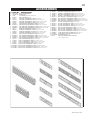
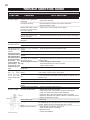
1
W415-0320 / D / 01.16.07
W415-0320 / D / 01.06.07
2
WARNINGS & SAFETY PRECAUTIONS
WHAT TO DO IF YOU SMELL GAS
W415-0320 / D / 01.06.07
3
TABLE of CONTENTS
Pg 2-6 INTRODUCTION
13
Warnings and Safety Precautions
Warranty
General Instructions
General Information
Care of Glass & Plated Parts
Dimensions
7
14-17 FINISHING
Mantle Height Locations
Heat shield stand-off removal
Log Placement/Charcoal Embers
Logo Placement
Door Opening and Closing
Upper Louvre Bracket and Hood
Lower Louvre Bracket and Hinge Screen
Louvre Installation
End Door Installation
VENTING
Vent Safety Switch
High Limit Switch
Venting Action
8-9
PENINSULA INSTALLATION PROCEDURE
Framing
Bar / Countertop Installation
Brick Panel Installation
Facing
10
OPTIONAL BLOWER INSTALLATION
19
OPERATION / MAINTENANCE
20
OPEN END INSTALLATION PROCEDURE
ADJUSTMENTS
Pilot Burner Adjustment
Venturi Adjustments
21-22 REPLACEMENTS
Ordering Replacement Parts
Replacement Parts
SEE-THRU INSTALLATION PROCEDURE
Framing
Brick Panel Installation
Facing
12
18
Operating Instructions
Maintenance
Framing
Brick Panel Installation
Facing
11
GAS SUPPLY CONNECTION
23
ISLAND INSTALLATION PROCEDURE
Framing
Brick Panel Installation
Facing
ACCESSORIES
24-25 TROUBLE SHOOTING GUIDE
26
SERVICE HISTORY
PLEASE RETAIN THIS MANUAL FOR FUTURE REFERENCE
WARNING
• Do not burn wood or other materials in this fireplace.
• Adults and especially children should be alerted to the hazards of high surface temperatures and should stay
away to avoid burns or clothing ignition. Supervise young children when they are in the same room as the
fireplace.
• Due to high temperatures, the fireplace should be located out of traffic and away from furniture and draperies.
• Clothing or other flammable material should not be placed on or near the fireplace.
• Any safety screen or guard removed for servicing must be replaced prior to operating the fireplace.
• It is imperative that the control compartments, burners and circulating blower and its passageway in the fireplace
and venting system are kept clean. The fireplace and its venting system should be inspected before use and at
least annually by a qualified service person. More frequent cleaning may be required due to excessive lint from
carpeting, bedding material, etc. The fireplace area must be kept clear and free from combustible materials,
gasoline and other flammable vapours and liquids.
• Under no circumstances should this fireplace be modified.
• This fireplace must not be connected to a chimney flue pipe serving a separate solid fuel burning appliance.
• Do not use this fireplace if any part has been under water. Immediately call a qualified service technician to inspect
the fireplace and to replace any part of the control system and any gas control which has been under water.
• Do not operate the fireplace with the glass door removed, cracked or broken. Replacement of the glass should be
done by a licensed or qualified service person.
• Do not strike or slam shut the fireplace glass door.
• This fireplace uses and requires a fast acting thermocouple. Replace only with a fast acting thermocouple supplied by Wolf Steel Ltd.
NOTE: changes, other than editorial, are denoted by a vertical line in the margin.
W415-0320 / D / 01.06.07
4
NAPOLEON gas fireplaces are manufactured under the strict Standard of the world recognized
ISO 9001 : 2000 Quality Assurance Certificate.
NAPOLEON products are designed with superior components and materials, assembled by trained craftsmen
who take great pride in their work. The burner and valve assembly are leak and test-fired at a quality test
station. The complete fireplace is thoroughly inspected by a qualified technician before packaging to ensure that
you, the customer, receives the quality product that you expect from NAPOLEON.
NAPOLEON GAS FIREPLACE PRESIDENT'S LIFETIME LIMITED WARRANTY
The following materials and workmanship in your new NAPOLEON gas fireplace are warranted against defects for as long as you own the fireplace. This covers: combustion chamber,
heat exchanger, stainless steel burner, phazer™ logs and embers, ceramic glass (thermal breakage
only), gold plated parts against tarnishing, porcelainized enamelled components and aluminum
extrusion trims.
Electrical (110V and millivolt) components and wearable parts such as blowers, gas valves,
thermal switch, switches, wiring, remote controls, ignitor, gasketing, and pilot assembly are
covered and NAPOLEON will provide replacement parts free of charge during the first year of
the limited warranty.
Labour related to warranty repair is covered free of charge during the first year. Repair work,
however, requires the prior approval of an authorized company official. Labour costs to the
account of NAPOLEON are based on a predetermined rate schedule and any repair work must
be done through an authorized NAPOLEON dealer.
CONDITIONS AND LIMITATIONS
NAPOLEON warrants its products against manufacturing defects to the original purchaser only -- i.e., the individual or legal entity (registered customer) whose name appears on the
warranty registration card filed with NAPOLEON -- provided that the purchase was made through an authorized NAPOLEON dealer and is subject to the following conditions and limitations:
This factory warranty is nontransferable and may not be extended whatsoever by any of our representatives.
The gas fireplace must be installed by a licenced, authorized service technician or contractor. Installation must be done in accordance with the installation instructions included with the
product and all local and national building and fire codes.
This limited warranty does not cover damages caused by misuse, lack of maintenance, accident, alterations, abuse or neglect and parts installed from other manufacturers will nullify
this warranty.
This limited warranty further does not cover any scratches, dents, corrosion or discolouring caused by excessive heat, abrasive and chemical cleaners nor chipping on porcelain enamel
parts, mechanical breakage of PHAZER™ logs and embers, nor any venting components used in the installation of the fireplace.
NAPOLEON warrants its stainless steel burners against defects in workmanship and material for life, subject to the following conditions: During the first 10 years NAPOLEON will replace
or repair the defective parts at our option free of charge. From 10 years to life, NAPOLEON will provide replacement burners at 50% of the current retail price.
In the first year only, this warranty extends to the repair or replacement of warranted parts which are defective in material or workmanship provided that the product has been operated
in accordance with the operation instructions and under normal conditions.
After the first year, with respect to this President's Limited Lifetime Warranty, NAPOLEON may, at its discretion, fully discharge all obligations with respect to this warranty by refunding
to the original warranted purchaser the wholesale price of any warranted but defective part(s).
After the first year, NAPOLEON will not be responsible for installation, labour or any other costs or expenses related to the reinstallation of a warranted part, and such expenses are not
covered by this warranty.
Notwithstanding any provisions contained in this President's Limited Lifetime Warranty, NAPOLEON’S responsibility under this warranty is defined as above and it shall not in any event
extend to any incidental, consequential or indirect damages.
This warranty defines the obligations and liability of NAPOLEON with respect to the NAPOLEON gas fireplace and any other warranties expressed or implied with respect to this product,
its components or accessories are excluded.
NAPOLEON neither assumes, nor authorizes any third party to assume, on its behalf, any other liabilities with respect to the sale of this product. NAPOLEON will not be responsible
for: over-firing, downdrafts, spillage caused by environmental conditions such as rooftops, buildings, nearby trees, hills, mountains, inadequate vents or ventilation, excessive venting
configurations, insufficient makeup air, or negative air pressures which may or may not be caused by mechanical systems such as exhaust fans, furnaces, clothes dryers, etc.
Any damages to fireplace, combustion chamber, heat exchanger, brass trim or other component due to water, weather damage, long periods of dampness, condensation, damaging
chemicals or cleaners will not be the responsibility of NAPOLEON.
The bill of sale or copy will be required together with a serial number and a model number when making any warranty claims from your authorized dealer. The warranty registration card
must be returned within fourteen days to register the warranty.
NAPOLEON reserves the right to have its representative inspect any product or part thereof prior to honouring any warranty claim.
ALL SPECIFICATIONS AND DESIGNS ARE SUBJECT TO CHANGE WITHOUT PRIOR NOTICE DUE TO ON-GOING PRODUCT IMPROVEMENTS. NAPOLEON® IS A REGISTERED
TRADEMARK OF WOLF STEEL LTD. PATENTS U.S. 5.303.693.801 - CAN. 2.073.411, 2.082.915. © WOLF STEEL LTD.
W415-0320 / D / 01.06.07
5
INTRODUCTION
GENERAL INSTRUCTIONS
GENERAL INFORMATION
THIS GAS FIREPLACE SHOULD BE INSTALLED AND
SERVICED BY A QUALIFIED INSTALLER to conform with
local codes. Installation practices vary from region to region and it is important to know the specifics that apply to
your area,
for example: in Massachusetts State:
FOR YOUR SATISFACTION, ALL BURNER ASSEMBLIES
HAVE BEEN TEST-FIRED TO ASSURE THEIR OPERATIONS AND QUALITY! Maximum input is 30,000 BTU/h
for natural gas and propane. When the fireplace is installed
at elevations above 4,500ft, and in the absence of specific
recommendations from the local authority having jurisdiction, the certified high altitude input rating shall be reduced
at the rate of 4% for each additional 1,000ft. Maximum output for natural gas is 20,400 BTU/hr at an efficiency of 68%
with the fan on.
Minimum inlet gas supply pressure is 4.5 inches water
column for natural gas and 11 inches water column for
propane. Maximum inlet gas pressure is 7 inches water
column for natural gas and 13 inches water column for
propane. Manifold pressure under flow conditions is 3.5
inches water column for natural gas and 10 inches water
column for propane.
This fireplace is approved for bedroom and bed-sitting room
installations and is suitable for mobile home installation.
• The fireplace damper must be removed or welded in the open
position prior to installation of a fireplace insert or gas log.
• The appliance off valve must be a “T” handle gas cock.
• The flexible connector must not be longer than 36 inches.
• The appliance is not approved for installation in a bedroom or
bathroom unless the unit is a direct vent sealed combustion
product.
• WARNING: This product must be installed by a licensed plumber
or gas fitter when installed within the commonwealth of
Massachusetts.
In absence of local codes, install to the current CAN/CGA B149 Installation Code in Canada or to the National Fuel
Gas Code, ANSI Z223.1, and NFPA 54 in the United States.
Mobile home installation must conform with local codes.
In the absence of local codes, install to the current standard for gas equipped mobile housing CAN/CSA Z240 MH
Series in Canada or the manufactured home construction
and safety standard, Title 24 CFR, part 3280, or the Fire
Safety Criteria for manufactured home installations, Sites
and Community Standard ANSI/NFPA 5OIA in the United
States.
Purge all gas lines with the glass door of the fireplace
open. Assure that a continuous gas flow is at the burner
before closing the door.
Under extreme vent configurations, allow several minutes (5-15) for the flame to stabilize after ignition.
The fireplace and its individual shutoff valve must be disconnected from the gas supply piping system during any
pressure testing of that system at test pressures in excess of 1/2 psig (3.5 kPa). The fireplace must be isolated
from the gas supply piping system by closing its individual
manual shutoff valve during any pressure testing of the
gas supply piping system at test pressures equal to or
less than 1/2 psig (3.5 kPa).
When the fireplace is installed directly on carpeting, vinyl
tile or other combustible material other than wood flooring,
the fireplace shall be installed on a metal or wood panel
extending the full width and depth.
If the optional heat circulating blower is installed, the blower
must be electrically connected and grounded in accordance with local codes. In the absence of local codes, use
the current CSA C22.1 CANADIAN ELECTRICAL CODE in
Canada or the ANSI/NFPA 70 NATIONAL ELECTRICAL
CODE in the United States.
Minimum clearance to combustible construction
from the fireplace:
sides, back, bottom, and top
0 inches
recessed depth (corner installation) 25 inches
Objects placed in front of the fireplace must be kept
a minimum of 48" away from the glass front faces of
the unit.
NO EXTERNAL ELECTRICITY (110 VOLTS OR 24 VOLTS) IS
REQUIRED FOR THE GAS SYSTEM OPERATION. Expansion / contraction noises during heating up and cooling
down cycles are normal and are to be expected.
If utilizing one of Wolf Steel's trim or surround kits, follow
the framing instructions on page 14 and the finishing instructions on page 23, for removal of the top extension.
CARE OF GLASS, AND PLATED PARTS
Do not use abrasive cleaners to clean these parts. Buff
lightly with a clean dry cloth. The glass is 3/16" tempered
glass available from your Napoleon / Wolf Steel Ltd. dealer.
Do not substitute materials.
If the door glass should crack or break, do not operate the
fireplace. Replace only with a door assembly certified with
the fireplace. See DOOR, LOUVRE AND TRIM INSTALLATION for removal and replacement details. Clean the glass
after the first 10 hours of operation with a recommended
gas fireplace glass cleaner. Thereafter clean as required.
Do not clean glass when hot!
If the glass is not kept clean permanent discolouration
and / or blemishes may result.
Provide adequate ventilation air. Provide adequate accessibility clearance for servicing and operating the fireplace. Never obstruct the front opening of the fireplace.
For safe and proper operation of the fireplace follow the
venting instruction exactly.
Provide a means for visually checking the vent connection to the fireplace after the fireplace is installed.
In order to avoid the possibility of exposed insulation
or vapour barrier coming in contact with the fireplace
body, it is recommended that the walls of the fireplace
enclosure be “finished” (ie: drywall/sheetrock), as you
would finish any other outside wall of a home. This will
ensure that clearance to combustibles is maintained
within the cavity.
W415-0320 / D / 01.06.07
6
DIMENSIONS
ISLAND
FIGURES 1a-d
OPEN-END
PENINSULA
SEE-THRU
W415-0320 / D / 01.06.07
7
VENTING
This is a vented appliance and must be connected to a
chimney in accordance with the current installation codes.
In absence of local codes, install to the current National
Fuel Gas Code, ANSI Z223.1, or the current CAN/CGA B149,
Installation Codes. This model can be common-vented.
A minimum five inch diameter (5"ø) B-vent or class A vent is
required. A minimum 5' vent height is required. Secure the
B-vent to the exhaust collar on the stove top with 3 screws.
In cold climates, the use of a B-vent and an insulated chase
is recommended.
VENTING SAFETY SWITCH
This thermally activated switch, located in front of the draft
hood, senses an increase in temperature and acts as a
safety shut-off (See 'A' below). It shuts down the gas to the
main burner in the event of a severe downdraft of air or a
blocked or disconnected chimney flue. If the flue is blocked
or has no "draw", the safety switch will automatically shut
off the supply of gas to the main burner within 10 minutes.
HIGH LIMIT SWITCH
This thermally activated switch, located in front of the draft
hood, senses an increase in temperature and acts as a
safety shut-off (See 'A' below). It shuts down the gas to the
main burner in the unlikely event of the unit overheating.
The HI Limit switch will automatically reset after the unit
has cooled down, resuming gas flow to the main burner.
VENT SAFETY
SWITCH
HIGH LIMIT
SWITCH
THERMOSTAT OR
WALL SWITCH
This switch must be manually reset by depressing
the plunger. Refer to Figure 2.
Tampering with the safety switch can result in carbon monoxide poisoning and possible death.
The one wire running from the vent safety switch is attached
to terminal 1 of the valve (See 'B' below). The other wire
(laying loose in the valve control area) may be attached to a
wall switch or thermostat.
FIGURE 3
VALVE
VENTING ACTION CHECK
A test for correct venting action must be made before
the installed unit can be left with the customer.
Follow the procedure below:
1.
Close all doors and windows in the room / start exhaust fans in the home / turn the fireplace blower off (if so
equipped).
2.
Set controls to "high" and light the unit.
3.
Wait 5 minutes. Light a match and hold to the front of
the draft hood. FIGURES 4 & 5.
HI LIMIT
SWITCH
PLUNGER
A
FIGURE 4
Venting action is satisfactory, if smoke and flames are
drawn into the draft hood.
FIGURE 5
B
Venting action is unsatisfactory, if the smoke spills back, and
the flame splays outward. If venting action is unsatisfactory,
turn off the unit, wait 10 minutes and try again. If the smoke is
still not drawn into the draft hood, turn the unit off and check for
vent blockage or restriction. If necessary, consult with a qualified inspector.
The Vent Safety or Hi Limit switches must not be
adjusted or disabled.
FIGURE 2
In the event that either switch or any associated
parts are exchanged, only original manufacturer's
parts may be used.
W415-0320 / D / 01.06.07
8
PENINSULA INSTALLATION PROCEDURE
VENTING
COUNTERTOP / BAR INSTALLATION
Refer to page 7.
FRAMING
Note: In order to avoid the possibility of exposed
insulation or vapour barrier coming in contact with the
fireplace body, it is recommended that the walls of the
fireplace enclosure be “finished” (ie: drywall/sheetrock),
as you would finish any other outside wall of a home. This
will ensure that clearance to combustibles is maintained
within the cavity.
It is best to frame your fireplace after it is positioned and
the vent system is installed. Use 2x4's and frame to local
building codes. FIGURE 6.
When finishing the fireplace, combustible material may
rest directly on of the top extension.
Note: Maximum weight tolerance is 400 lbs, provided
that it is evenly distributed across the top extensions of
the fireplace.
In order to achieve a countertop or bar type appearance
with the minimum height allowed, framing must be noncombustible and may be done with metal studding attached
to the top extension sides or the upper frame of the fireplace. FIGURE 9.
FIGURE 6
A = 22 " minus finishing material thickness each side.
To install the fireplace face flush with the finished wall,
position the framework to accommodate the thickness
of the finished wall.
FIGURE 7
FIGURE 8
*
The top extension may be removed if non-combustible
framing is faced with a non-combustible material placed
flush with the front face of the unit and extending from the
top of the unit. (Example: cement board) (not supplied).
Combustible counter / bar tops must maintain a minimum
of 38½ inches from the base of the fireplace to the underside
of the top. Figure 7.
FIGURE 9
TOP EXTENTION
TOP OF THE UNIT
NOTE: Wolf Steel trim and/or surround kits will not totally cover the top extension of the fireplace. In order to
obtain a smooth transition from the trim / surround to the
wall, it is recommended that the top extension be removed and the unit be installed following the above procedure.
W415-0320 / D / 01.06.07
9
BRICK PANEL INSTALLATION
FACING
Install the base panels as illustrated in steps 1-4 . The
side panel sits under the bracket tab. Holding the side
panel in position, bend down the tab to secure. DETAIL 5.
Combustible materials may be installed flush with the front
of the fireplace but must not cover any of the black faceareas of the fireplace. Non-combustible material (brick,
stone or ceramic tile) may protrude in these areas.
It is not necessary to install a hearth extension with this
fireplace system.
When roughing in the fireplace, raise the fireplace to accommodate for the thickness of the finished floor materials, i.e. tile, carpeting, hard wood, which if not planned for
will interfere with the opening of the lower access door and
the installation of many decorative flashing accessories.
FIGURES 10a-e
STEP 1
Objects placed in front of the fireplace should be
kept a minimum of 48" away from the glass front
faces.
FIGURE 11
DRYWALL
DRYWALL
STEP 2
4" MIN
STEP 3
FINISHING
Refer to pages 14-17 for complete instructions regarding
mantle requirements and installations, log placement,
glass door and upper and lower louvre attachments.
STEP 4
RETAINER
STEP 5
DETAIL5
W415-0320 / D / 01.06.07
10
OPEN-END INSTALLATION PROCEDURE
VENTING
FIGURES 13a-c
Refer to page 7.
FRAMING
Note: In order to avoid the possibility of exposed insulation or vapour barrier coming in contact with the
fireplace body, it is recommended that the walls of the
fireplace enclosure be “finished” (ie: drywall/sheetrock),
as you would finish any other outside wall of a home. This
will ensure that clearance to combustibles is maintained
within the cavity.
It is best to frame your fireplace after it is positioned and
the vent system is installed. Use 2x4's and frame to local
building codes. FIGURE 12.
STEP 5
RETAINER
FIGURE 12
DETAIL 6
STEP 6
FACING
Combustible materials may be installed flush with the front
of the fireplace but must not cover any of the black faceareas of the fireplace. Non-combustible material (brick,
stone or ceramic tile) may protrude in these areas.
It is not necessary to install a hearth extension with this
fireplace system.
When roughing in the fireplace, raise the fireplace to accommodate for the thickness of the finished floor materials, i.e. tile, carpeting, hard wood, which if not planned for
will interfere with the opening of the lower access door and
the installation of many decorative flashing accessories.
A = 251/4" minus finishing material thickness each side.
NOTE: LEFT CORNER UNIT ILLUSTRATED
To install the fireplace face flush with the finished wall,
position the framework to accommodate the thickness
of the finished wall.
BRICK PANEL INSTALLATION
Install the base panels as illustrated in steps 1-4 on page
9. The side panel sits under the bracket tab. Holding the
side panel in position, bend down the tab to secure. DETAIL 6.
Objects placed in front of the fireplace should be
kept a minimum of 48" away from the glass front
faces.
FINISHING
Refer to pages 14-17 for complete instructions regarding
mantle requirements and installations, log placement,
glass door and upper and lower louvre attachments.
FIGURE 14
DRYWALL
DRYWALL
4" MIN
W415-0320 / D / 01.06.07
11
SEE-THROUGH INSTALLATION PROCEDURE
VENTING
FACING
Refer to page 7.
FRAMING
Note: In order to avoid the possibility of exposed insulation or vapour barrier coming in contact with the
fireplace body, it is recommended that the walls of the
fireplace enclosure be “finished” (ie: drywall/sheetrock),
as you would finish any other outside wall of a home.
This will ensure that clearance to combustibles is
maintained within the cavity.
It is best to frame your fireplace after it is positioned and
the vent system is installed. Use 2x4's and frame to local
building codes. FIGURE 15.
See PAGE 7 for bar type / countertop installation.
FIGURE 15
Combustible materials may be installed flush with the front
of the fireplace but must not cover any of the black faceareas of the fireplace. Non-combustible material (brick,
stone or ceramic tile) may protrude in these areas.
It is not necessary to install a hearth extension with this
fireplace system.
When roughing in the fireplace, raise the fireplace to accommodate for the thickness of the finished floor materials, i.e. tile, carpeting, hard wood, which if not planned for
will interfere with the opening of the lower access door
and the installation of many decorative flashing accessories.
Objects placed in front of the fireplace should be
kept a minimum of 48" away from the glass front
faces.
FINISHING
Refer to pages 14-17 for complete instructions regarding
mantle requirements and installations, log placement,
glass door and upper and lower louvre attachments.
FIGURE 17
DRYWALL
DRYWALL
A = 221/8" minus finishing material thickness, each side.
BRICK PANEL INSTALLATION
Install the base panels as illustrated in steps 1-4 on page
9. Both side panels sit under the bracket tab. Holding the
side panel in position, bend down the tab to secure. DETAIL 6.
FIGURES 16a-c
4" MIN
RETAINER
STEP 5
DETAIL 5 & 6
RETAINER
STEP 6
W415-0320 / D / 01.06.07
12
ISLAND INSTALLATION PROCEDURE
FRAMING
BRICK PANEL INSTALLATION
It is best to frame your fireplace after it is positioned. Use
2x4's and frame to local building codes. FIGURE 18.
Install the base panels as illustrated in steps 1-4 on page
9.
FACING
FIGURE 18
Combustible materials may be installed flush with the front
of the fireplace but must not cover any of the black faceareas of the fireplace. Non-combustible material (brick,
stone or ceramic tile) may protrude in these areas.
It is not necessary to install a hearth extension with this
fireplace system.
When roughing in the fireplace, raise the fireplace to accommodate for the thickness of the finished floor materials, i.e. tile, carpeting, hard wood, which if not planned for
will interfere with the opening of the lower access door and
the installation of many decorative flashing accessories.
Objects placed in front of the fireplace should be
kept a minimum of 48" away from the glass front
faces.
A = 221/8 " minus finishing material thickness each side.
B = 36 " minus finishing material thickness each end.
FIGURE 20
To install the fireplace face flush with the finished wall,
position the framework to accommodate the thickness
of the finished wall.
FIGURE 19
DRYWALL
DRYWALL
FINISHING
Refer to pages 14-17 for complete instructions regarding
mantle requirements and installations, log placement,
glass door and upper and lower louvre attachments.
W415-0320 / D / 01.06.07
13
GAS INSTALLATION
1
2
O
LO
ON
PL T
IH
O I
3
PI L OT
Do not connect either the wall switch, thermostat
or gas valve to electricity (110 volts).
FIGURE 21
FF
Proceed once the vent installation is complete.
1. Move the fireplace into position and secure using the
nailing tabs and/or secure to the floor through the 1/4"ø
holes located at either end of the base.
2. Route a 3/8" N.P.T. black iron gas line, 1/2" type-L copper tubing or equivalent to the fireplace.
3. For ease of accessibility, an optional remote wall switch
or millivolt thermostat may be installed in a convenient location. Route 2-strand (solid core) millivolt wire through
the electrical hole located at the bottom left side of the unit.
The recommended maximum lead length depends on wire
size:
WIRE SIZE
MAX. LENGTH
14gauge
100 feet
16gauge
60 feet
18gauge
40 feet
Attach the one lead to terminal 3 (located on the gas valve)
and the other lead to the vent safety switch wire ( located
loose in the valve compartment). See FIGURE 3.
4. Install rigid black pipe, 1/2" type-L copper tubing or, if
local codes permit, a 3/8" flex connector and shutoff valve
to the gas line and the fireplace gas valve. Seal and tighten
securely. An adapter fitting is required between the gas
valve and the copper tubing or flex connector. DO NOT KINK
FLEXIBLE CONNECTOR. FIGURE 6.
5. Check for gas leaks by brushing on a soap and water
solution. Do not use open flame.
FIGURE 22
6. Mark the appropriate boxes on the rating plate label to
indicate the model type.
Purge all gas lines with the glass door of the fireplace open. Assure that a continuous gas flow is
at the burner before closing the door.
FIGURE 23
W415-0320 / D / 01.06.07
14
FINISHING
MANTLE INSTALLATION
Combustible mantle clearance can vary according to the
mantle depth. Use the graph to help evaluate the clearance
needed. The three-sided top extension piece may be removed if non-combustible framing is faced with a non-combustible material.
HEAT SHIELD STAND-OFF
REMOVAL
FIGURE 26
HE
AT
S
HIE
FIGURE 24
Dashed lines are suitable mantle sizes and clearances
when a non-combustible facing is used.
STA
ND
LD
-OF
FS
END HEAT SHIELD SHOWN
FIGURE 25
When using a non-combustible finishing material, the standoffs may be removed, by removing the set screw in the centre
and sliding the stand-offs out of the mounting clips.
* SEE FIGURE 9.
W415-0320 / D / 01.06.07
15
LOG PLACEMENT
E
TM
PHAZER logs, glowing and charcoal embers, exclusive
to Napoleon fireplaces, provide a unique and realistic glowing effect that is different in every installation. Take the time
to carefully position the embers for a maximum glowing
effect. Figures 27 A - H.
A
#1
LOCATING PINS
#3
LOCATING PINS
PILOT
5. When pieces #3a and #3b are attached to create log
#3, the upper end of log #3 should rest in the groove, on
top of log # 2.
F
1. Looking at the unit from the valve side, place log #1
diagonally across the textured burner cover onto the pins.
The texture is designed to cradle the underside of the log.
B
#4
#2
6. As with log # 1, log #4 is also cradled by the texture of the
burner cover and the pin in the base. Position log #4 so that
the lower end fits onto the pin. The upper end rests against
the moulded locater on the top of log # 1.
G
#5
b
2. Depending on the type of installation, the view of the log
positioning will reverse. Here the lower end of log #2 rests
near the back left corner of the firebox on the locating pin.
The upper end sits on top of log #1, inside the groove on
log #2.
C
7. Like log #3, log #5
also comes in two
pieces. The base
(#5a) slopes outwards between logs
#2 and #4.
As with pieces #3a &
b, piece #5b fits over
piece #5a. Place the
end of piece #5b onto
the pin.
a
#3a
H
#2
#5
#3
D
#3
b
a
3. Log # 3 is made up of
two pieces, a and b. Piece
#3a is the base of log #3.
The base sits diagonally in
the designated area located between logs #1 and
fits tight up against #2.
#1
#4
8. The upper end of log #5 rests in the groove, on top of
log #4 and creates the final appearance of log set.
4. The slot in the underside of piece #3b fits over
#3a. Place the end of
piece #3b onto the pin.
W415-0320 / D / 01.06.07
16
GLOWING EMBERS
L36 LOUVRE INSTALLATION
For proper ignition, it is very important to that glowing
ember
s ar
e in place
embers
are
place.. Tear the embers into small pieces
and place on the ported area of the burner. Care should be
taken to shred the embers into thin, small irregular pieces
as only the exposed edges of the fibre hairs will glow. The
ember material will only glow when exposed to direct flame;
however, care should be taken to not block the burner
ports. Blocked burner ports can cause an incorrect flame
pattern, carbon deposits and delayed ignition. PHAZERTM
logs glow when exposed to direct flame.
FIGURE 36 a-c
A
B
CHARCOAL EMBERS
Randomly place the embers around the bottom brick panels in a realistic manner but not in contact with the flames.
Keep ember dust away from burner ports to avoid plugging
them.
C
Fine dust found in bottom of bag not to be used. PHAZERTM
logs, and embers glow when exposed to direct flame. Use
only certified PHAZERTM logs, glowing embers and charcoal embers available from your Napoleon / Wolf Steel Ltd.
dealer.
FIGURE 28
A
CLIPS
GLOWING EMBERS
FLANGE
CENTRE
HOOD
Attach the hood by pressing the
top flange into the clips along
the top of the louvre opening.
Secure using a screw through
the centre slot.
SLOT
Ensure that glowing embers sufficiently cover the carry over
ports, highlighted below, to achieve maximum glow.
SLOT
CARRY OVER PORTS
UPPER LOUVRES
Insert the louvre tabs into the
slots located at the top left and
right corners of the unit.
TA B
B
C
HINGE
CLIP
FIGURE 29
LOGO PLACEMENT
Remove
the
backing of the
logo supplied and
place on the glass
viewing door, as
indicated.
½"
LOGO
½"
FIGURE 30
W415-0320 / D / 01.06.07
SLOT
LOWER LOUVRES
Insert the hinge clips into the
slots located at the bottom left
and right corners of the unit.
To remove the louvres, pull the
back tabs of the clips forward,
while pushing the louvre assembly back. Lift the clip.
17
END DOOR INSTALLATION
Ensure that the
door is properly
clipped onto the
steel lip to prevent overheating, glass breakage and / or discolouration of
the upper trim.
FIGURE 38
FIGURE 37
STEEL LIP
DOOR
To install the door(s),
hook it over the steel lip
located above the door
opening.
Secure with screws
along the bottom of the
door. Tighten screws
snugly. Do not overtighten.
FIGURE 39
W415-0320 / D / 01.06.07
18
OPTIONAL BLOWER INSTALLATION
THIS BLOWER IS NOT SUITABLE FOR THE 4 SIDED ISLAND INSTALLATION.
THERMODISC WIRES TO BLOWER
in accordance with local codes. In the absence of local
codes, use the current CSA C22.1 CANADIAN ELECTRICAL CODE
in Canada or the ANSI/NFPA 70 NATIONAL ELECTRICAL CODE in the
United States.
Remove
the
blower from its
mounting bracket
and attach to the
bracket supplied
with the fireplace.
FIGURE 40
This bracket is
found secured on
the mounting stud
located at the bottom of the vent
side wall.
FIGURE 41
FIGURE 42
The blower bracket contains two holes that allow the blower
to be positioned away from the intended gas supply hole.
Position the vibration reducing pad, centred, onto the
threaded stud, piercing a hole into the pad. The blower
must be able to be positioned entirely onto the pad.
Tilt the blower onto its side and slide it past the controls.
Position the blower under the clip and onto the stud. Secure with a wing nut.
FIGURE 43
W415-0320 / D / 01.06.07
THERMODISC BRACKET
FIGURE 44
Remove the thermodisc bracket from the top of the firebox.
Remove the thermodisc from the bracket supplied in the
blower kit and install the thermodisc into the fireplace
bracket. Then replace the bracket in the location it was
removed.
Connect the two ends of the unattached wires by the bracket
to the thermodisc.
Connect the opposite ends of the wires to the red and
black leads of the blower harness.
The wire harness provided in this kit is a universal harness. When installed, ensure that any excess wire is
contained, preventing it from making contact with moving or hot objects.
Drywall dust will penetrate into the blower bearings,
causing irreparable damage. Care must be taken to
prevent drywall dust from coming into contact with the
blower or its compartment. Any damage resulting from
this condition is not covered by the warranty policy.
Because the blower is thermally activated, when turned
on, it will automatically start approximately 10 minutes
after lighting the fireplace and will run for approximately
30 - 45 minutes after the fireplace has been turned off.
Use of the fan increases the output of heat.
19
OPERATION / MAINTENANCE
FOR YOUR SAFETY READ BEFORE LIGHTING:
WHAT TO DO IF YOU SMELL GAS:
Purge the gas line with a glass door open. Assure that
a continuous gas flow is at the burner before re-installing the door.
A. This fireplace is equipped with a pilot which must be lit by
hand while following these instructions exactly.
B. Before operating smell all around the fireplace area for
gas and next to the floor because some gas is heavier
than air and will settle on the floor.
C. Use only your hand to turn the gas control knob. Never use
tools. If the knob will not turn by hand, do not try to repair it.
Call a qualified service technician. Force or attempted repair may result in a fire or explosion.
D. Do not use this fireplace if any part has been under water.
Immediately call a qualified service technician to inspect
the fireplace and replace any part of the control system and
any gas control which has been under water.
• Turn off all gas to the fireplace.
• Open windows.
• Do not try to light any appliance.
• Do not touch any electric switch; do
not use any phone in your building.
• Immediately call your gas supplier from
a neighbour's phone. Follow the gas
supplier's instructions.
• If you cannot reach your gas supplier, call
the fire department.
WARNING: The gas valve has an interlock GAS KNOB
device which will not allow the pilot burner to be lit until the
thermocouple has cooled. Allow approximately 60 seconds
for the thermocouple to cool.
When lighting and re-lighting, the gas knob cannot be
turned from pilot to off unless the knob is depressed
slightly.
LIGHTING INSTRUCTIONS
1.
2.
3.
4.
Stop! Read the above safety information on this label.
Turn off all electric power to the fireplace.
Turn the gas knob clockwise to off.
Wait five (5) minutes to clear out any gas. If you smell
gas including near the floor. Stop! Follow "B" in the above
safety information on this label. If you don't smell gas go
the next step.
5. Turn gas knob counter-clockwise to pilot.
6. Depress slightly and hold gas knob while lighting the
pilot with the push button ignitor. Keep knob depressed
for one minute, then release. If pilot does not continue to
burn, repeat steps 3 through 5.
7. With pilot lit, depress and turn gas knob counter-clockwise to on.
8. If equipped with remote on-off switch/thermostat, main
burner may not come on when you turn valve to on.
Remote switch must be in the on position to ignite
burner.
9. Turn on all electric power to the fireplace.
TO TURN OFF GAS
1. Turn off all electric power to the fireplace if service is to be
performed.
2. For a complete shut-down procedure: push in gas control
knob slightly and turn clockwise to off. Do not force.
3. For a temporary shut-down procedure: set thermostat to
lowest setting or remote switch to off. Press and turn the
gas knob clockwise to pilot.
Turn off the gas and electrical power before servicing the
fireplace.
MAINTENANCE
CAUTION: Label all wires prior to disconnection when servicing controls. Wiring errors can cause improper and dangerous operation. Verify proper operation after servicing. This fireplace and its venting system should be inspected before use
and at least annually by a qualified service person. The fireplace area must be kept clear and free of combustible materials, gasoline or other flammable vapours and liquids. The flow
of combustion and ventilation air must not be obstructed.
1. In order to properly clean the burner and pilot assembly,
remove the logs to expose both assemblies.
2. Keep the control compartment, logs, burner, air shutter opening and the area surrounding the logs clean by vacuuming or
brushing, at least once a year.
3. Check to see that all burner ports are burning. Clean out any
of the ports which may not be burning or are not burning properly.
4. Check to see that the pilot flame is large enough to engulf
the thermocouple and thermopile and reaches toward the
burner with the third jet.
5. Replace the cleaned logs.
6. Check to see that the main and runner burners ignite completely on all openings when the gas knob for the burners is
turned on. A 5 to 10 second total light-up period is satisfactory. If
ignition takes longer, consult your Napoleon dealer / distributor.
7. Check that the gasketing on the sides, top and bottom
of the door is not broken or missing. Replace if necessary.
W415-0320 / D / 01.06.07
20
ADJUSTMENTS
PILOT BURNER ADJUSTMENT
AIR SHUTTER ADJUSTMENT MUST ONLY BE DONE BY A
QUALIFIED GAS INSTALLER!
Adjust the pilot screw to provide properly sized flame. Turn
in a clockwise direction to reduce the gas flow.
FIGURE 47
FIGURE 45
VENTURI
FIGURE 46
VENTURI ADJUSTMENT
MODEL BGNV40
NG
1/4"
LP
7/16"
Closing the air shutter will cause a more yellow flame, but
can lead to carboning. Opening the air shutter will cause a
more blue flame, but can cause flame lifting from the burner
ports. The flame may not appear yellow immediately; allow 15 to 30 minutes for the final flame colour to be established.
W415-0320 / D / 01.06.07
FIGURE 48
21
REPLACEMENTS
Contact your dealer for questions concerning prices and
availability of replacement parts. Normally all parts can be
ordered through your Napoleon dealer or distributor.
* IDENTIFIES ITEMS WHICH ARE NOT ILLUSTRATED. FOR
FURTHER INFORMATION, CONTACT YOUR NAPOLEON
DEALER.
When ordering replacement parts always give the following information:
1. MODEL & SERIAL NUMBER OF FIREPLACE
2. INSTALLATION DATE OF FIREPLACE
3. PART NUMBER
4. DESCRIPTION OF PART
5. FINISH
6. TOP OR REAR VENT
COMPONENTS COMMON TO ALL UNITS
#
PART No.
DESCRIPTION
1*
2*
3
4
5
6*
7
8
9
10
11
12
13
14
15
16
17
18
19
20
W361-0016
W550-0001
W010-0516
W562-0009
W010-0454
W385-0245
GL-634
W135-0153
W135-0154
W135-0155
W135-0156
W135-0157
W135-0158
W135-0159
W475-0511
W475-0512
W475-0515
W475-0513
W080-0519
W565-0041
GLOWING EMBERS
CHARCOAL EMBERS
BLACK SIDE DOOR c/w GLASS
DOOR GASKET (100 INCHES)
GLASS W/ GASKET
NAPOLEON LOGO
BGNV40 LOGSET
LOG#1
LOG#2
LOG#3 - PIECE A
LOG#3 - PIECE B
LOG#4
LOG#5 - PIECE A
LOG#5 - PIECE B
END FIBRE BRICK PANEL - FOR BURNER
END FIBRE BRICK PANEL - FOR BURNER
SIDE FIBRE BRICK PANEL - FOR BURNER
SIDE FIBRE BRICK PANEL - FOR BURNER
BOTTOM LOUVRE BRACKET
SIDE HINGE SCREEN
BURNER COMPONENTS
32
33
W010-0871
W010-0801
REPLACEMENT BURNER
NATURAL GAS PILOT ASSEMBLY
33
W010-0800
PROPANE GAS PILOT ASSEMBLY
34
34
W455-0069
W455-0067
NATURAL GAS PILOT INJECTOR
PROPANE GAS PILOT INJECTOR
35*
36
37
38
39
40
W660-0005
W680-0004
W680-0005
W240-0006
W357-0001
N455-0003
BURNER ON/OFF SWITCH
THERMOPILE
THERMOCOUPLE
ELECTRODE W / WIRE
PIEZO IGNITER
MAIN BURNER ORIFICE - PROPANE
COMPONENTS UNIQUE TO OPEN END UNIT
21
22
23
24
25
26
27
28
29
30
31
W475-0516
W500-0193
W200-0114
N010-0327
W300-0057
W475-0517
W010-0873
W500-0192
W565-0054
W585-0126
N010-0323
END FIBRE BRICK PANEL - FOR WALL
BRICK PANEL RETAINER
SIDE DOOR COVER
SIDE DOOR HEAT SHIELD
END DOOR TEMPERED GLASS ONLY
SIDE BRICK PANEL - FOR WALL
BLACK END DOOR c/w GLASS
END BRICK PANEL RETAINER
END HINGE SCREEN
END DOOR HEAT SHIELD
END DOOR COVER
COMPONENTS UNIQUE TO SEE-THRU UNIT
21
28
30
31
21
27
28
29
30
31
27
29
W475-0516
W500-0192
W585-0126
N010-0323
END
END
END
END
FIBRE BRICK PANEL - FOR
BRICK PANEL RETAINER
DOOR HEAT SHIELD
DOOR COVER
WALL
W475-0516
W010-0873
W500-0192
W565-0054
W585-0126
N010-0323
END FIBRE BRICK PANEL - FOR
BLACK END DOOR c/w GLASS
END BRICK PANEL RETAINER
END HINGE SCREEN
END DOOR HEAT SHIELD
END DOOR COVER
WALL
W010-0873
W565-0054
BLACK END DOOR c/w GLASS
END HINGE SCREEN
COMPONENTS UNIQUE TO PENINSULA UNIT
COMPONENTS UNIQUE TO ISLAND UNIT
W415-0320 / D / 01.06.07
22
W415-0320 / D / 01.06.07
* WARNING: This is a fast acting thermocouple. It is an integral safety component.
Replace only with a fast acting thermocouple supplied by Wolf Steel Ltd.
23
ACCESSORIES
# PART No.
1*
2*
3
4
5
5
5
5
6
6
6
6
7
7
7
7
8
8
8
8
9
9
9
9
10
10
10
10
W690-0001
GZ-550-1KT
L36K
ELB40K
HOIG-1
HOIKG-1
HOIBC-1
HOIBG -1
EHOIG-1
EHOIKG-1
EHOIBC-1
EHOIBG-1
DOIG-1
DOIKG-1
DOIBC-1
DOIBG-1
EDOIG-1
EDOIKG-1
EDOIBC-1
EDOIBG-1
GOIG-1
GOIKG-1
GOIBC-1
GOIBG-1
EGOIG-1
EGOIKG-1
EGOIBC-1
EGOIBG-1
DESCRIPTION
MILLIVOLT THERMOSTAT
BLOWER KIT
LOUVRE KIT-UPPER & LOWER -BLACK
END LOUVRE KIT-BLACK
HERITAGE ORNAMENTAL INSET-GOLD PLATED
HERITAGE ORNAMENTAL INSET-BLACK GOLD PLATED
HERITAGE ORNAMENTAL INSET-BRUSHED COPPER PLATED
HERITAGE ORNAMENTAL INSET-BRUSHED GOLD PLATED
END HERITAGE ORNAMENTAL INSET-GOLD PLATED
END HERITAGE ORNAMENTAL INSET-BLACK GOLD PLATED
END HERITAGE ORNAMENTAL INSET-BRUSHED COPPER PLATED
END HERITAGE ORNAMENTAL INSET-BRUSHED GOLD PLATED
DIAMOND ORNAMENTAL INSET-GOLD PLATED
DIAMOND ORNAMENTAL INSET-BLACK GOLD PLATED
DIAMOND ORNAMENTAL INSET-BRUSHED COPPER PLATED
DIAMOND ORNAMENTAL INSET-BRUSHED GOLD PLATED
END DIAMOND ORNAMENTAL INSET-GOLD PLATED
END DIAMOND ORNAMENTAL INSET-BLACK GOLD PLATED
END DIAMOND ORNAMENTAL INSET-BRUSHED COPPER PLATED
END DIAMOND ORNAMENTAL INSET-BRUSHED GOLD PLATED
GOTHIC ORNAMENTAL INSET- GOLD PLATED
GOTHIC ORNAMENTAL INSET-BLACK GOLD PLATED
GOTHIC ORNAMENTAL INSET- BRUSHED COPPER PLATED
GOTHIC ORNAMENTAL INSET-BRUSHED GOLD PLATED
END GOTHIC ORNAMENTAL INSET-GOLD PLATED
END GOTHIC ORNAMENTAL INSET-BLACK GOLD PLATED
END GOTHIC ORNAMENTAL INSET-BRUSHED COPPER PLATED
END GOTHIC ORNAMENTAL INSET-BRUSHED GOLD PLATED
11
11
11
11
12
12
12
12
13
13
13
13
14
14
14
14
15*
15*
16*
17*
SOIG-1
SOIKG-1
SOIBC-1
SOIBG-1
ESOIG-1
ESOIKG-1
ESOIBC-1
ESOIBG-1
EOIG-1
EOIKG-1
EOIBC-1
EOIBG-1
EEOIG-1
EEOIKG-1
EEOIBC-1
EEOIBG-1
GD825N
GD825P
W175-0205
FC-12
SEASHELL ORNAMENTAL INSET-GOLD PLATED
SEASHELL ORNAMENTAL INSET-BLACK GOLD PLATED
SEASHEL ORNAMENTAL INSET- BRUSHED COPPER PLATED
SEASHELL ORNAMENTAL INSET-BRUSHED GOLD PLATED
END SEASHELL ORNAMENTAL INSET-GOLD PLATED
END SEASHELL ORNAMENTAL INSET-BLACK GOLD PLATED
END SEASHELL ORNAMENTAL INSET- BRUSHED COPPER PLATED
END SEASHELL ORNAMENTAL INSET-BRUSHED GOLD PLATED
ECLIPSE ORNAMENTAL INSET-GOLD PLATED
ECLIPSE ORNAMENTAL INSET-BLACK GOLD PLATED
ECLIPSE ORNAMENTAL INSET- BRUSHED COPPER PLATED
ECLIPSE ORNAMENTAL INSET-BRUSHED GOLD PLATED
END ECLIPSE ORNAMENTAL INSET-GOLD PLATED
END ECLIPSE ORNAMENTAL INSET-BLACK GOLD PLATED
END ECLIPSE ORNAMENTAL INSET-BRUSHED COPPER PLATED
END ECLIPSE ORNAMENTAL INSET-BRUSHED GOLD PLATED
VALVE REGULATOR FOR W660-0013-NATURAL GAS
VALVE REGULATOR FOR W660-0013-PROPANE
CONVERSION KIT-NG-LP
GAS FLEX CONNECTOR & SHUT OFF
- 12" STAINLESS STEEL
W415-0320 / D / 01.06.07
24
TROUBLE SHOOTING GUIDE
BEFORE
ATTEMPTING TO TROUBLESHOOT, PURGE YOUR UNIT AND INITIALLY LIGHT THE PILOT AND THE MAIN BURNER WITH THE GLASS DOOR OPEN.
SYMPTOM
PROBLEM
TEST SOLUTION
Main burner goes Pilot flame is not large - turn up pilot flame.
out; pilot stays on. enough or not engulfing the - replace pilot assembly.
thermopile
Thermopile shorting
- clean thermopile connection to the valve. Reconnect.
- replace thermopile / valve.
Remote wall switch wire is - shorten wire to correct length or wire gauge.
too long; too much resistance in the system.
Faulty thermostat or switch. - replace.
Vent safety switch has
opened. (Tripped)
Hi Limit switch has opened.
(Tripped)
- Vent has become blocked or disconnected. Correct. See Figure 2.
- Unit has overheated. See Figure 2
Main burner goes Refer to "MAIN BURNER GOES OUT; PILOT STAYS ON"
out; pilot goes out.
Faulty thermocouple.
- replace.
Pilot goes out when
the gas knob is released.
The gas valve has
an interlock device
which will not allow
the pilot burner to
be lit until the thermocouple
has
cooled. Allow approximately 60
seconds for the
thermocouple to
cool.
System is not correctly - purge the gas line with the glass door open.
purged.
Pilot burning; no
gas
to
main
burner; gas knob
is on 'HI'; wall
switch / thermostat
is on.
Out of propane gas.
- fill the tank.
Pilot flame is not large - turn up the pilot flame.
enough
Pilot flame is not engulfing
the thermocouple.
Thermocouple shorting /
faulty.
- gently twist the pilot head to improve the flame pattern around the
thermocouple.
- loosen and tighten thermocouple.
- clean thermocouple and valve connection.
- replace thermocouple.
Faulty valve.
- replace.
Themostat or switch is defective.
Wall switch wiring is defective.
- connect a jumper wire across the wall switch terminals; if main
burner lights, replace switch / thermostat.
- disconnect switch wires & connect a jumper wire across terminals
1 & 3; if the main burner lights, check the wires for defects and / or
replace wires.
- remove stoppage in orifice.
Main burner orifice is plugged.
- replace.
Faulty valve.
Vent safety switch has opened. - Vent has become blocked or disconnected. Correct. See Figure 2.
(Tripped)
Hi Limit switch has opened. (Tripped) - Unit has overheated. See Figure 2
Pilot will not light.
No spark at pilot burner
Out of propane gas
Spark gap is incorrect
No gas at the pilot burner
W415-0320 / D / 01.06.07
- check if pilot can be lit by a match
- check that the wire is connected to the push button ignitor.
- check if the push button ignitor needs tightening.
- replace the wire if the wire insulation is broken or frayed.
- replace the electrode if the ceramic insulator is cracked or broken.
- replace the push button ignitor.
- fill the tank.
- spark gap should be 0.150" to 0.175" (5/32" to 11/64" approx.) from
the electrode tip and the pilot burner. To ensure proper electrode
location, tighten securing nut (finger tight plus 1/4 turn).
- check that the manual valve is turned on.
- check the pilot orifice for blockage.
- replace the valve.
- call the gas distributor.
25
SYMPTOM
PROBLEM
Pilot goes out Gas piping is undersized.
while standing;
Main burner is in
'OFF' position.
TEST SOLUTION
- turn on all gas appliances and see if pilot flame flutters, diminishes or extinguishes, especially when main burner ignites. Monitor
appliance supply working pressure.
- check if supply piping size is to code. Correct all undersized piping.
Flames are con- Unit is over-fired or under- - check pressure readings:
sistently too large fired.
Inlet pressure can be checked by turning screw (A) counter-clockor too small.
wise 2 or 3 turns and then placing pressure gauge tubing over the
Carboning occurs.
test point. Gauge should read 7" (minimum 4.5") water column for
natural gas or 13" (11" minimum) water column for propane. Check
that main burner is operating on "HI".
Outlet pressure can be checked the same as above using screw
(B). Gauge should read 3.5" water column for natural gas or 10"
water column for propane. Check that main burner is operating on
"HI".
AFTER TAKING PRESSURE READINGS, BE SURE TO TURN
SCREWS CLOCKWISE FIRMLY TO RESEAL. DO NOT OVERTORQUE.
Leak test with a soap and water solution.
Carbon is being
deposited
on
glass, logs or combustion chamber
surfaces.
Air shutter has become
blocked
- ensure air shutter opening is free of lint or other obstructions.
Flame is impinging on the
logs or combustion chamber.
- check that the logs are correctly positioned.
- open air shutter to increase the primary air.
- check the input rate: check the manifold pressure and orifice size
as specified by the rating plate values.
- check to ensure proper venting action
White / grey film Sulphur from fuel is being
forms.
deposited on glass, logs or
combustion chamber surfaces.
- clean the glass with a recommended gas fireplace glass cleaner.
DO NOT CLEAN GLASS WHEN HOT.
If deposits are not cleaned off regularly, the glass may become
permanently marked.
Exhaust fumes Fireplace is spilling.
smelled in room,
headaches.
- check for chimney blockage
- check that chimney is installed to building code.
- room is in negative pressure; increase fresh air supply.
Main burner flame Not enough combustion air
is a blue, lazy,
transparent flame.
- room is in negative pressure; increase fresh air supply
Remote
wall
switch is in "OFF"
position;
main
burner comes on
when gas knob is
turned to "ON" position.
Wall switch is mounted up- - reverse.
side down
Remote wall switch is - replace.
grounding.
Remote wall switch wire is - check for ground (short); repair ground or replace wire.
grounding.
- replace.
Faulty valve.
W415-0320 / D / 01.06.07
Date
Dealer Name
Service Technician
Name
Service Performed
This fireplace must be serviced annually depending on usage.
Wolf Steel Fireplace Service History
Special Concerns
26
W415-0320 / D / 01.06.07
NOTES
28
NOTES
W415-0320 / D / 01.06.07