1
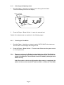
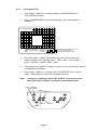
TEKKEN TAG OPERATORS MANUAL IT IS THE RESPONSIBILITY OF THE OPERATOR TO MAINTAIN CUSTOMER SAFETY AT ALL TIMES, AND IT IS IMPERATIVE THAT THE DETAILS SET OUT IN THIS MANUAL ARE FOLLOWED PRECISELY Part No. 90500070 Issue 1 Contents 1. SPECIFICATIONS ...................................................................................................... 3 2. MOVING THE MACHINE ............................................................................................ 4 3. INSTALLATION ........................................................................................................... 4 4. ADJUSTMENTS ......................................................................................................... 5 4-1 Entering the Test Mode ....................................................................................... 5 4-1-1 Selecting and Adjusting Items ....................................................................... 6 4-1-2 Finishing the Test Mode ................................................................................. 6 4-2 Display Test ......................................................................................................... 7 4-2-1 Convergence Test .......................................................................................... 8 4-2-2 Colour Bar Test .............................................................................................. 9 4-3 Switch Test ........................................................................................................ 10 4-4 Sound Test ........................................................................................................ 11 4-5 Game Options ................................................................................................... 12 4-6 Coin Options ...................................................................................................... 14 4-7 A.D.S. (Book Keeping) ...................................................................................... 16 4-8 DATA CLEAR .................................................................................................... 16 5. PCB CONNECTIONS ............................................................................................... 17 6. PARTS ...................................................................................................................... 18 Page 2 1. SPECIFICATIONS POWER SUPPLY:- 230volts AC AMBIENT OPERATING TEMPERATURE: +5°C TO +25°C MONITOR:- Hantarex 28 Polo Monitor COIN ACCEPTOR:- Mars CashFlow - 1 Channel DIMENSIONS:- 790(w) WEIGHT:- 175kg ACCESSORIES:- Keys: x 1200(d) x 2080(h) (Cash Door) ..................... 2 (Coin Door) ...................... 2 (Back Door) ...................... 2ea IEC Mains Lead ............................... 1 Operators Manual ........................... 1 Monitor Manual ............................... 1 CashFlow Documents ..................... 1 M6 Security Wrench ........................ 1 M4 Security Wrench ........................ 1 Page 3 2. MOVING THE MACHINE This machine is fitted with castors to make it easier to move. Take care when moving the machine on an inclined surface. The overall height of the machine is 2080mm. Take care of any overhead obstructions. (e.g. Light Fittings, Electric Cables etc.) 3. INSTALLATION This machine is designed for INDOOR USE ONLY. Do not install in the following places. 1. 2. 3. 4. 5. 6. Outdoors Direct Sunlight, places with excessive humidity or dust, places where there is water leakage, near air-conditioning or heating equipment, places with excessive heat or cold temperature. Places where it would be in the way of emergency exits or fire extinguishing equipment. Unstable places or places with excessive vibration. Places that are not level. This machine must not be cleaned with a water jet, or installed in an area where a water jet could be used. WARNING NEVER turn the power to the machine ON until installation has been completed. WARNING In order to prevent possible electric shocks, be sure that the machine is connected to the mains with a securely connected earthed plug. WARNING So that customers are not injured , ensure that there is at least 500mm separation between other machines or walls. CAUTION In order to avoid damage to the machine due to mis-operation, ensure that the voltage of the mains supply is 230volts AC. NOTE If the location site of this machine has a polished floor it is recommended that rubber pads are fitted under the level adjusters to prevent the machine sliding on the floor. In order to gain access to the Power Supply and CPU assemblies, make sure that the rear of the machine is separated from a wall or other machine by at least 500mm. Page 4 4. ADJUSTMENTS The following adjustments and tests can be made to this game. Item Reference Testing the Video and Adjusting the Monitor 4-2 Display Test (p7) Testing the Joysticks and Button Switches 4-3 Switch Test (p10) Testing the Sound 4-4 Sound Test (p11) Setting the Video Sync Not Used on This Cabinet Setting the Game Otions 4-5 Game Options (p12) Setting the Price of Play 4-6 Coin Options (p14) Book Keeping Data 4-7 ADS (p16) Resetting the Book Keeping 4-8 Data Clear (p16) 4-1 Entering the Test Mode Test Switch 1. To enter test mode, slide the TEST switch, located on the service bracket inside the coin door, to the ON position. The following screen will be displayed. DISPLAY TEST Display test (4-2 page 7) SWITCH TEST Switch test (4-3 page 10) SOUND TEST Sound test (4-4 page 11) JVS CABINET OPTIONS JVS cabinet options GAME OPTIONS Game options (4-5 page 12) COIN OPTIONS Coin options (4-6 page 14) Check play data (4-7 page 16) DATA CLEAR Data clear (4-8 page 16) EXIT & SAVE Finishing the test mode A.D.S. Page 5 4-1-1 1. Selecting and Adjusting Items Push the Player 1 Joystick up or down to scroll through the test items. The test will change to red on the display. Player 1 Joystick Start Switch Switch 1 Switch 2 Switch 4 Switch 5 Switch 3 2. Press the Player 1 Button Switch 1 to enter the selected test. Details of the adjustments are explained in the following pages. 4-1-2 Finishing the Test Mode 1. Push the Player 1 Joystick up or down to select EXIT & SAVE in the test menu. EXIT & SAVE on the display will change to red. 2. Press the Player 1 Button Switch 1. The test mode finishes and the game returns to normal play mode. Note: The test mode must be finished as described above. If the Test Mode is ended any other way, the changes made during the test mode will not be stored or be effective. The test mode cannot be ended by turning the test switch off only. If the Test switch is left in the ON position after testing is completed, the switch will have to be turned OFF and back ON to re-enter the Test Mode. Page 6 4-2 Display Test The following checks and adjustments are available in this mode:COLOUR EDIT: Adjustment of the colour and brightness output from the PCB. CONVERGENCE: Used for the adjustment of size, position and squareness of the monitor display. (Use monitor controls for adjustments). COLOUR BAR: Used for the adjustment of the shade and tone balance of the monitor. (Use monitor controls for adjustments). 1. Select DISPLAY TEST from the main test menu, (see 4-1-1 page 6), the following screen is displayed. Color edit screen CONVERGENCE PREVIOUS VALUE EXIT COLOR EDIT NEXT COLOR TEST EXIT Contrast Bright R Bright G Bright B : : : : : P-1 BUTTON 5 : P-1 BUTTON 4 : P-1 BUTTON 1 : P-1 START Reverts to values before changes made Color edit screen is displayed over the diagonal screen. * Pressing the Player 1 Switch 4 turns the Colour Edit On / Off CONVERGENCE ENTER COLOR EDIT: P-1 BUTTON 4 NEXT COLOR TEST : P-1 BUTTON 1 EXIT : P-1 START The color edit screen is not displayed Page 7 Switches the color edit mode on / off Go to the next test pattern Return to the test menu screen 4-2-1 Convergence Test 1. Press Player 1 Switch 1 to change between CONVERGENCE and COLOUR BAR screens. 2. On the CONVERGENCE screen the following cross hatch pattern is displayed. CONVERGENCE ENTER COLOR EDIT: P-1 BUTTON 4 NEXT COLOR TEST : P-1 BUTTON 1 EXIT : P-1 START Switches the color edit mode on / off Go to the next test pattern Return to the test menu screen 3. Each time Player 1 Switch 2 is pressed, the colour of the cross hatch pattern changes in the following order:- white > blue > red > purple > green > light blue > yellow > black > white . . . . . 4. If the pattern size, position or shape is incorrect, refer to the monitor manual for adjustment procedures. 5. Press Player 1 Switch 1 to change to the COLOUR BAR test or press Player 1 Start Switch to return to the Test Menu Screen. Note: If testing is completed, select EXIT & SAVE on the menu screen and press Player 1 Switch 1 to return to normal game mode. Player 1 Joystick Start Switch Switch 1 Switch 2 Switch 4 Switch 3 Page 8 Switch 5 4-2-2 Colour Bar Test 1. Select DISPLAY TEST from the main test menu, (see 4-1-1 page 6). 2. If the COLOUR BAR screen is not displayed, press Player 1 Switch 1 to change from CONVERGENCE to COLOUR BAR screen. The following screen is displayed. COLOR BAR Contrast Bright R Bright G Bright B : : : : Whole contrast Brightness (red) Brightness (green) Brightness (blue) Color bar (white) Color bar (red) Color bar (green) Color bar (blue) PREVIOUS VALUE EXIT COLOR EDIT NEXT COLOR TEST EXIT : P-1 BUTTON 5 : P-1 BUTTON 4 : P-1 BUTTON 1 : P-1 START Returns to original value Finish the color edit Go to the next test pattern Return to the test menu screen Each colour bar of white, red, green and blue is displayed with gradual shading. Press Player 1 Switch 2 to change the density from 32 > 16 > 8 > 4 > 2 > 32 . . . . . 3. Press the Player 1 Joystick up or down to select the item to be adjusted from Contrast, Bright R, Bright G, and Bright B 4. Press the Player 1 Joystick left or right to change the setting of the selected item. 5. Repeat items 3 and 4 for each item to be changed. 6. Press Player 1 Switch 1 to change to the CONVERGENCE test or press Player 1 Start Switch to return to the Test Menu Screen. Note: If testing is completed, select EXIT & SAVE on the menu screen and press Player 1 Switch 1 to return to normal game mode. Player 1 Joystick Start Switch Switch 1 Switch 2 Switch 4 Switch 5 Switch 3 Page 9 4-3 Switch Test 1. Select SWITCH TEST from the main test menu, (see 4-1-1 page 6), the following screen is displayed. P1 button switches 2 3 P2 8-direction joystick P2 start switch P2 button switches 1 2 3 SWITCH TEST P1 start switch 1P : 0000 2P : 0000 P1 8-direction joystick P1 button switches 1 4 Service switch of the cabinet SERVICE : OFF Test switch of the cabinet TEST SW : OFF DIP SW 1 : ON DIP SW 2 : OFF Option switches of the PC board COIN 1 : 0 COIN 2 : 0 Not used 5 P2 button switches 4 EXIT : P1-BUTTON4&5 Not used The number of activation of the coin counter (initially 0) 5 P1 button switch How to return to the test menu screen 2. The Joystick on the display will move as the Player Joystick is operated. The Button Switches on the display will be highlighted as the corresponding Player Button Switch is operated. The display for the other switches will change from OFF to ON as each switch is operated. 3. Press Player 1 Switches 4 and 5 together to return to the Test Menu Screen. Note: If testing is completed, select EXIT & SAVE on the menu screen and press Player 1 Switch 1 to return to normal game mode. Player 1 Joystick Start Switch Switch 1 Switch 2 Switch 4 Switch 5 Switch 3 Page 10 4-4 Sound Test 1. Select SOUND TEST from the main test menu, (see 4-1-1 page 6), the following screen is displayed. SOUND TEST SOUND : [000] STATUS : 0000 Sound number Status of sound output SPEAKER OUT : STEREO Current setting; mono/stereo SOUND PLAY : P1-BUTTON1 SET [MONAURAL] : P1-BUTTON2 EXIT : P1-START Produces a sound each time the switch is pressed Change the setting from mono to stereo How to return to the test menu screen 2. Press the Player 1 Joystick up or down to select the item to be adjusted. 3. Press the Player 1 Joystick left or right to change the setting of the selected item. 4. Repeat items 2 and 3 for each item to be changed. 5. Press Player 1 Start Switch to return to the Test Menu Screen. Note: If testing is completed, select EXIT & SAVE on the menu screen and press Player 1 Switch 1 to return to normal game mode. Item Test/Adjustment How to Operate Sound Each number produces a different sound used during the game Press the Player 1 Joystick left or right to change the number Sound Play Causes the sound selected above to be played. Press the Player 1 Switch 1 Set [Mono/Stereo] Sets the sound output in either Mono or Stereo mode. Press the Player 1 Switch 2 Stereo Sound Test Sound is played from the left speaker, right speaker, and then both speakers together. Select sound No. [001] and press Player 1 Switch 1 Player 1 Joystick Start Switch Switch 1 Switch 2 Switch 4 Switch 5 Switch 3 Page 11 4-5 Game Options 1. Select GAME OPTIONS from the main test menu, (see 4-1-1 page 6), the following screen is displayed. GAME OPTIONS <DEFAULTS IN GREEN> (a) (b) (c) (d) (e) (f) (g) (h) (i) (j) (k) (l) (m) (n) DIFFICULTY LEVEL : MEDIUM FIGHT COUNT<1P GAME> : 1 FIGHT COUNT<VS GAME> : 1 LIFE BAR<1P GAME> : +1 LIFE BAR<VS GAME> : +1 ROUND TIME : 99 GUARD DAMAGE : OFF GUARD DAMAGE : ON CHARACTER CHANGE AT CONTINUE : YES CHARACTER CHANGE AT VS GAME : NO MUSIC IN ATTRACT : YES EVENT MODE : OFF 4 PLAYERS MODE : OFF HIT COLOR : RED EXIT : P1-START 2. Press the Player 1 Joystick up or down to select the item to be adjusted. 3. Press the Player 1 Joystick left or right to change the setting of the selected item. 4. Repeat items 2 and 3 for each item to be changed. 5. Press Player 1 Start Switch to return to the Test Menu Screen. Note: If testing is completed, select EXIT & SAVE on the menu screen and press Player 1 Switch 1 to return to normal game mode. Player 1 Joystick Start Switch Switch 1 Switch 2 Switch 4 Switch 5 Switch 3 Page 12 (a) DIFFICULTY LEVEL (Diffulculty level for game play) EASY HARD MEDIUM VERY HARD ULTRA HARD (b) FIGHT COUNT <1P GAME> (The number of rounds to be cleared to win in 1 Player mode) 1 2 3 4 5 (c) FIGHT COUNT <VS GAME> (The number of rounds to be cleared to win in 2 Player mode 1 2 3 4 5 +1 +2 NORMAL +1 +2 60 90 99 (d) LIFE BAR <1P GAME> (Life gauge in 1 Player mode) -2 NORMAL -1 (e) LIFE BAR <VS GAME> (Life gauge in 2 Player mode) -2 -1 (f) ROUND TIME (Time for 1 round [seconds]) 30 40 (g) GUARD DAMAGE (Damage at guard) OFF (none) ON (a little) (h) NEUTRAL GUARD (Guard condition when the Joystick is in the centre) ON (Guard exists) OFF (No guard) (i) CHARACTER CHANGE AT CONTINUE (Changing characters at continue play) YES (Possible) NO (Not possible) (j) CHARACTER CHANGE AT VS GAME (Changing characters in 2 Player game when someone buys in) YES (Possible) NO (Not possible) (k) MUSIC IN ATTRACT (Sound played during the Attract Mode) YES (sound played) NO (No sound played) (l) EVENT MODE (Continuation after 2 Player game ended) OFF (Winner continue as 1 Player game) ON (Both players game over) (m) PAIR PLAY MODE (4 players control) Not available on this cabinet (n) HIT COLOUR (Red display effect at hit) GREEN (Changed to another colour RED (Exist) Page 13 4-6 Coin Options 1. Select COIN OPTIONS from the main test menu, (see 4-1-1 page 6), the following screen is displayed. COIN OPTIONS <DEFAULTS IN GREEN> (a) (b) (c) (d) (e) (f) (g) START COST: 1 COIN TO START CONTINUE COST: 1 COIN TO CONTINUE COIN CHUTE1 MECHANICAL VALUE: 1 COIN COUNT AS 1 COIN COIN CHUTE2 MECHANICAL VALUE: 1 COIN COUNT AS 1 COIN CREDIT MODE: COMMON COIN COUNTER: 1 COUNTER FREE PLAY: NO EXIT : P1-START 2. Press the Player 1 Joystick up or down to select the item to be adjusted. 3. Press the Player 1 Joystick left or right to change the setting of the selected item. 4. Repeat items 2 and 3 for each item to be changed. 5. Press Player 1 Start Switch to return to the Test Menu Screen. Note: If testing is completed, select EXIT & SAVE on the menu screen and press Player 1 Switch 1 to return to normal game mode. Player 1 Joystick Start Switch Switch 1 Switch 2 Switch 4 Switch 5 Switch 3 Page 14 NOTE: The price of play is set within the CashFlow validator. The START COST,, AND COIN CHUTE VALUE MUST all be set to 1 (a) START COST (The number coins required for 1 game) 1 2 3 4 5 6 7 8 9 (b) CONTINUE COST (The number of coins needed to play a continue game) 1 2 3 4 5 6 7 8 9 8 9 (c) COIN CHUTE 1 MECHANICAL VALUE (The number of coins to be added when the coin switch 1 activates) 1 2 3 4 5 6 7 (d) COIN CHUTE 2 MEC HANICAL VALUE (The number of coins to be added when the coin switch 2 activates) Not Used On This Cabinet (e) CREDIT MODE (Record of Credit) COMMON Either Start Sw itch removes one credit EACH ONE Not Used ON This Cabinet (f) COIN COUNTER (Allocation of coin counter signal) 1 COUNTER Only one coin counter used 2 COUNTERS Not Used On This Cabinet (g) FREE PLAY (Setting of Free Play) NO (Coins needed) YES (No coins needed) Page 15 4-7 A.D.S. (Book Keeping) 1. Select A.D.S from the main test menu, (see 4-1-1 page 6). 2. Press Player 1 Start Switch to return to the Test Menu Screen. Note: 4-8 If testing is completed, select EXIT & SAVE on the menu screen and press Player 1 Switch 1 to return to normal game mode. DATA CLEAR 1. Select DATA CLEAR from the main test menu, (see 4-1-1 page 6), the following screen is displayed. DATA CLEAR (a) CANCEL Return to the test menu screen (b) A.D.S CLEAR Clear the playing data only (c) RANKING CLEAR Initialize the ranking data (d) SET DEFAULTS ALL OPTIONS Reset all options to factory setting (e) ALL CLEAR Clear all the data recorded (b, c, d) Clear selected item Return to the test menu EXEC : P1-BUTTON1 EXIT : P1-START 2. Press the Player 1 Joystick up or down to select the item to be adjusted. 3. Press the Player 1 Switch 1 to clear the selected data. 4. Select CANCEL or press Player 1 Start Switch to return to the Test Menu Screen. Note: If testing is completed, select EXIT & SAVE on the menu screen and press Player 1 Switch 1 to return to normal game mode. Page 16 5. PCB CONNECTIONS JAMMA 56way Edge Connector Solder Side Terminal No 48way Extension Connector Part Side Solder Side Terminal No Part Side GND A 1 GND GND B 2 GND A2 B2 +5v C 3 +5v A3 B3 +5v D 4 +5v A4 B4 E 5 A5 B5 F 6 A6 B6 Polarizing Key H 7 Polarizing Key A7 B7 Coin Counter 2 j 8 Coin Counter 1 A8 B8 P2 Button 5 K 9 A9 B9 GND Speaker (-) L 10 Speaker (+) A 10 B 10 GND Audio (GND) M 11 Audio (+) A11 B11 Video GREEN N 12 Video RED A 12 B 12 Video SYNC P 13 Video BLUE A 13 B 13 Service Switch R 14 Video GND A 14 B 14 S 15 Test Switch A 15 B 15 Coin Switch 2 T 16 Coin Switch 1 A 16 B 16 P2 Start Switch U 17 P1 Start Switch A 17 B 17 P2 Lever UP V 18 P1 Lever UP A 18 B 18 P2 Lever DOWN W 19 P1 Lever DOWN A 19 B 19 P2 Lever LEFT X 20 P1 Lever LEFT A 20 B 20 P2 Lever RIGHT Y 21 P1 Lever RIGHT A 21 B 21 P2 BUTTON 1 Z 22 P1 BUTTON 1 A 22 B 22 P2 BUTTON 2 a 23 P2 BUTTON 2 A 23 B 23 P2 BUTTON3 b 24 P2 BUTTON 3 A 24 B 24 c 25 d 26 GND e 27 GND GND f 28 GND +12v Speaker R (-) Polarizing Key +12v P2 Button 4 P1 Button 4 Page 17 A1 B1 Speaker R (+) Polarixing Key P1 Button 5 6. PARTS Cabinet Parts Description Part No Mars CashFlow - single channel 98000041 Securdor w/Lock - Black 53100322 Hantarex 28" Polo Monitor 84000026 Front Glass - Bronze 31000022 Schaffner Mains-In Filter Assy 66000016 Schaffner Boot 66000017 Fuse 20mm 5A Quick-Blo 63500500 Interlock Switch 60000006 Interlock Switch cover 39000028 M16 Adjustable Foot 88300079 Coin Meter 3.5-6v Panel Mount 65000002 SwitchMode Power Supply 83000040 Yellow Push Button Switch Assy 60200052 Black Push Button Switch Assy 60200054 Red Push Button Switch Assy 60200051 Blue Push Button Switch Assy 60200053 Green Push Button Switch Assy 60200267 White Push Button 1 Player Switch Assy 60200055 White Push Button 2 Player Switch Assy 60200056 Page 18 Decals and Plastics Description Part No Cabinet Decal LHS - Upper 40000530 Cabinet Decal LHS - Lower 40000531 Cabinet Decal RHS - Upper 40 000532 Cabinet Decal RHS - Lower 40000533 Cabinet Decal LHS - Front 40000297 Cabinet Decal RHS - Front 40000298 400000 61 Namco Decal Cabinet Front Decal - Namco 40000469 Character Plexi - Tekken Tag 30000238 Header Vac-Form 46000244 Header Acrylic - Tekken Tag 30000240 Play Panel Overlay -Tekken Tag 33000004 Tekken Tag - Promotional Poster 40000534 Page 19