1
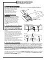
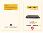
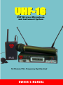
UHF-16
UHF Wireless Microphone
and Instrument System
16 Channel PLL Frequency Synthesized
OWNER’S MANUAL
TABLE OF CONTENTS
INTRODUCTION
Using this Manual ................................................ 4
SYSTEM FEATURES
UHF 16 Receiver ................................................. 5
UB-16 and UH-16 Transmitters ............................ 5
OPERATING INSTRUCTIONS
UHF 16 Receiver
1. Mounting the Receiver ..................................... 6
a. Table mounting ............................................ 6
b. Rack Mounting a Single Receiver ............... 6
c. Rack Mounting 2 Receivers Side by Side .... 6
2. Installing Antennas ........................................... 7
3. Powering the Receiver ..................................... 7
4. Choosing an Operating Frequency .................. 8
5. Mute Adjustment .............................................. 8
6. Diversity Operation .......................................... 8
7. Connecting Audio Output ................................. 8
a. Instrument Connection ................................ 9
b. Microphone Connection ............................... 9
8. Locking the Keyboard ...................................... 9
9. Simultaneous Multi-Channel Operation ........... 9
UH-16 Handheld Microphone Transmitter
1. Powering the Transmitter ............................... 10
2. Selecting the Operating Frequency ............... 10
3. Selecting the Tone Squelch™ Mode/
Activity Indicator ............................................. 10
4. Locking the Keyboard .................................... 10
5. Microphone Operation ................................... 11
CHANNEL DISPLAY AND UP/DOWN
BUTTONS OPERATION
1. UHF-16 Receiver ........................................... 15
a. Changing the Channel Assignment ........... 15
b. Selecting Tone Squelch™ Mode ............... 15
c. Selecting Keyboard Lock ........................... 15
d. Battery Status Icon Operation ................... 15
2. UH-16 and UB-16 Transmitters ...................... 15
a. Changing the Channel Assignment ........... 15
b. Selecting Tone Squelch™ Mode/
Activity Indicator ......................................... 15
c. Selecting Keyboard Lock ........................... 15
FREQUENCY GUIDE ......................... 16
SPECIFICATIONS
UHF 16 System .................................................. 17
UHF-16 Receiver ............................................... 17
UB-16 & UH-16 Transmitters ............................. 17
SERVICE FOR YOUR NADY WIRELESS
SYSTEM
U.S. .................................................................... 18
International ....................................................... 18
UB-16 Bodypack Transmitter
1. Powering the Transmitter ............................... 12
2. Selecting Input for Operation ......................... 12
3. Connecting the Audio Source ........................ 12
4. Turning on the Transmitter ............................. 12
5. Selecting the Operating Frequency ............... 13
6. Selecting the Tone Squelch™ Mode/
Activity Indicator ............................................. 13
7. Locking the Keyboard .................................... 13
8. Microphone and Instrument Operation .......... 13
a. Instrument Use .......................................... 13
b. Microphone Use ........................................ 14
9. Cautions ......................................................... 14
a. Feedback ................................................... 14
b. Microphone Damage ................................. 14
c. No Audio .................................................... 14
3
I NTRODUCTION
Thank you for choosing the Nady UHF-16 wireless system, and congratulations on your choice. The Nady
UHF-16 system is by far the best performance and price value available in professional UHF wireless.
Offering clear channel operation on the wide open, uncluttered UHF band for interference-free
performance in any application or locale, the UHF-16 delivers 16 user switchable, frequency synthesized
channels in pre-programmed groups in the 726 - 865 MHz range.
The UHF-16 systems feature Nady’s proprietary companding and low noise circuitry for an industry best
120 dB Dynamic Range, and the clearest, most natural sound available in wireless today.
Using this Manual
This booklet gives instructions for the operation of the UHF-16 system, including the UB-16 Bodypack
Transmitter, and the UH-16 Handheld Microphone Transmitter. Please read this instruction booklet
completely before operating your system, and refer to the Nady UHF-16 Frequency Guide for the
frequency band(s) and channels utilized by your system.
This manual will first explain the features of the UHF-16 and will then take you step by step in instructing
you how to operate your new system. Each section will give you detailed information. Also included in this
manual is a frequency selection chart, complete system specifications, and servicing information.
4
SYSTEM FEATURES
UHF-16 Receiver
• State-of-the-art PLL synthesized 16 channel selection, user switchable
• Unsurpassed UHF performance with 120 dB dynamic range and operation up to 500 feet line-of-sight
• Rugged half-rack UHF-16 receiver with dual removable antennas (for convenient optional remote
placement), 16 user switchable UHF frequencies and DigiTRU Diversity™ proprietary digital processing
circuitry for eliminating dropouts and maximizing range
• Sophisticated IF filtering for multiple UHF-16 system operation in the same location simultaneously
• User-selectable Tone Squelch™ for protection from RF interference
• Front panel back-lit LCD display indicates the channel/frequency selected, received RF and AF levels,
A/B diversity status, and transmitter low-battery alert
• Convenient UP/DOWN buttons for easy channel selection
• Front panel ON/OFF button (with Power On LED indicator), Squelch (mute) adjust and Volume control for
ease of operation
• Back panel balanced XLR fixed mic level and adjustable unbalanced 1/4" jack audio outputs, and BNC
jacks for dual antennas
• Externally powered with 12 VDC (500 mA) AC adapter
• Optional rack kits enable single or side-by-side rack mounting.
UB-16 and UH-16 Transmitters
Choice of transmitters: UH-16 handheld or UB-16 bodypack, both 16-channel selectable
• UH-16 and UB-16 both operate on 2 AA batteries for the longest reliable and economical battery life.
• UH-16 handheld is a sleek, durable unit with internal antenna (with no archaic, unattractive antenna
protrusion) and the superior Nady DM-10D neodymium dynamic cartridge for clear, powerful audio,
maximum feedback rejection, and minimal handling noise.
• UB-16 bodypack is a versatile unit with unique 3-way input switch allowing its operation selectively as an
instrument, lavalier mic or headworn mic transmitter (with convenient DC phantom powering in the mic
settings for condensers). An input level control allows optimal audio gain adjustment, and a locking 3.5
mm jack provides secure connection to the instrument cable, lavalier or headworn mic cord.
• Both the UH-16 and UB-16 transmitters feature OFF/STANDBY/On controls, low battery LED indicators,
and offer easy channel selection via UP/DOWN buttons and a 2-segment LCD Channel display.
5
OPERATING INSTRUCTIONS
UHF-16 Receiver
1. Mounting the Receiver
a. Table Mounting
To mount a receiver on a table or other horizontal surface, attach the four supplied rubber feet to the
bottom corners of the receiver and place the receiver on the mounting surface.
b. Rack Mounting a Single Receiver
If you want to rack mount a single receiver in an audio equipment rack, contact the Nady Systems Service
Department (see SERVICE FOR YOUR NADY
WIRELESS, page 18) for an optional RMK-16S
(6a)
SINGLE RACK MOUNTING KIT (6a) and proceed as
follows:
1. Attach the rack ears to the 2 holes on each
side of the receiver with the supplied screws
and mount the unit in the 19” audio equipment
rack.
2. If you wish to also front mount the antennas, order the additional FMK-16S FRONT MOUNT
CONVERSION KIT (6b) also from the Nady Service Department when ordering the RMK-16S.
c. Rack Mounting 2 Receivers Side by Side
If you want to rack mount 2 receivers side-by-side in an audio equipment rack, contact the Nady Systems
Service Department (see SERVICE FOR YOUR NADY WIRELESS, page 18) for an optional RMK-16D
DOUBLE RACK MOUNTING KIT (6c) and proceed as follows:
1. Remove the covers of both receivers by
removing the 4 screws on the bottom plate
as shown.
2. Join the 2 receivers together with the
supplied bolts and nuts, while also joining
the back of the receivers with the supplied
double side tape as shown
(6c)
3. Attach the rack ears to the 2 holes on the
outer sides of the receivers with the
supplied screws and mount the units in the
19” audio equipment rack.
4. If you wish to also front mount the antennas,
order the additional FMK-16D FRONT
MOUNT CONVERSION KIT (6d) from the
Nady Service Department when ordering
the RMK-16D. This kit includes a passive antenna splitter/combiner so that the 2 CH A and CH B
antennas for both side-by-side receivers (4 total) are combined into single CH A and CH B
antennas on the front panel as shown.
(6b)
(6d)
(6e)
6
OPERATING INSTRUCTIONS
UHF-16 Receiver
(5)
Install antennas by connecting the
two antennas included with your
system, or optional remote
antennas, to the two each BNC
RF TWIST-ON CONNECTORS
(5) located on the back of your
UHF-16 receiver. If using either
single or side-by-side front panel antenna mounting, as described above, attach either the supplied or
optional remote antennas to the FRONT PANEL BNC CONNECTORS (6e) as shown. For best
performance, point the antenna tips away from each other at a 90° angle (45° from vertical axis).
2. Installing Antennas
UHF-16 BACK PANEL
(5)
(4)
(3)
(2)
(1)
(7)
UHF-16 FRONT PANEL
(8)
(9) (10)
(11)
(12)
(13)
3. Powering the Receiver
Plug the AC/DC ADAPTOR (1) provided in the 12 VDC INPUT JACK (2) on the back of the receiver. Then
plug the adapter into an AC outlet. (Note: Any center positive 12V DC source with 500 mA capability can
also be used.)
Turn the VOLUME CONTROL (7) counterclockwise to minimum and press the POWER SWITCH (8) ON.
The POWER ON LED (9) will now light, and the receiver is operational.
The LCD DISPLAY (11) should also be lit. The AUDIO LEVEL (11b) and RF LEVEL (11a) meter icons will
not display until your transmitter is turned on, your frequency selection common to both the transmitter and
receiver is made, and the system is operational. The AUDIO LEVEL METER (11b) will display when you
then speak into the attached microphone or play the connected instrument.
7
OPERATING INSTRUCTIONS
UHF-16 Receiver
4. Choosing an Operating Frequency
Choose an operating frequency by selecting any of the 16 UHF operating frequencies available in the band
provided, using the UP/DOWN BUTTONS (12). The CHANNEL SELECTED (11d) and OPERATING
FREQUENCY (11f) icons in the LCD DISPLAY
(11d)
(11a)
(11b)
(11c)
(11) indicate the channel and frequency you
have selected. You must also set your
transmitter UP/DOWN BUTTONS (20,25) to
the same channel you choose on the receiver.
(See UH-16 or UB-16 TRANSMITTER
OPERATING INSTRUCTIONS, page 10 & 13
and CHANNEL DISPLAY AND UP/DOWN
BUTTON OPERATION, page 15). For a listing
of the frequencies in each of the 3 available
bands, see page 16.
(11e)
(11f)
5. Mute Adjustment
The receiver has two audio mute circuits.
a. The Tone Squelch™ blocks the audio noise when the channel signaling tones are not present. It helps
avoid interferences from unwanted transmissions. This feature is strongly recommended for situations
where the transmitter is turned on and off during use. Without Tone Squelch™, an unwanted signal may
enter your inactive receiver when your transmitter is switched off. You then risk a pop or disruptive noise
coming from your sound system. This type of interference is eliminated by the Tone Squelch™. The
receiver detects a tone signal coming from your transmitter, which opens the squelch, allowing your
modulated signal to be heard. This feature is selectable and not recommended for applications where the
transmitter will always be on, or for use with instruments.
The Tone Squelch™ mode can be configured with the Up/Down buttons. See CHANNEL DISPLAY AND
UP/DOWN BUTTON OPERATION, page 15.
(Note: If the receiver is configured for Tone Squelch™ mute, the transmitter must also be configured to
send the tones, otherwise the receiver audio will remain muted. The signaling tones are also used to
display the transmitter battery status. If the Tone Squelch™ is defeated, this function will not be
operational.)
b. The Receive Level Mute blocks audio noise when the received signal level is too low, or interfering
transmissions are high.
A MUTE (RF SQUELCH) CONTROL (13) is provided on the front panel. This control should be adjusted
counterclockwise to the minimum position at which there is no audio output signal from the receiver when
your transmitter is not in use. This is the most sensitive setting for your receiver and offers the maximum
operating range. However, in areas of high RF activity, the mute may need to be adjusted. When the
transmitter is off and the receiver’s RECEIVED RF LEVEL METER (11a) icon flickers or displays one or
more segments, and/or white noise (hiss) is heard at the receiver output, the MUTE CONTROL (13) should
be turned clockwise until the noise is muted (squelched). Turning the MUTE CONTROL too far clockwise
will reduce operating range but will yield a quieter mute function. Note that the MUTE CONTROL operates
independent of the RF LEVEL METER so that adjusting the MUTE will not affect any readings at the RF
LEVEL METER.
6. Diversity Operation
During operation only one of the A or B DIVERSITY STATUS ICONS (11e) will be lit, indicating the
receiver’s DigiTru Diversity™ circuitry is selecting antenna input A or B for the best signal. This is normal
and ensures that the received audio will not be interrupted. Sometimes, especially at ranges greater than
75 feet, the squelch circuit will activate in certain locations of the transmitter with respect to the receiver.
Such areas are called “null spots” and indicate that the transmitter is out of range for that given location,
and the user should move closer to the receiver or to another area to re-establish the radio link.
8
OPERATING INSTRUCTIONS
UHF-16 Receiver
7. Connecting Audio Output
The UHF-16 receiver provides both a fixed mic level BALANCED AUDIO OUTPUT XLR (4) and an
adjustable 1/4” line level LINE OUTPUT JACK (3).
(Note: As when making any connection, make sure the amplifier or mixing board volume is at the minimum
level before plugging in the receiver to avoid possible sound system damage.)
a. Instrument Connection (using the UB-16 transmitter in the “Instrument” setting)
Insert an audio cord with a 1/4" mono phone plug in the LINE OUT JACK (3) on the rear panel of the
receiver. Plug the other end of the cord into an amplifier, effects, or mixing board. Adjust the VOLUME
CONTROL (7) on the UHF-16 receiver clockwise to about 3/4 full, until the volume level is comfortable for
your application. This setting is roughly equivalent to a direct instrument cord connection. Turning the
volume up to MAX will provide 4 dB gain over a cord.
b. Microphone Connection (using the UH-16 handheld microphone transmitter, or the UB-16 transmitter
with either a headworn or lavalier microphone). For microphones, use either the BALANCED MIC OUTPUT
XLR (4) or the 1/4" line level LINE OUT JACK (3).
Plug an XLR connector into the BALANCED XLR OUTPUT (4) jack on the rear of the unit and plug the
other end into your amplifier or mixing board. For your convenience, the XLR output level is preset at the
factory for MIC level and is not adjustable with the receiver VOLUME CONTROL (7).
(Note: Make sure the volume is turned down when making connections.)
To use the 1/4" LINE OUT socket, follow the instructions for the Instrument Connection (above), except
start the receiver VOLUME CONTROL (7) at 1/2 MAX and adjust until the volume level is optimal. If the
volume is set too high, you may overload your mixer or amp.
The UHF-16 receiver is equipped with an AF DISPLAY ICON (11a), which displays up to 4 segments,
depending on the strength of the audio signal from the transmitter. Occasional flickering of the 4th bar
segment of this display on loud inputs to the transmitter is normal. If this segment displays continuously,
decrease the volume to the transmitter or overload distortion may result.
Your UHF-16 receiver is now operational and ready to use. Now that you have completed the above steps,
proceed to instructions for the Nady UHF-16 transmitter included with your system.
(Note: Only one transmitter can be used with one UHF-16 receiver. It is not possible to use two transmitters
on the same frequency and mix the output of these transmitters into one wireless receiver. If you have any
questions, please contact the Nady Systems Customer Service Department. See SERVICE, page 18.)
8. Locking the keyboard
To avoid accidental reconfiguration of the Channel setting or Tone Squelch™, the keyboard can be locked
by holding both the UP and DOWN BUTTONS (12) at the same time for 3 seconds. See the CHANNEL
DISPLAY AND UP/DOWN BUTTON OPERATION, page 15.
9. Simultaneous Multi-Channel Operation
For simultaneous operation of up to 4 –5 channels in a given application and in the same band, use the
procedure outlined above for setting up each channel, ensuring a different frequency for each system.
Operation of a greater number of channels simultaneously can sometimes be more difficult as the channel
combinations must be chosen with care to avoid intermodulation interference between the channels, which
involves more planning than just selecting different frequencies. For additional help and tips to enable more
complicated multi-channel simultaneous operation, contact the Nady Service Department for more
information. (see SERVICE FOR YOUR NADY WIRELESS, page 18).
9
OPERATING INSTRUCTIONS
UH-16 Handheld Microphone Transmitter
1. Powering the Transmitter
Slide open the BATTERY COMPARTMENT COVER (14) and remove, exposing the BATTERY
COMPARTMENT (15). Insert 2 fresh AA ALKALINE BATTERIES (16), observing the correct polarity as
marked, and slide the COVER back, closing the BATTERY COMPARTMENT.
Two fresh alkaline AA Batteries
can last up to 12 hours in use, but
in order to ensure optimum
performance, it is recommended
that you replace the batteries after
every 8-10 hours of use.
(16)
(15)
All controls are at the base of the
(14)
microphone. Turn on the UH-16 by
sliding the OFF/STANDBY/ON
SWITCH (17) to the STANDBY
position (transmitter on, audio
muted) or the ON position
(transmitter and audio both on).
The BATTERY INDICATOR LED
(18) will give a single quick flash, indicating usable battery strength. In the case of dead or low batteries,
the LED will either not go on at all, or will stay on continuously, indicating that the batteries should be
replaced with fresh ones. If the Tone Squelch™ is activated on both transmitter and receiver, the LOW TX
BATTERY ICON (11c) on the receiver’s LCD DISPLAY (11) will switch from the battery OK to the LOW
battery mode. See CHANNEL DISPLAY AND UP/DOWN BUTTON OPERATION, page 15 and UHF-16
OPERATING INSTRUCTIONS, page 8. The channel
number on the CHANNEL LED DISPLAY (19) will
(19)
extinguish in 10 seconds. The activity indicator
(18)
“ ’’ or “
’’ LED will remain on in the DISPLAY. See
CHANNEL DISPLAY AND UP/DOWN BUTTON
OPERATION, page 15.
2. Selecting the Operating Frequency
In order for the system to operate properly, the same
channel (frequency of operation) must be selected for the
UH-16 transmitter as was chosen for the UHF-16 receiver.
Press either the UP or DOWN CHANNEL SELECT
BUTTON (20) until the channel number indicated on the
2-segment CHANNEL LED DISPLAY (19) matches that of
the UHF-16 receiver.
(20)
(20)
(17)
3. Selecting the Tone Squelch™ Mode/Activity Indicator
Hold both the UP and DOWN BUTTONS (20) at the same time for 1 second. The Tone Squelch™ will cycle
from On to Off. See the CHANNEL DISPLAY AND UP/DOWN BUTTON OPERATION, page 15.
(Note: If the receiver is configured for Tone Squelch™ mute, the transmitter must also be configured to
send the tones, otherwise the receiver audio will remain muted. The signaling tones are also used to
indicate the transmitter battery status on the receiver BATTERY ICON (11c) display. If Tone Squelch™ is
defeated, this function will not be operational.)
10
OPERATING INSTRUCTIONS
UH-16 Handheld Microphone Transmitter
4. Locking the Keyboard
To avoid accidental reconfiguration of the Channel setting or Tone Squelch™, the keyboard can be locked
by holding both the UP and DOWN BUTTONS (20) at the same time for 3 seconds. See the CHANNEL
DISPLAY AND UP/DOWN BUTTON OPERATION, page 15.
5. Microphone Operation
The microphone is now ready to use. The RECEIVED RF LEVEL (11a) icon and either the A or B
DIVERSITY STATUS ICONS (11e) on the UHF-16 receiver should now be lit, indicating a received signal
from the transmitter. The receiver TX LED INDICATOR (10) should be on. When ready to speak, slide the
OFF/STANDBY/ON SWITCH (17) to the ON position. Adjust the volume of the receiver as per the Audio
Output Microphone Connection section of the above UHF-16 receiver instructions.
(Note: Observe care in selecting P.A. volume, transmitter location and speaker placement so that acoustic
feedback, howling or screeching, will be avoided.)
The UHF-16 receiver is equipped with an AF DISPLAY (11a) icon, which displays up to 4 segments,
depending on the strength of the audio signal from the transmitter. Occasional flickering of the 4th bar
segment of this display on loud inputs to the transmitter is normal. If this segment displays continuously,
and/or distortion is heard, decrease the volume to the transmitter. Due to the wide available dynamic range,
generally no adjustment will ever be needed for the transmitter input gain. There is a control under the mic
ball assembly available for rare cases where it’s desirable to make an input gain adjustment. For
instructions on how to access this internal control, please contact the Nady Systems Customer Service
Department. See SERVICE, page 18.
(Note: The microphone element can easily be destroyed by the buildup of salts and minerals from
perspiration and saliva. It is good practice to put a windscreen on the mic element at all times to protect it.)
11
OPERATING INSTRUCTIONS
UB-16 Bodypack Transmitter
1. Powering the Transmitter
Slide open the BATTERY COMPARTMENT (21) and insert 2 fresh AA ALKALINE BATTERIES (22),
observing the correct polarity. Two fresh
alkaline batteries can last up to 12
(22)
hours in use, but in order to ensure
(21)
optimum performance, it is
recommended that the battery be
replaced after 8-10 hours of use.
2. Selecting Input for
Operation
The UB-16 is equipped with an INPUT
SELECTOR SWITCH (23) in the battery
compartment for selecting the type of
audio input you will be supplying to the
transmitter. Select from the choice of
three positions: GT (for guitar, bass,
etc.) / HM (for headworn mic)/ LT (for
lavalier mic).
(34)
(23)
Inside Battery Compartment
3. Connecting the Audio Source
The UB-16 is provided with a 3.5 mm LOCKING
JACK (27) for connecting the audio input
selected. Connect either the INSTRUMENT (31)
cord or the HEADWORN MIC (32) or LAVALIER
MIC (33) cord as desired, according to the input
selected.
To secure the connection, turn the slip ring on
the plug clockwise to thread it on the jack. To
unplug, reverse the process. Slip the transmitter
into a pocket or CLIP (34) it on to your clothes or
instrument strap (if using the UB-16 as an
instrument transmitter).
(Note: Use only the input audio source as per the
input selected with the AUDIO INPUT
SELECTOR SWITCH or the audio will not be
optimal– a muddy or distorted sound may result.)
(25)
(24)
Top View
(29)
(26)
(30)
(28)
(27)
4. Turning on the Transmitter
Turn on the UB-16 by sliding the OFF/STANDBY/ON SWITCH (28) to the STANDBY position (transmitter
on, audio muted) or the ON position (transmitter and audio both on). The BATTERY INDICATOR LED
(30) will give a single quick flash, indicating usable battery strength. In the case of dead or low batteries,
the LED either will not go on at all or will stay on continuously, indicating that the batteries should be
replaced with fresh ones. If the Tone Squelch™ is activated on both transmitter and receiver, the LOW TX
BATTERY ICON (11c) on the receiver’s LCD DISPLAY (11) will switch from the battery OK to the LOW
battery mode. See CHANNEL DISPLAY AND UP/DOWN BUTTON OPERATION, page 15 and UHF-16
OPERATING INSTRUCTIONS, page 8.
Inside the cover, the channel number on the CHANNEL LED DISPLAY (24) will extinguish in 10 seconds.
The activity indicator “ ’’ or “
’’ LED will remain on in the DISPLAY. See CHANNEL DISPLAY AND
UP/DOWN BUTTON OPERATION, page 15.
12
OPERATING INSTRUCTIONS
UB-16 Bodypack Transmitter
5. Selecting the Operating Frequency
(31)
In order for the system to operate properly, the same channel
(frequency of operation) must be selected for the UB-16 transmitter as
was chosen for the UHF-16 receiver. Press either the UP or DOWN
CHANNEL SELECT BUTTON (25) until the channel number indicated
on the 2-segment CHANNEL LED DISPLAY (24) matches that of the
UHF-16 receiver.
6. Selecting the Tone Squelch™ Mode/
Activity Indicator
Hold both the UP and DOWN BUTTONS (25) at the same time for 1
second. The Tone Squelch™ will cycle from On to Off. See the
CHANNEL DISPLAY AND UP/DOWN BUTTON OPERATION, page 15.
(Note: If the receiver is configured for Tone Squelch™ mute, the
transmitter must also be configured to send the tones, otherwise the
receiver audio will remain muted. The signaling tones are also used to
display the transmitter battery status.)
7.
Locking the Keyboard
To avoid accidental reconfiguration of the Channel setting or Tone
Squelch™, the keyboard can be locked by holding both UP and DOWN
BUTTONS (25) at the same time for 3 seconds. See the CHANNEL
DISPLAY AND UP/DOWN BUTTON OPERATION, page 15.
8.
(32)
(33)
Microphone and Instrument Operation
The transmitter is now ready to use. The RECEIVED RF LEVEL ICON
(11a), and either the A or B DIVERSITY ICON (11e) on the UHF-16
receiver should now be lit, indicating a received signal from the
transmitter. The receiver TX LED INDICATOR (10) should be on.
a. Instrument Use.
Plug the 1/4" phone plug from the INSTRUMENT (31) cord into the instrument. Verify that the INPUT
SELECTOR SWITCH (23) is in the GT position. When ready to play, slide the audio OFF/STANDBY/ON
SWITCH (28) to the ON position. Adjust the volume of the receiver as per the Audio Output Instrument
Connections section of the preceding UHF-16 receiver instructions.
(Note: The INPUT LEVEL CONTROL (26) is deactivated and not used when the UB-16 is in GT, instrument
mode. Levels should be adjusted with the volume control of your instrument.)
The UHF-16 receiver is equipped with an AF DISPLAY (11a) icon, which displays up to 4 segments,
depending on the strength of the audio signal from the transmitter. Occasional flickering of the 4th bar segment
of this display on loud inputs to the transmitter is normal. If this segment displays continuously, turn down the
instrument volume, or noticeable distortion may result. Experiment and set for maximum possible gain without
audible distortion on the high level peaks. (Note: Turning down the gain or instrument volume too much can
compromise the signal-to-noise and is not recommended.)
(Note: Scratchy noises can sometimes occur when some electric guitars with dirty pots or connections are
used with any wireless system. Therefore, the supplied INSTRUMENT (23) cord has a factory installed
capacitor inside the 1/4" plug. This capacitor provides first order filtering of the RF signal from the cord into the
guitar and eliminates virtually all scratchy noises. Should your equipment still give you scratchy noises, we
suggest these steps to eliminate them:
1) Make sure all guitar volume and tone pots are clean and all contacts are solid–this is very important.
2) Solder a 47pf capacitor across the hot to ground terminals of the guitar’s volume and tone pots to provide
extra filtering.)
13
OPERATING INSTRUCTIONS
UB-16 Bodypack Transmitter
b. Microphone Use (with either a lavalier or headworn microphone)
Secure the connection from the LAVALIER (33) or HEADWORN MIC (34) cord by turning the slip ring on
the plug into the transmitter clockwise to thread it on to the jack. To unplug, reverse the process. To use
the lavalier mic, attach it at chest level. Do not place it too close to the mouth–a distance of about six
inches usually works best. To use the headworn mic, place it on the head and adjust the boom so that the
mic is about one inch to the side of the front of the mouth.
When ready to speak, verify that the INPUT SELECTOR SWITCH (23) is in either the HM position (for a
connected headworn mic) or the LT position (for a lavalier mic) and slide the OFF/STANDBY/ON SWITCH
(28) to the ON position. Adjust the volume of the receiver as per the Audio Output Microphone
Connection section of the preceeding UHF-16 receiver instructions. For optimum performance, an INPUT
LEVEL CONTROL (26) is provided. Adjust the gain by turning the control with the supplied small slotted
screwdriver. For lavalier mic use, it is recommended that the level be set at about 2/3 maximum. For
headworn mic use, it may be advisable to turn the gain down somewhat, depending on the volume levels
expected. In either application, experiment and set for maximum possible gain without audible distortion
on the high level peaks.
(Note: Turning down the gain too much can compromise the signal-to-noise and is not recommended.)
9.
Cautions
a. Feedback
Observe care in selecting P.A. volume, transmitter location and speaker placement so that acoustic
feedback, howling and screeching, will be avoided. Please also note the pickup pattern characteristics of
the microphone selected. Omnidirectional mics pick up sound equally from all directions, and are prone to
feedback if not used carefully. Unidirectional mics are more resistant to feedback, but pick up sound
sources best that are directly in front of the mic. Also, mics that are farther from the sound source, such as
lavaliers, require more acoustic gain and thus are also more prone to feedback than close-source mics
such as handheld or headworn models that are used close to the mouth.
b. Microphone Damage
The headset or lavalier microphone element can easily be destroyed by the buildup of salts and minerals
from perspiration and saliva. It is good practice to put a windscreen on the mic element at all times to
protect it.
c. No Audio
If the receiver is configured for Tone Squelch™ mute, the transmitter must also be configured to send the
tones, otherwise the receiver audio will remain muted. See preceding Mute Adjustment section, page 8.
14
CHANNEL DISPLAY AND
UP/DOWN BUTTON OPERATION
1. UHF-16 Receiver
Operation of Channel Display, Battery Status, Up and Down buttons, Keyboard Lock, and Tone Squelch™
a. Changing the Channel Assignment
Press Up or Down button to change channels.
b. Selecting Tone Squelch™ Mode
Hold both Up and Down buttons at the same time for 1 second. Tone Squelch™ will cycle from On to Off.
The presence or absence of the word “Channel” indicates the Tone Squelch™ mode.
If the receiver Tone Squelch™ is enabled, it must also be enabled on the transmitter otherwise the audio
will remain muted.
UNLOCKED
LOCKED
c. Selecting Keyboard Lock
Hold both Up and Down buttons at the same time for 3
seconds. Keyboard lock will cycle from Locked to Unlocked.
The “DOT” to the right of the number indicates the keyboard is
locked.
d. Battery Status Icon Operation
The Battery Icon indicates the condition of the battery in the
remote transmitter. Note that the Battery Icon will not display if
the Tone Squelch™ is disabled.
Battery OK
Battery LOW
2. UH-16 and UB-16 Transmitters
Operation of Channel Display and Up and Down buttons, Keyboard Lock, and
Tone Squelch™
a. Changing the Channel Assignment
Press Up or Down button to change channels.
The Channel number indicator will vanish after 10 seconds. The Tone
Squelch™ indicator and Keyboard Lock indicator will show that the transmitter is On.
b. Selecting Tone Squelch™ Mode / Activity Indicator
Hold both Up and Down buttons at the same time for 1 second.
Tone Squelch™ will cycle from On to Off.
The “ ’’ or “
’’ will remain on continuously and acts as an
activity indicator to show that the transmitter is on.
Tone ON
If the receiver Tone Squelch™ is enabled, it must also be enabled
on the transmitter otherwise the audio will remain muted.
c. Selecting Keyboard Lock
Hold both Up and Down buttons at the same time for 3 seconds. Keyboard
lock will cycle from Locked to Unlocked.
15
Tone OFF
FREQUENCY GUIDE
The UHF 16 system is available with a choice of three frequency bands, each with 16 user-selectable
frequencies. Select the band and frequencies appropriate to the area/country in which the system is to be
used.
Channel
U.S.
Band 1
U.S./Europe
Band 2
Europe
Band 3
1
726.10 MHz
793.40 MHz
846.20 MHz
2
726.50 MHz
794.00 MHz
846.60 MHz
3
727.00 MHz
796.60 MHz
847.10 MHz
4
727.60 MHz
799.50 MHz
847.80 MHz
5
728.30 MHz
801.10 MHz
848.80 MHz
6
729.30 MHz
802.80 MHz
849.50 MHz
7
731.40 MHz
804.90 MHz
850.90 MHz
8
732.35 MHz
805.85 MHz
851.85 MHz
9
734.00 MHz
807.45 MHz
853.45 MHz
10
735.40 MHz
808.85 MHz
854.85 MHz
11
736.60 MHz
810.05 MHz
856.05 MHz
12
739.10 MHz
812.55 MHz
858.55 MHz
13
739.90 MHz
813.35 MHz
859.35 MHz
14
742.60 MHz
816.05 MHz
861.35 MHz
15
744.15 MHz
817.60 MHz
862.05 MHz
16
745.95 MHz
819.05 MHz
863.60 MHz
16
SPECIFICATIONS
UHF 16 System
Operating Frequency Range:
16 channels switchable in pre-programmed bands
up to 26 MHz wide in the 726-865 MHz range
(country dependent)
Freq. Synthesized:
PLL system with frequency stability <0.005%
Frequency Response:
30 HZ-15 KHZ ±3 dB
Dynamic Range:
120 dB
Harmonic Distortions:
<0.5%
Modulation:
FM ±25 KHz nominal
Operating Range:
250 feet typical (depending on site conditions) up to
500+ feet optimum line-of-sight
UHF-16 Receiver
Receiving System:
Dual conversion superheterodyne with DigiTRU
Diversity™
Sensitivity:
-107 dBm, nominal
Selectivity:
60 dB nominal ± 75 KHz offset
Image Rejection:
-70 dB, minimum
Spurious Rejection:
65 dB, nominal
Mute Threshold:
-90 dBm, adjustable
Audio Output Level:
Unbalanced output: 360 mV, adjustable
Mic Level Balanced Output:
24 mV
Audio Output Impedance:
Balanced and unbalanced: both 600 ohms
Controls:
Power On/Off switch, Level control, Up/Down
Channel select buttons, Mute (RF squelch) adjust
LED Indicators:
Power on, Mute on
LCD Display:
Single backlit LCD panel indicating channel/
frequency selected, received AF and RF level, A/B
diversity status, and transmitter low battery alert
Power Requirements:
AC-DC adapter, 12 VDC@ 500 mA, 115/230 VAC
Antenna:
Right angle BNC or external remote (BNC)
Dimensions:
1.7”x 7.5 x 8.9” (43x190x226mm)
Weight:
1 lb, 14 oz (.9 kg)
UB-16 & UH-16 Transmitters
Models Available:
UH-16 handheld mic, UB-16 bodypack
RF Output Power:
1 mW-50 mW max (country and band dependent)
Harmonic and Spurious Emissions:
- 50 dB
Audio Input Level with ± 25 KHz nom. deviation:
UH-16: 24 mV RMS (nom.)
UB-16: 225 mV (Instr.), 150 mV (HM),
75 mV (Lav)
Input Impedance:
UH-16: 10K Ohms
UB-16: 200K Ohm (Instr.), 10K Ohms (Lav),
20K Ohms (HM)
Controls:
UH-16: Off/Standby/On switch, Channel Select
Up/Down buttons
UB-16: Off/Standby/On switch, Channel Select
Up/Down buttons, Input Level Control,
3-way input select switch for: lavalier, head mic,
or music instrument
LED Indicator:
Unit “ON” (single flash), Low Battery Alert (steady),
Selected Channel Display, and Transmitter Active.
Connectors:
UH-16: None
UB-16: Locking 3.5 mm mini jack
Antenna Type:
UH-16: Integral
UB-16: External permanent, 3 inch
Battery Type:
2 X AA alkaline
Battery Life:
8-12 hours nominal
Dimensions:
UH-16: 8.75” x 1.4” (222 x 36 mm)
UB-16: 4.0” x 2.39” x 0.9” (102 x 61 x 23 mm)
Weight:
UH-16: 6.9 oz (193g) (w/o batteries)
UB-16: 3.2 oz (89g)
17
SERVICE FOR YOUR NADY WIRELESS SYSTEM
(U.S.) If you experience any operational problems with your system, please see the support page on the
Nady website: www.nady.com for assistance. Should your Wireless System require service, you must
contact the Nady Service Department at 510.652.2411 for a Return Authorization (R/A) Number and a
service quote (if out of warranty). Please make sure the R/A Number is clearly marked on the outside of
any package you return for service and enclose a cashier’s check or money order (if not prepaid with
credit card). Ship the unit prepaid to: Nady Systems, Inc., Service Department,
6701 Shellmound Street, Emeryville, CA 94608. Include a brief description of the problem you are
experiencing. For service of a unit under Warranty, please follow the instructions on your Warranty Card
regarding Warranty Service.
(International) For service, please contact the NADY distributor in your country through the dealer from
whom you purchased this product.
DO NOT ATTEMPT TO SERVICE THIS UNIT YOURSELF, AS THAT WILL VOID YOUR WARRANTY.
NOTE: OPERATION OF THIS DEVICE IN THE U.S. IS SUBJECT TO THE FOLLOWING
CONDITIONS:
1. THIS DEVICE MAY NOT CAUSE INTERFERENCE, AND
2. THIS DEVICE MUST ACCEPT INTERFERENCE, INCLUDING INTERFERENCE THAT
MAY CAUSE UNDESIRED OPERATION OF THE DEVICE.
18
6701 Shellmound Street • Emeryville, California 94608
Tel: 510.652.2411 • Fax: 510.652.5075 • www.nady.com