1
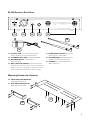
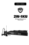
Owner’s Manual
W-1KU
1000 Channel UHF Wireless System
Contents
Introduction.............................................................................................................................. 2
Using this Manual..................................................................................................................... 2
System Features...................................................................................................................... 3
Quick User Controls Guide....................................................................................................... 4
System Operation.................................................................................................................... 8
W-1KU Receiver................................................................................................................... 8
HT-1KU Handheld Microphone Transmitter.........................................................................10
BT-1KU Bodypack Microphone Transmitter........................................................................12
Specifications..........................................................................................................................15
Cautions and Troubleshooting.................................................................................................16
Miscellaneous Tips..................................................................................................................17
Frequency................................................................................................................................18
Accessories.............................................................................................................................18
Service Information.................................................................................................................18
Warranty..................................................................................................................................19
Introduction
Thank you for choosing the Nady W-1KU wireless system, and congratulations on
your choice. The W-1KU has the best performance and price value in professional
UHF wireless, offering clear-channel, frequency-agile operation on the UHF band for
interference-free performance in any application or locale. The W-1KU delivers 1000
user selectable channels, frequency synthesized in 00-09 groups and 00-99 channels in
the US frequency band 672MHz-697MHz. The W-1KU features proprietary companding
and low-noise circuitry for an industry-best 120dB dynamic range, and the clearest,
most natural sound available in wireless today.
Using This Manual
This booklet provides instructions for the operation of the W-1KU and includes a
description of features, a quick user controls guide, a step‑by‑step guide to operations
for each unit, system specifications, a troubleshooting guide, miscellaneous tips,
and servicing information.
2
System Features
W-1KU Receiver
• Unsurpassed state-of-the-art PLL UHF
performance with 120dB dynamic range
and operation up to 500 feet line-of sight
• 1000 user selectable UHF frequencies
per band
• True Diversity circuitry with two complete
front ends for maximizing range and
most effective elimination of dropouts
• Sophisticated IF filtering for simultaneous
operation of HT-1KU or BT-1KU systems
in the same location
• Front panel touch control buttons and
user-friendly LCD configuration menus
• ASC™ (Auto-Sync Channel) IR download
feature sends selected Group/Channel
information to transmitter via IR sender
for easy frequency synchronization
• Front panel backlit LCD display indicates
selected audio output Volume level,
Group, Channel, RF signal strength meter,
A/B Diversity antenna status; Separate
audio LED bar graph display provides
instantaneous audio level status from
a distance
• Back panel Balanced XLR Mic level and
Unbalanced 1⁄4” Line level audio output
jacks, squelch control, RF BNC connectors
for dual removable 1/2 wave antennas,
and DC power input jack
HT-1KU Handheld and
BT‑1KU Bodypack Transmitters
• Choice of transmitters: HT-1KU or BT-1KU,
all with 1000 easily selectable channels:
manually with up/down buttons on units or
via IR Sync download of selected channel
for easy synchronization with receiver
• HT-1KU Handheld transmitter features a
sleek, durable all-metal housing; power
Off/On switch; internal antenna system;
and superior neodymium cartridge for
clear, powerful audio, maximum feedback
rejection, and minimal handling noise
• BT-1KU bodypack transmitter (choice of
three versions: LT, LT/HM, or GT) features
road worthy all-metal case; power Off/
Mute/On switch; flexible external antenna
rod; and mini locking connector for lapel
(LT), Headmic™ (LT/HM), or instrument
(GT) applications
• HT-1KU and BT-1KU transmitters feature
LCD displays indicating selected Group,
Channel, Volume (Input Audio Level), and
Battery level status; transmitting High/Low
RF power switch for optimizing distance
operation depending on application; and
operation with two AA batteries (alkaline
or rechargeable NiMH) for longest reliable,
economical battery life
• Externally powered (adapter included).
• Rugged all-metal housing—optionally
rack mountable (single or dual)
3
Quick User Controls Guide
W-1KU Receiver: Front View
GROUP
1
CHANNEL
VOL
2
8
9
10
11
12
7
3
3
GROUP
CHANNEL
4
5
VOL
1. AF/PEAK LED TREE Shows audio level—the RED
LED indicates maximum audio level allowable
2. LCD DISPLAY For indication of GRP (00-09)/CH
(00-99), Volume Levels (0-63), A-B Diversity,
and RF signal strength indicator 1-6 bars
3. DIVERSITY A/B INDICATORS Indicates A or B
receiver active when transmitter is on
4. FREQUENCY GROUP Indicates selected
frequency group from 00-09
5. FREQUENCY CHANNEL Indicates selected
frequency channel from 00-99
6. OUTPUT VOLUME CONTROL Indicates selected
output volume level range from 00-63
7. RF SIGNAL METER Indicates received signal
strength level from 1-6 bars
8. SET To scroll LCD menu and set the selected
program/function
4
6
9.
UP BUTTON To change the receiver output
VOL level, GRP/CH up by one step at a time
DOWN BUTTON To change the receiver output
VOL level, GRP/CH down by one step at a time
10. IR Infrared LED transmitter window for linking
the RX to the TX for frequency download
11. SYNC BUTTON Press to make the IR link
download the receiver’s selected frequency
to the TX. Positioning the HT-1KU/BT-1KU
transmitters’ IR window 6”-12” away from the
RX IR window, press the SYNC button once
and wait one second for the RX to respond.
If the IR data download is successful the RX
will show all six RF LCD bars and one of the
Diversity antenna icons on the LCD display.
12. POWER BUTTON Press for one second to turn
receiver ON-OFF
W-1KU Receiver: Back View
13
15
16
17
18
19
14
13. DC INPUT JACK For connecting external
AC/DC adapter for powering receiver
14. DC POWER SUPPLY UNIT DC15VDC/400mA
15. BALANCED MIC OUT Audio output—
fixed mic level
16. MUTE (SQUELCH) CONTROL Controls the mute
level for the receiver—turn CCW for maximum
range; turn CW, if needed, to minimize noises
from outside RF interference upon muting
17. UNBALANCED AUDIO OUT Line level
audio output—adjustable
18. RF CONNECTORS A/B Antenna jacks
for RF True Diversity reception
19. ANTENNA 1/2 wave antennas for
A/B connectors
Mounting Rackears for Receiver
20. SINGLE UNIT RACK MOUNT KIT
(Optional) RMK-1KUS
21. DUAL UNIT RACK MOUNT KIT
(Optional) RMT-1KUD
21
20
5
Quick User Controls Guide
HT-1KU Handheld Transmitter
23
24
25
26
37
L
H
RF
22
27
28
29
39
38
IR
40
30
31
32
22. BATTERY COVER Unscrew to insert two
AA alkaline batteries
26. SET To scroll LCD menu and set the
selected program/function
23. MIC BALL Windscreen
27. POWER HI/LOW RF power level setting for
high or low RF output power
24. LCD DISPLAY For indication of GRP (00-09)/CH
(00-99), INPUT AUDIO LEVEL, and BATTERY
status (1 bar=empty). See 37/38/39 in diagram
above for display indicators detail.
25.
6
UP BUTTON To change the VOL level or
GRP/CH settings up by one step at a time
DOWN BUTTON To change the VOL level
or GRP/CH down by one step at a time
28. ON/OFF SWITCH Slide power switch up-down
to turn ON-OFF
29. INTERNAL ANTENNA Built-In antenna
30. IR RECEPTOR SENSOR/WINDOW Infrared LED
sensor for linking the TX to the RX during
IR frequency download.
31. BATTERY COMPARTMENT
32. 2 x AA ALKALINE BATTERIES
Quick User Controls Guide
BT-1KU Bodypack Transmitter (LT, LT/HM or GT)
33
37
38
34
35
39
36
40
43
44
41
42
45
47
46
48
33. INPUT JACK 3.5mm locking mini jack for
connecting audio input cord from lapel mic
(LT), Headmic™ (LT/HM), or instrument (GT)
41. IR RECEPTOR SENSOR Infrared LED sensor for
linking the TX to the RX during IR frequency
download
34. OFF/MUTE/ON Slide power switch to ON or OFF
to turn ON-OFF, set to MUTE to turn power on
with audio muted
42. RF POWER HI/LOW SWITCH To select power
level setting for high or low RF output power
35. ANTENNA Permanently attached antenna
36. LCD DISPLAY For indication of GRP (00-09)/CH
(00-99), INPUT AUDIO LEVEL, and BATTERY
status (1 bar=empty). See 37/38/39 in diagram
above for display indicators detail.
43.
UP BUTTON To change the VOL level or
GRP/CH settings up by one step at a time
DOWN BUTTON To change the VOL level
or GRP/CH down by one step at a time
44. SET BUTTON To scroll LCD menu and set the
selected program/function
37. FREQUENCY GROUP Indicates selected
frequency group from 00-09
45. BATTERY COMPARTMENT
38. FREQUENCY CHANNEL Indicates selected
frequency channel from 00-99
47. 2 x AA ALKALINE BATTERIES
39. INPUT VOLUME METER Indicates input audio
level ranging from 00dB to -30dB
46. LATCHING BATTERY COMPARTMENT DOOR
48. BELT CLIP (on back of unit)—removable clip can
be set for top of transmitter pointing either up
or down
40. BATTERY METER Indicates battery status
(5 bars=full, 1 bar=empty). Change battery
when flashing.
7
System Operation
W-1KU Receiver
Buttons Function
The Power Button (12) is used to turn the
receiver on or off. When the button is
pressed, the lit blue backlight on the
LCD Display (2) indicates the receiver is on.
Press the Power button again to turn off
the receiver. The backlight on the LCD
will turn off indicating the receiver is off.
At power-off the W-1KU receiver will store
the last settings entered and re-display
them at power-on. It can be reprogrammed
to any new Group/Channel, or Volume level.
The default factory setting is Group 08,
Channel 00, and Volume 63.
When the Set Button (8) is repeatedly
pressed the LCD main menu will cycle
in this order:
MAIN MENU > VOLUME > GROUP >
CHANNEL > repeat
The selected function will flash for 20
seconds before returning to the main menu.
The (Up) or (Down) Buttons (9) are
active while in the Set mode, or can be used
to change Volume Level (6) at anytime.
The IR Sync Button (11) is used to transfer
the frequency-selected info from the
receiver to the transmitter being used for
easy synchronization prior to use. Press
the IR Sync Button while the main menu
is displayed, and the IR LED (10) will flash
quickly. This LED indicates IR transmission
is in progress. Press the SET Button
again to stop the flashing or it will halt in
20 seconds automatically.
Selecting the W-1KU Receiver
Volume Level / Group / Channel
See RF Interference and Finding Open
Channels. This section will also aid in finding
desired channel(s) of operation when setting
up your system(s).
8
Press the (Up) or (Down) Buttons once
or the Set button once prior to pressing
or for single stepping through the
Volume Levels (6). Or hold continuously for
faster level selection. Select one of 63 levels
from the Volume menu and advance to Exit
Set Up Mode by pressing the Set Button (8).
Choose the W-1KU operating frequency
by selecting one of ten Groups (4) and one
of 100 Channels (5) that are determined to
be desirable open channels. Press the Set
button twice to skip the volume setting and
enter the Group setup mode, then press
the or buttons once for single stepping
through the groups. Or hold continuously
for faster group selection. Select one of ten
groups available from the Group menu and
then advance to Channel Setup Mode by
pressing the Set button. Or, press the Set
button twice to exit without changing the
channel. Press the or buttons three
times or press the Set button again after
group setting to enter the Channel setup
mode. Press the or buttons once for
single stepping through the channels,
or hold continuously for faster channel
selection. Select one of 100 channels
available from the channel menu or press
the Set button again to exit.
Rack-mounting the Receiver
There are two options available for rack
mounting the W-1KU: single or side-by-side
with another W-1KU receiver.
Single Unit Rack Mount Kit (20): Attach the
optional RMK-1KUS Rack Kit ears to each
side and tighten with supplied screws.
Dual Unit Rack Mount Kit (21): Attach the
optional RMT-1KUD Dual Receiver Rack Tray
to bottom of both receivers and tighten with
supplied screws.
Note: Do not mount the receiver on a rack directly
above an amplifier or other source of high heat.
This could degrade the performance of the
W-1KU. Always ensure adequate airflow and
heat dissipation in any rack configuration.
Installing Antennas
Install antennas by connecting the two
Antennas (19) included with your system to
the two RF Connectors (18) located on the
back of your W-1KU receiver. The optimal
positions of the antennas are 45 degrees
from the receiver and 90 degrees from each
other. For maximum range, it is always best
to maintain a line-of-sight (no obstructions)
between the receiver antennas and the
transmitter at all times whenever possible.
Powering the Receiver
To power the receiver, plug the provided
AC/DC Power Supply (14) adapter into the
DC Input Jack (13) on the back of the receiver,
then plug the adapter into an AC outlet.
Note: Any 15-18VDC source with minimum
400mA capacity can also be used.
Connect either the 1⁄4” Unbalanced Line
Out (17) or XLR Balanced Mic Out (15) to
your mixing board, effect, or amplifier
(see Connecting the Audio Equipment).
To turn on, press the Power Button (12)
for two seconds. The LCD Display (2) will
light (showing Group, Channel, RF Level
Meter, Diversity, and Output Volume). The
5-segment AF LED Tree (1) will display the
received audio level when the transmitter is
activated and audio transmitted. To turn off,
press the Power button for three seconds
and release. The receiver will turn off.
Adjusting the Squelch
The RF Squelch (16) simultaneously controls
both of the A and B True Diversity receiver
mute sections. The control should be
adjusted counterclockwise to the minimum
RF squelch setting at which the RF Level
Meter (7) and the Diversity Indicator (3) will
remain on while your transmitter is in
normal use, up to the maximum operating
range anticipated in use for your application.
However, in areas of high RF activity, the
squelch control may need to be adjusted
clockwise. If the transmitter is off and the
receiver signal and the diversity indicators
are flickering or stay on continuously, the
squelch should be adjusted to a higher
level (clockwise for less mute sensitivity
level) to stop the flickering. Be careful
not to select too high a clockwise setting
as this may reduce the operating range
to below what is needed. A range walk
test will help in selecting the proper level.
If the range is not critical, note that a
clockwise (maximum squelch) setting will
also yield a quieter mute function, which
might be desired in certain applications.
The squelch level is factory preset at
maximum sensitivity and operating range
(i.e. counterclockwise for minimum squelch
level—maximum usable range).
Audio Level and Peak LED Indicator
The W-1KU receiver has a 5-segment
AF Level LED Display (1) that lights up
sequentially, indicating the level of the audio
signal from the transmitter. Occasional
flickering of the top (red) Peak LED on loud
inputs to the transmitter is normal. If the
Peak LED lights continuously decrease
the input audio level to the transmitter
or overload distortion may result.
Connecting the Audio Output
The W-1KU audio output is set up for either
balanced mic (fixed level) or unbalanced line
(adjustable level). The Unbalanced Line Out
is controlled by the or volume control
buttons. The receiver Volume Display (6) will
indicate the level selected. For balanced
output, plug an audio cable with an XLR
connector into the XLR Balanced Mic Out (15)
socket and plug the other end into your
mixing board or amplifier. For unbalanced
output, plug an audio cable with a 1⁄4”
mono (Tip/Sleeve) plug into the Unbalanced
Line Out (17) jack and plug the other end into
your mixing board or amplifier. When using
the BT-1KU instrument transmitter system,
connect the Unbalanced Line Out directly
to your instrument amp or preamp.
9
At maximum receiver volume setting, as
indicated by the Volume display, the system
output is approximately +4dB higher than
a direct cord-to-amp connection.
Note: As when making any connection, make sure
the amplifier or mixing board volume is at the
minimum level before plugging in the receiver
to avoid possible sound system damage.
Your W-1KU receiver is now operational
and ready to use. Once you have
completed the above steps, proceed to
the following instructions for the HT-1KU
Handheld or BT-1KU Instrument
transmitter included with your system.
Note: Only one transmitter can be used with one
receiver. It is not possible to use two transmitters
on the same frequency and mix the output of
these transmitters into one wireless receiver.
HT‑1KU Handheld
Microphone Transmitter
Setting up the Transmitter
The HT-1KU requires two AA size batteries
to operate. To install the batteries onto
the battery compartment, unscrew the
Battery Compartment Cover (22) by turning
counterclockwise until loose and slide down
the cover, exposing the Battery Compartment
(31). Insert two fresh AA batteries according
to the correct polarity as indicated on the
transmitter body. Screw the battery cover
back onto the microphone, making sure
it is securely tightened. Fresh alkaline
batteries can provide up to 8-10 hours of
operation, but in order to ensure optimum
performance it is recommended that the
batteries be replaced after 6-8 hours of
use or as indicated to be necessary by the
flashing Battery (40) icon.
10
Powering the Transmitter On/Off
To turn on the transmitter, slide the power
On/Off Switch (28) to the on position. The LCD
backlight will light up, indicating the unit is
now on. After ten seconds the backlight will
automatically turn off to conserve battery
life. The Group/Channel/Battery (24) indicator
icons stay on for normal operation.
As many of the LCD battery levels should
stay lit as possible, as they indicate usable
battery strength. As the batteries weaken
fewer of the level indicators will stay lit until
only one bar shows, which will then flash
to warn that the batteries are now too low
and should be replaced as soon as possible
with fresh ones.
To preserve battery life, turn the transmitter
off when not in use. To turn the transmitter
off, slide the power on/off switch to the off
position. No LCD or backlight is lit up and
the unit will be off.
Programming the HT-1KU
to the Selected Channel
The transmitter can be programmed to the
same frequency as selected for the receiver,
either via automatic synchronization using
the IR Sync function or manually on the
transmitter itself.
IR Sync Programming:
Use the wireless IR LED Receptor Sensor (30)
to download pre‑programmed channels
from the receiver (see Selecting the W-1KU
Receiver Volume Level/Group/Channel and
Selecting the HT-1KU Transmitter Group and
Channel). Start programming by holding the
IR LED Receptor Sensor about 6”-12” from
the receiver, then press the IR Sync Button
(11) on the receiver. The red IR LED (10) on
the receiver will flash once after one second
indicating IR data transfer, and then once
more at three seconds, indicating that the
IR transmission is over. Upon successful
data transfer (usually in less than two
seconds) the transmitter’s backlight will
light up and the transmitter will transmit
a radio signal on the same channel as the
receiver. The Signal Strength and Diversity
Indicators on the receiver’s LCD display will
then light up, indicating that the IR link is
completed. If no action is taken during the
three seconds of active data transfer, the
receiver and the transmitter units do not link
and transmitter’s previous program channel
remains unchanged.
Note: The IR link is infrared light and thus works
best when this data transfer is accomplished in a
light-shielded or darker environment. It may not
be successful in a brightly lit area. If the transfer
fails, repeat the procedure in a darker location
or somehow shield the link from outside light to
successfully program the transmitter with the
pre-programmed group and channel info from
the receiver.
Manual Programming (GRP/CH and Volume):
The transmitter’s frequency is set using the
Set Button (26) and then the (UP) or (DOWN)
Buttons (25). To start, press the Set button
once. The backlight on the LCD (36) will light
up and the Group Icon (24) will flash. Use the
or buttons to change the group. When a
group selection is finished, press the Set
button again for the channel selection. The
Channel Icon (24) will now flash. Again, use
the or buttons to change the channel as
desired. When the Group/Channel selection
is done, press the Set button to enter the
volume level input setting and then press
or to change in four steps from 0dB to
-30dB (for loudest input) or press the Set
button a second time to exit to the main
menu. To change the volume input level
only, press the Set button three times to
select the volume input level setting. Use
or to change in four steps from 0dB to
-30dB (for loudest input). The level is preset
at -10dB for the HT-1KU, which is best for
most applications.
For normal operation, the transmitter should
have the same Group/Channel as displayed on
the receiver. After programming is finished,
slide the battery cover back then turn the
Mic Ball (23) counterclockwise to secure the
housing. The HT-1KU is now ready for use.
HT-1KU Transmitter Switches
At Power Off the transmitter will store
the last settings entered and re-display
them at the next power on where it can be
reprogrammed to any new Group/Channel.
The default factory setting is Group 08,
Channel 00.
The RF Power Level Switch (27) is used
to select Hi/Low power transmission
(see Operating the HT-1KU Handheld
Transmitter).
Each time the Set Button (19) is pressed,
the LCD main menu will cycle in this order:
MAIN MENU > GROUP > CHANNEL >
VOLUME > repeat
The selected function will flash for 20
seconds before returning to the main menu.
The or Buttons (25) work in the set mode
only. They can be used to change any
Group/Channel as selected (if not using
IR Sync from receiver). They can also be
used to select the desired Input audio level
VOL setting.
Operating the HT-1KU
Handheld Transmitter
During normal operation with the unit
powered on, the transmitter power level
can be changed by sliding the RF Power
Switch (27) to “H” to increase the
transmitted RF power (for longer range)
or to “L” to decrease the RF power
(reduced range). This is a useful feature as
the “L” setting increases battery life and
also optimizes the number of channels
that can be used simultaneously in a given
location. Use this setting for normal use
not requiring maximum operating range.
A range walk test before use will determine
which setting is best for your application.
Slide the On/Off switch to the on position
and the microphone is now ready to use.
The receiver’s RF Signal Meter (7) and
Diversity A or B (3) indicators should now
11
be on, indicating a received signal from
the transmitter. Adjust the volume of the
receiver per Connecting Audio Output.
Note: Avoid acoustic feedback (howling or
screeching) by taking care in selecting PA volume,
transmitter location and speaker placement.
Note: The RF Signal meter and the Diversity A/B
indicator on the receiver’s LCD display should be
“On” in normal operation.
BT-1KU Bodypack Transmitter
(LT, LT/HM or GT)
Setting up the Transmitter
The BT-1KU bodypack requires two AA size
batteries to operate. To install the batteries
into the battery compartment, lift the
Battery Compartment Door (46) by grabbing
the two spring-loaded locking tabs and pull
out, exposing the Battery Compartment (45).
Insert two fresh AA batteries according
to the correct polarity as indicated on the
transmitter body. Close the battery cover,
ensuring the cover is snapped shut. Fresh
alkaline batteries can last provide up to 8-10
hours of operation, but in order to ensure
optimum performance it is recommended
that the batteries be replaced after 6-8 hours
of use or as indicated necessary by the
flashing Battery Meter (40).
Connecting Input Audio Source
Use Audio Input (33) 3.5mm locking mini
jack for connecting the audio input cord
from lapel mic (LT), Headmic™ (LT/HM),
or instrument (GT), depending on which
version transmitter is being used. Secure
the connection to the cable by lining up
the slot of the 3.5mm mini connector
and turning the ring to securely lock in.
12
Powering the Transmitter On/Off
To turn on the transmitter, slide the
Power Off/Mute/On Switch (34) to the Mute
(middle) position (transmitter on, audio
muted). The LCD backlight will light up.
The unit is now on. After ten seconds
the backlight will automatically turn off.
The Group Icon (37) and Battery Meter (40)
remain on in normal operation.
As many of the five LCD battery levels
should stay lit as possible, indicating usable
battery strength. As the batteries weaken,
fewer of the level indicators stay lit until
only one bar shows, which will then flash
to warn that the batteries are now too low
and should be replaced as soon as possible.
To preserve battery life, turn the transmitter
off when not in use. To turn the transmitter
off, slide the Off/Mute/On switch to Mute
and then Off. No LCD or backlight is lit up
and the unit will be off.
Programming the BT-1KU
to the Selected Channel
The transmitter can be programmed to the
same frequency as selected for the receiver,
either via automatic synchronization using
the IR Sync function or manually on the
transmitter itself.
IR Sync Programming:
Use the wireless IR LED Receptor Sensor (41)
to download pre‑programmed channels
from the receiver (see Selecting the W-1KU
Receiver Volume Level/Group/Channel and
Selecting the BT-1KU Transmitter Group and
Channel). Start programming by holding the
IR LED Receptor Sensor about 6”-12” from
the receiver, then press the IR Sync Button (11)
on the receiver. The red IR LED (10) on the
receiver will flash once after one second
indicating IR data transfer, and then once
more at three seconds, indicating that the
IR transmission is over. Upon successful
data transfer (usually in less than two
seconds) the transmitter’s backlight will
light up and the transmitter will transmit
a radio signal on the same channel as the
receiver. The Signal Strength and Diversity
Indicators on the receiver’s LCD display will
then light up, indicating that the IR link is
completed. If no action is taken during the
three seconds of active data transfer, the
receiver and the transmitter units do not link
and transmitter’s previous program channel
remains unchanged.
Note: The IR link is infrared light and thus works
best when this data transfer is accomplished
in a light-shielded or darker environment.
It may not be successful in a brightly lit area.
If the transfer fails, repeat the procedure in
a darker location or somehow shield the link
from outside light to success-fully program
the transmitter with the pre-programmed
group and channel info from the receiver.
Manual Programming (GRP/CH and Volume):
The transmitter’s frequency is set using
the Set Button (44) and then the (UP) or
(DOWN) Buttons (43). To start, press the
Set button once. The backlight on the LCD
(36) will light up and the Group Icon (37) will
flash. Use the or buttons to change
the group. When a group selection is
finished, press the Set button again for the
channel selection. The Channel Icon (38) will
now flash. Again, use the or buttons
to change the channel as desired. When
the group/channel selection is done, press
the Set button to enter volume level input
setting and then press or to change in
four steps from 0dB to -30dB (for loudest
input) or press the Set button a second time
to exit to the main menu. To change volume
input level only, press the Set button three
times to select the volume input level
setting. Use the or to change in four
steps from 0dB to -30dB (for loudest input).
The level is preset at 0dB for GT and -10dB
for LT/HM. These settings are optimal for
most applications.
For normal operation, the transmitter should
have the same Group/Channel as displayed on
the receiver. After programming is finished,
close the battery compartment door,
ensuring that it latches. The BT-1KU is
now ready for use.
BT-1KU Transmitter Switches
At Power Off the transmitter will store
the last settings entered and re-display
them at the next power on where it can be
reprogrammed to any new Group/Channel.
The default factory setting is Group 08,
Channel 00.
The RF Power Level Switch (42) is used
to select Hi/Low power transmission
(see Operating the BT-1KU Handheld
Transmitter).
When the Set Button (44) is pressed, the
LCD main menu will cycle in this order:
MAIN MENU > GROUP > CHANNEL >
VOLUME > repeat
The selected function will flash for 20
seconds before returning to the main menu.
The (UP) or (DOWN) Buttons (43) work
in the set mode only. They can be used to
change any Group/Channel as selected (if
not using IR Sync from receiver). They can
also be used to select the desired Input
audio level VOL setting.
13
Operating the BT-1KU
Bodypack Transmitter
During normal operation with the unit
powered on, the transmitter power level
can be changed by sliding the RF Power
Switch (42) to “H” to increase the
transmitted RF power (for longer range)
or to “L” to decrease the RF power
(reduced range). This is a useful feature as
the “L” setting increases battery life and
also optimizes the number of channels
that can be used simultaneously in a given
location. Use this setting for normal use not
requiring maximum operating range. A range
walk test before use will determine which
setting is best for your application.
The Power Off/Mute/On Switch (34) has
three positions and functions both as a
power on/off and as an audio mute on/
off switch. After the unit is powered on,
slide the power switch to the on position
to un-mute the audio. To mute/un-mute
the audio during use, set the power switch
accordingly. The transmitter is now ready
to use. Slide the On/Off switch to the on
position and the microphone is now ready
to use. The receiver’s RF Signal Meter (7)
and Diversity A/B (3) indicators should now
be on, indicating a received signal from the
transmitter. When ready to transmit audio,
slide the power switch to on to un-mute.
To mute, slide the power switch to Mute
again. Adjust the volume of the receiver
per Connecting Audio Output.
Note: Avoid acoustic feedback (howling or
screeching) by taking care in selecting PA volume,
transmitter location and speaker placement.
Note: The RF Signal meter and the Diversity A/B
indicator on the receiver’s LCD display should be
“On” in normal operation.
14
Instrument Use (BT-1KU/GT only)
Secure the connection of the GT (instrument)
cable by lining up the slot of the 3.5mm
mini connector and turning the ring to
securely lock in. When ready to play, slide
the Power Off/Mute/On switch (26) to ON
position to un-mute the audio. Adjust the
volume on the receiver for one-to-one unity
gain (possible with Input Level set to 0dB
only) with a hardwired cord or select up
to an added 4-5dB boost by adjusting the
receiver volume to maximum for normal
use with guitars and bass guitars.
Note: The audio level should be adjusted on the
instrument as when using a hard-wired cord.
Specifications
SYSTEM OVERALL SPECIFICATIONS
Operating Frequency Range 672MHz-697MHz (US)
Freq. Synthesized
(1000 channels switchable) 25kHz/step
PLL system frequency stability
<0.005%
Frequency Response
30Hz-18kHz +/-3dB
Dynamic Range
120dB
Harmonic Distortion
<0.5%
Modulation
FM (F3E) +/-25kHz normal, +/-75kHz max
Operating Range
150-250 feet typical, 500+feet max line-of-sight
W-1KU RECEIVER SPECIFICATIONS
Receiver System
Dual conversion Super Heterodyne with True Diversity
(two complete receiver sections with optimum audio selected)
Selectivity
60dB, normal +/-75kHz offset
Image Rejection
-70dB, minimum
Sensitivity
-107dBm, normal
Spurious Rejection
65dB, normal
Mute Threshold
- 65dBm to -95dBm (adjustable)
Controls
UP/DOWN selects, SET, IR Sync, Power ON/OFF buttons,
MUTE level control
LCD Display
Single backlight LCD panel indicating selected Group/Channel, received
RF levels, A/B diversity, and unbalanced receiver out Volume levels
LED Display 5-segment LED tree indicating received audio levels from transmitter
Audio Output Level
Unbalanced output: 360mV adjustable audio output @ +/- 25 KHz deviation
Balanced output: 24mV fixed level audio output @ +/- 25 KHz deviation
Output Impedance
Balanced and unbalanced: 600 Ω
Power Requirement
15VDC/0.4A
Antennas
Dual BNC right angle
Dimensions
8.25”W x 6.25”D x 1.75”H (21.6cm x 15.9cm x 4.5cm)
Weight 2 lbs (0.907 Kg)
Housing Construction Metal
HT-1KU HANDHELD TRANSMITTER SPECIFICATIONS
RF Output Power
HI/LOW selectable
HI: +14dBm (25mW typical), LOW: +4dBm (2.5mW typical)
Harmonic and Spurious Emission -50dBc normal
Audio Input Levels
24mV for +/- 25 KHz deviation
Impedance
6.0 kΩ
Controls
Power ON/OFF, RF Power HI/LOW switches, Set/Up/Down
LCD Display
Group/Channels/Volume/Battery Levels
Antenna Type
Integral
Battery Type
2 x AA alkaline batteries operation
Battery Life
8-10 hours typical
Dimensions
10”L x 2”D (25.4 cm x 5.1 cm)
Weight (w/o batteries)
11 oz (0.312 kg)
Housing Construction Metal
BT-1KU BODYPACK TRANSMITTER SPECIFICATIONS
RF Output Power
Hi/Lo selectable
HI: +14dBm (25mW typical), LOW: +4dBm (2.5mW typical)
Harmonic and Spurious Emission -50dBc normal
Audio Input Levels
75mV (Lapel/Lavaliere—LT ) / 310mV (Headmic™—LT/HM) /
225mV (Instrument—GT) for +/- 25KHz deviation)
Input Impedance
500 kΩ (Instr.)
Controls
Power OFF/MUTE/ON, RF Power HI/LOW switches, Set/Up/Down
Input Connector Mini 3.5mm with locking nut
LCD Display
Group/Channels/Volume/Battery Levels
Antenna Type
External fixed
Battery Type
2 x AA alkaline batteries operation
Battery Life
8-10 Hours typical
Dimensions
2.5”W x 3.25”H x 1-13/16”D (6.35cm x 8.3cm x 1.82cm)
Weight (w/o batteries)
3.8 oz (0.108 kg)
Housing Construction Metal
Specifications subject to change at any time without prior notice for purposes of product improvement
15
Cautions and Troubleshooting
Feedback
Avoid acoustic feedback (howling or
screeching) by taking care in selecting
PA volume, transmitter location and
speaker placement.
Please also note the pickup pattern
characteristics of the microphone selected.
Unidirectional mics are more resistant to
feedback. However, they pick up sound
sources best that are directly in front of the
mic. Also mics that are farther from the
sound source require more acoustic gain
and thus are also more prone to feed back
than close-source mics such as handheld.
No or Low Audio
If you are not getting audio through the
system, carefully re-check all setups.
Especially note that the receiver and
transmitter must be set to operate on the
same RF channel. For BT-1KU Bodypack
transmitter, also confirm that the Power
Off/Mute/On Switch (34) is not in the Mute
position. The receiver’s Unbalanced Line
Level Out (17) is adjustable so make sure
the Volume (6) is set properly.
RF Interference and
Finding Open Channels
If you encounter slight receiving interference
when the transmitter is far from the receiver
(from other than an operating TV station
on the same frequency), often it can be
overcome by adjusting the receiver‘s
Squelch Control (16) (see Adjusting the
Squelch). If receiving interference on a
selected channel with the transmitter
off, you must reprogram the receiver
and transmitter to a different channel.
See: Selecting the W-1KU Receiver Volume
Level / Group / Channel
Selecting the HT-1KU/BT-1KU Transmitter
Group and Channel
16
Programming the HT-1KU/BT-1KU
to the Selected Channel
Programming the HT-1KU/BT-1KU with the
Group/Channel Selected on the Receiver
To reprogram, you must first find an open
channel. To do this, follow the operating
procedure outlined in Selecting the W-1KU
Receiver Volume Level / Group / Channel.
With the associated transmitter off, scroll
through the groups/channels to find one that
shows no received signal on the receiver’s
RF Signal Meter (7) (no bars). Also, there
must be no bars either on each of the
three immediately adjacent channels both
above and below the selected channel
for optimum interference-free operation
(i.e. in a field of seven adjacent channel
total—with the channel used in the middle).
If operating multiple W-1KU Series systems
simultaneously, repeat this procedure
with every new channel being selected,
with previously tuned systems all on,
both transmitters and receivers.
Please note that wireless frequencies are
shared with other radio services. According
to FCC regulations, wireless microphone
operations are unprotected from
interference from other licensed operations
in the band. If any interference is received
by any Government or non-government
operation, the wireless microphone must
cease operation or change frequencies.
The above statement is valid only for use
in the U.S.A.
Note: More bars in the Received Signal (39) icon
indicate good signal strength in operation with the
transmitter on, but more than 1 bar showing with
the transmitter off also indicates the presence of
likely RF interfering signals at that location. If this
happens, select a different GRP/CH. One bar or
less is ideal for interference-free operation.
Miscellaneous Tips
• For optimum operation with external
antennas, low loss RF shielded cable
should be used and the length of the
cable should not exceed 10’ (3 m).
• The receiver antennas should be kept
away from any metal surfaces whenever
possible as they can reflect away or
shield the incoming RF signal.
• If the receiver’s volume control is set
too high, it may overdrive the input
of the attached audio mixer, causing
distortion. Conversely, if the output is set
too low, the overall signal-to-noise ratio
of the system may be reduced, causing
noticeable hiss. If such noise occurs,
adjust the output level of the receiver
so that highest sound pressure level
going into the microphone transmitter
causes no input overload in the mixer, but
permits the mixer level control to operate
in the normal range (not too high and
not too low). This provides the optimum
signal-to-noise for the entire system.
• Before inserting the batteries, ensure that
they are inserted with the correct polarity.
• Before operation, confirm that the
receiver and associated transmitter are
tuned to the same frequency group and
channel number.
• After making a receiver channel change,
ensure that the corresponding change is
also made on the matching transmitter.
• Use only brand new alkaline batteries.
Do not use “general purpose” carbon
batteries. When batteries are weak,
replace all the batteries at the same time.
Do not mix new and old batteries.
• Position the receiver so that it has the least
possible obstructions between it and the
transmitter. Line-of-sight is best!
• For the best operation, the receiver
should be placed at least 3’ (1 m) above
the ground and 3’ (1 m) away from a wall
or metal surface. The transmitter should
also be at least 3’ (1 m) from the receiver.
Keep antennas away from noise sources
such as motors, automobiles, neon lights,
signal processors, computers, as well as
large metal objects.
• A receiver cannot receive signals from
two or more transmitters simultaneously.
• Turn the transmitter off when it is not
in use. For longest life, remove the
batteries if the unit is not to be used for
a long period as the transmitters draw
a tiny residual current to maintain the
programmed settings, even when turned
off. Also, since batteries installed for a
long time can sometimes corrode and/or
leak, causing damage, it is generally
recommended that batteries be removed
whenever the transmitters are not
being used.
• When using the BT-1KU bodypack for
instrument use: Scratchy noises can
sometimes occur when an electric guitar
with dirty pots or connections is used with
a wireless system. Therefore, the supplied
capacitor provides first-order filtering of
the RF signal from the cord into the guitar
and eliminates virtually all scratchy noises.
Should your equipment still produce
scratchy noise, we suggest these steps to
eliminate problems:
1) Make sure all guitar volume and tone
pots are clean and all contacts are solid.
This is very important.
2) Solder a 47pF capacitor across the pot
to ground terminal of the guitar’s volume
and tone pots to provide extra filtering.
• During operation, the transmitter and the
receiver should be as close as possible for
optimum results but never closer than 3’
(1 m) as that may overload the receiver’s
input circuitry and cause noises.
17
Frequency
Frequency Plan
Band 1: 672.000-696.975MHz
25KHz per step (1000 Channels) U.S.
Accessories
Part Number
Description
IC-U1K Instrument cable included for BT-1KU/GT transmitter,
3.5mm locking mini plug to 1⁄4”
AC-W1KU
15-18VDC/400mA AC/DC receiver power supply adapter included
RMK-1KUS
Single receiver rack mount kit (optional)
RMT-1KUD
Dual (side-by-side) receiver rack mount tray kit (optional)
Service Information
In the U.S. If you are experiencing operational problems with your system, please refer to
the Support page at www.nady.com for assistance. Should your wireless system require
service, please contact the Nady Service Department at (510) 652-2411 for a Return
Authorization (R/A) Number and service quote (if out of warranty). Make sure the R/A
Number is clearly marked on the outside of the package that you are returning.
If your unit is out of warranty, please enclose a cashier’s check or money order (or pay
by credit card) per instructions by the Nady Service Department. Ship your unit prepaid
to: Nady Systems, Service Department, 6701 Shellmound Street, Emeryville, CA 94608.
Include a brief description of the problem you are experiencing. For service of a unit under
warranty, please follow the instructions in the following section.
Outside the U.S For service and warranty matters please contact the Nady distributor in your
country through the dealer/store from which you purchased this product.
Do not attempt to service this unit yourself as
it can be dangerous and will also void the warranty.
18
One Year Limited Warranty
Nady Systems, Inc. warrants to the original consumer purchaser that the unit is free from any defects
in material or workmanship for a period of one year from the date of original retail purchase. If any such
defect is discovered within the warranty period, Nady Systems, Inc. will repair or replace the unit free of
charge, subject to verification of the defect or malfunction upon return to Nady Systems. Please do not
return your Nady product to the store where it was purchased as Nady Systems handles your warranty
service directly. Communication with our Service Department is the most efficient means of servicing
your unit and we are dedicated to keeping you a satisfied customer.
To the extent permitted by law, any applicable implied warranties, including warranties of merchantability
and fitness are hereby limited to one year from the date of purchase. Consequential or incidental
damages resulting from a breach of any applicable express or implied warranties are hereby excluded.
This warranty is in lieu of all other agreements and warranties, general or special, express or implied
and no representative or person including a Nady dealer, agent, or employee is authorized to assume
for us any other liability in connection with the sale or use of this Nady Systems’ product.
Whereas some states do not allow limitations on how long implied warranties last, and do not allow
exclusion of incidental or consequential damages, the above limitations and exclusions may not apply
to you. This warranty gives you specific legal rights and you may also have other rights which may vary
from state to state.
This warranty is subject to the following conditions:
1) This system must have been purchased from an authorized Nady dealer and all warranty
service must be performed by Nady’s service department. Any service not performed by Nady
will automatically void this warranty.
2) Items not covered: physical damage resulting from improper handling of the unit in transit from the
factory by the shipper (Nady Systems is not responsible for such damage and all such claims must be
made against the shipping company by the consignee); defects caused by normal wear of the product
(expendable parts are typically connectors, cables, potentiometers, switches and similar components);
damage or defects caused by abuse, neglect, accident, failure to connect or operate the unit in any way
that does not comply with applicable technical or safety regulations, or improper repair, excessive heat
or humidity, alteration or unreasonable use of the unit, causing cracks, broken cases/housings or parts;
damage caused by leaking batteries; finish or appearance items; items damaged in shipment en route to
Nady Systems, Inc. for repair. The warranty is null and void if any Nady serial number has been removed
or defaced.
How To Obtain Service:
1) If factory service is required, you must contact our Service Department at (510) 652-2411 for a return
authorization (RA) number. Make sure the RA number is clearly marked on the outside of your package.
(Please note: if an RA number is not included, our shipping department cannot accept your package.)
2) Send the unit back to Nady Systems, 6701 Shellmound Street, Emeryville, CA, 94608, freight pre-paid.
You must include proof of date and place of purchase (i.e., photocopy of your bill of sale) or Nady cannot
be responsible for repair or replacement. Nady Systems, Inc. will not repair, nor be held responsible,
for any units returned without proper identification, return address, and RA number clearly marked
on the package.
3) Per the above, Nady will perform all warranty service and return the unit to you at no charge.
Nady Systems will inform the buyer if product sent in does not meet the terms of this warranty
and will provide a quote for fixing the unit and/or shipping it back exclusively at the buyer’s expense.
19
6701 Shellmound Street | Emeryville, CA USA 94608
T 510.652.2411 | F 510.652.5075 | www.nady.com