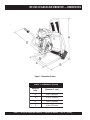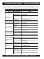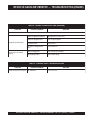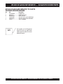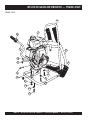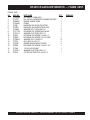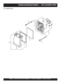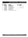
1
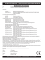
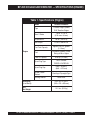
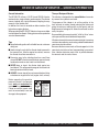
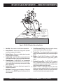
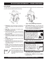
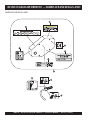
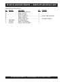
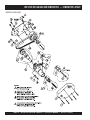
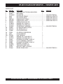
OPERATION AND PARTS MANUAL
MULTIQUIP/STOW
MODEL: BP-25H CE
GASOLINE BACKPACK
VIBRATOR
(Honda Gasoline Engine)
Revision #4 (12/19/07)
THIS MANUAL MUST ACCOMPANY
THE EQUIPMENT AT ALL TIMES.
BP-25H CE GASOLINE VIBRATOR — SILICOSIS/RESPIRATORY WARNINGS
PAGE 2 — BP-25H CE GASOLINE VIBRATOR — OPERATION MANUAL — REV. #4 (12/19/07)
BP-25H CE GASOLINE VIBRATOR — TABLE OF CONTENTS
Multiquip BP-25H CE
Honda GXH50QXA Engine
Concrete Gasoline Vibrator
Air Cleaner Assembly......................................... 36-37
Camshaft Assembly ........................................... 38-39
Carburetor Assembly ......................................... 40-41
Control Assembly ............................................... 42-43
Crankcase Cover Assembly ............................... 44-45
Crankshaft/Balancer Assembly .......................... 46-47
Cylinder Barrel Assembly ................................... 48-49
Fan Cover Assembly .......................................... 50-51
Fly Wheel and Ignition Coil Assembly ................ 52-53
Fuel Tank Assembly ........................................... 54-55
Oil Case Assembly ............................................. 56-57
Piston and Connecting Rod Assembly ............... 58-59
Recoil Starter Assembly..................................... 60-61
Tools (Spark Plug) ............................................. 62-63
Labels Assembly ................................................ 64-65
Silicosis/Respiratory Warnings .................................. 2
Table of Contents ...................................................... 3
Specifications (Noise and Vibration) ......................... 4
Specifications (Engine) ............................................. 5
Dimensions ............................................................... 6
Safety Message Alert Symbols .............................. 7-8
Rules For Safe Operation .................................... 9-10
General Information .................................................11
Vibrator Components ...............................................12
Engine Components ................................................13
Pre-Inspection (Engine) ...........................................14
Head and Shaft Selections ......................................15
Head and Shaft Connections ............................. 16-17
Protective Sleeve Installation ...................................18
Initial Start-up (Engine) ............................................19
Operation .................................................................20 Terms and Conditions of Sale ..................................66
Engine Shutdown .....................................................21
Maintenance (Engine)........................................ 22-24
Preparation for Long-Term Storage .........................25
Troubleshooting (Engine) ................................... 26-27
Explanation of Code in Remarks .............................28
Suggested Spare Parts ............................................29
Component Drawing
Nameplate and Decals....................................... 30-31
Vibrator Assembly .............................................. 32-33
Frame Assembly ................................................ 34-35
NOTE
Specification and part
number are subject to
change without notice.
BP-25H CE GASOLINE VIBRATOR — OPERATION MANUAL— REV. #4 (12/19/07) — PAGE 3
BP-25H GAS VIBRATOR — SPECIFICATIONS (NOISE AND VIBRATION)
EC Declaration of Conformity
We
of
Multiquip (UK) Ltd.
Hanover Mil, Fitzroy Street, Ashton Under Lyne, UK, OL7 0TL
declare that:
Equipment
Model Name/SN#
Backpack Concrete Vibrator (Poker)
BP25H (S/N’s X164600, X164602, X164603, X164605, X164606, X164607, X164608,X164609,
W460637 and W460645)
In accordance with the following Directive(s):
98/37/EC
98/37/EC
The Machinery Directive
Electromagnetic Compatability
Has been designed and manufactured to the following specifications:
BS EN 292-1:1991
Safety of Machinery- Basic Concepts
BS EN 292-2:1991
Safety of Machinery- Basic Concepts
BS EN 13478:2002
Safety of Machinery- Fire Prevention and Protection
BS EN 294:1992 Safety of Machinery- Safety Distances to Prevent Danger Zones Being Reached
By Upper Limbs.
BS EN 563:1994 Safety of Machinery- Temperature of Touchable Surfaces
BS EN 953:1998 Safety of Machinery- Guards
BS CISPR 12:1997
Vehicles- Motor Boats and Spark-Ignited Engine Driven Devices
prEN 12649-2001
Vehicles- Concrete Compactors and Smoothing Machines — Safety
BS EN 61310-1:1995
Safety of Machinery- Indication, Marking and Actuation Requirements for Visual,
Auditory and Tactile Signals.
BS EN 61310-2:1995
Safety of Machinery- Indication, Marking and Actuation Requirements for Visual,
Auditory and Tactile Signals.
BS EN 61310-3:1995
Safety of Machinery- Indication, Marking and Actuation Requirements for Visual,
Auditory and Tactile Signals.
BS EN 60417-2:1999
Safety of Machinery- Indication, Marking and Actuation Requirements for Visual,
Auditory and Tactile Signals.
Noise measurements have been made in accordance with BS EN ISO 3744:1995 with internal control of production (Schedule 8/
Annex V). The declared noise values are as follows:
Noise Emissions Measured1 — Sound Pressure Level LPA = 92 db (A)
Noise Emissions Measured — Sound Power Level LWA = 107 db (A)
Vibration Measured2 — The weighted RMS acceleration value to which the body is subjected does not exceed 0.5m/s2
Current HSE guidelines based on an 8-hour energy equivalent frequency weighted vibration total value, A(8) of 2.5 m/s²,
indicate that it would be acceptable to use the unit for a maximum of 53 minutes in an eight hour day.
1. C weighted instantaneous sound pressure value at work stations does not exceed 63 Pa (130 db in relation 20µPa).
2. The hand-Arm Vibration (HAV) value ahv, on the vibrator is 7.54 m/s2
I hereby declare that the equipment named above has been designed to comply with the relevant sections of the above referenced
specifications. The unit complies with all essential requirements of the Directives.
Signed by: ................................................................................................................
Name:
Position
L. Whitelegg
Director of Operations
Done at
Ashton-Under-Lyne
On
October 31, 2003
PAGE 4 — BP-25H CE GASOLINE VIBRATOR — OPERATION MANUAL — REV. #4 (12/19/07)
BP-25H CE GASOLINE VIBRATOR — SPECIFICATIONS (ENGINE)
Table 1. Specifications (Engine)
Model
HONDA GXH50QXA
Type
4 stroke, Single Cylinder,
OHV, Gasoline Engine
Bore X Stroke
1.65 in. x 1.42 in.
(41.8 mm x 36 mm)
Displacement
49 cm3 (3.0 cu-in)
Max Output
2.5 H.P./7,000 R.P.M.
Fuel Tank Capacity
Approx. 0.32 U.S. gallons
(1.2 liters)
Fuel
Unleaded Gasoline Octane
Rating of 86 or Higher
Engine
Lube Oil Capacity
0.26 qts (.25 liters)
Spark Plug Type
NKG: CR5HSB
DENSO: U16FSR-UB
Spark Plug Gap
0.024 ~ 0.028 in.
(0.60 ~ 0.70 mm)
Speed Control
Method
Centrifugal Fly-weight Type
Star ting Method
Recoil Star t
Dimension
(L x W x H)
8.9 x 10.8 x 13.9 in.
(225 x 274 x 353 mm)
Dry
Net Weight
12.1 lbs (5.5 Kg.)
BP-25H CE GASOLINE VIBRATOR — OPERATION MANUAL— REV. #4 (12/19/07) — PAGE 5
BP-25H CE GASOLINE VIBRATOR — DIMENSIONS
Figure 1. Dimensions (Frame)
TABLE 2. Dimensions (Frame)
Reference
Letter
Dimension ft. (mm.)
A
23.0 in. (584 mm.)
B
13.75 in. (349 mm.)
C
13.0 in. (330 mm.)
D
21.0 in. (533 mm.)
PAGE 6 — BP-25H CE GASOLINE VIBRATOR — OPERATION MANUAL — REV. #4 (12/19/07)
BP-25H CE GASOLINE VIBRATOR — SAFETY MESSAGE ALERT SYMBOLS
FOR YOUR SAFETY AND THE SAFETY OF OTHERS!
Safety precautions should be followed at all times when operating
this equipment. Failure to read and understand the Safety
Messages and Operating Instructions could result in injury to
yourself and others.
This Owner's Manual has been
developed to provide complete
instructions for the safe and efficient
operation of the Multiquip Model BP25H CE Gasoline Backpack
Vibrator. Refer to the engine
manufacturer’s instructions for data
relative to its safe operation.
Before using this vibrator, ensure
that the operating individual has
read and understood all
instructions in this manual.
NOTE
HAZARD SYMBOLS
Potential hazards associated with the operation of this
equipment will be referenced with "Hazard Symbols" which
appear throughout this manual, and will be referenced in
conjunction with Safety "Message Alert Symbols".
WARNING - LETHAL EXHAUST GASES
Gasoline engine exhaust gases contain
poisonous carbon monoxide. This gas is
colorless and odorless, and can cause
DEATH if inhaled. NEVER operate this
equipment in a confined area or enclosed structure that
does not provide ample free flow air.
WARNING - EXPLOSIVE FUEL
SAFETY MESSAGE ALERT SYMBOLS
The three (3) Safety Messages shown below will inform you
about potential hazards that could injure you or others. The
Safety Messages specifically address the level of exposure to
the operator, and are preceded by one of three words: DANGER,
WARNING, or CAUTION.
DANGER
You WILL be KILLED or SERIOUSLY injured if you
do not follow directions.
Gasoline is extremely flammable, and
its vapors can cause an explosion if
ignited. DO NOT start the engine near
spilled fuel or combustible fluids.
DO NOT fill the fuel tank while the engine
is running or hot.
DO NOT overfill tank, since spilled fuel could ignite if it
comes into contact with hot engine parts or sparks from
the ignition system. Store fuel in approved containers, in
well-ventilated areas and away from sparks and flames.
NEVER use fuel as a cleaning agent.
WARNING - BURN HAZARDS
WARNING
You COULD be KILLED or SERIOUSLY injured if
you do not follow directions.
CAUTION
Engine components can generate extreme
heat. To prevent burns, DO NOT touch these
areas while the engine is running or
immediately after operations. NEVER
operate the engine with heat shields or heat
guards removed.
You CAN be injured if you do not follow directions
BP-25H CE GASOLINE VIBRATOR — OPERATION MANUAL— REV. #4 (12/19/07) — PAGE 7
BP-25H CE GASOLINE VIBRATOR — SAFETY MESSAGE ALERT SYMBOLS
WARNING - ROTATING PARTS
NEVER operate equipment with covers,
or guards removed. Keep fingers, hands,
hair and clothing away from all moving
parts to prevent injury.
CAUTION - ACCIDENTAL STARTING
ALWAYS place the engine ON/OFF
switch in the OFF position when the
vibrator is not in use.
CAUTION - OVER-SPEED CONDITIONS
NEVER tamper with the factory settings
of the engine governor or settings.
Personal injury and damage to the engine
or equipment can result if operating in
speed ranges above maximum allowable.
NOTE
CAUTION - RESPIRATORY HAZARDS
ALWAYS wear approved respiratory
protection.
CAUTION - SIGHT AND HEARING HAZARDS
ALWAYS wear approved eye and
hearing protection.
CAUTION - EQUIPMENT DAMAGE MESSAGES
Other important messages are provided throughout this
manual to help prevent damage to your vibrator, other
property, or the surrounding environment.
This vibrator, other property, or
the surrounding environment
could be damaged if you do not
follow instructions.
PAGE 8 — BP-25H CE GASOLINE VIBRATOR — OPERATION MANUAL — REV. #4 (12/19/07)
BP-25H CE GASOLINE VIBRATOR — RULES FOR SAFE OPERATION
DANGER - READ THIS MANUAL!
Failure to follow instructions in this manual may lead to
serious injury or even DEATH! This equipment is to be
operated by trained and qualified personnel only! This
equipment is for industrial use only.
The following safety guidelines should always be used when
operating the vibrator.
GENERAL SAFETY
■ DO NOT operate or service this equipment
before reading this entire manual.
■ This equipment should not be operated by persons under 18
years of age.
■ NEVER operate this equipment when not
feeling well due to fatigue, illness or taking
medicine.
■ NEVER operate this equipment under the influence or drugs or
alcohol.
■ Whenever necessary, replace nameplate, operation and safety
decals when they become difficult read.
■ ALWAYS check the machine for loosened threads or bolts
before starting.
■ Dress properly. Wear appropriate clothing and protective safety
equipment. Wear clothing that will not likely become caught
in the equipment or snag on the forms. Eye, hand, hearing,
and foot safety equipment is required.
■ NEVER touch the hot exhaust manifold,
muffler or cylinder. Allow these parts to
cool before servicing engine.
■ High Temperatures – Allow the engine to cool before adding
fuel or performing service and maintenance functions. Contact
with hot! components can cause serious burns.
■ The engine of this vibrator requires an adequate free flow of
cooling air. NEVER! operate the vibrator in any enclosed or
narrow area where free flow
of the air is restricted. If the
air flow is restricted it will
cause serious damage to the
vibrator or engine and may
cause injury to people and
property. Remember the
engine gives off DEADLY
gases.
■ ALWAYS refuel in a well-ventilated area, away from sparks
and open flames.
■ ALWAYS use extreme caution when
working with flammable liquids. When
refueling, stop the engine and allow it
to cool. DO NOT smoke around or near
the machine. Fire or explosion could
result from fuel vapors, or if fuel is spilled
on a hot engine.
■ NEVER operate the equipment in an explosive atmosphere
or near combustible materials. An explosion or fire could result
causing severe bodily harm or even death.
■ Topping-off to filler port is dangerous, as it tends to spill fuel.
■ Refer to the Engine Owner's Manual for engine technical
questions or information.
■ NEVER use accessories or attachments, which are not
recommended by Multiquip for this equipment. Damage to
the equipment and/or injury to user may result.
■ Manufacturers do not assume responsibility for any accident
due to equipment modifications.
BP-25H CE GASOLINE VIBRATOR — OPERATION MANUAL— REV. #4 (12/19/07) — PAGE 9
BP-25H CE GASOLINE VIBRATOR — RULES FOR SAFE OPERATION
■ NEVER run engine without air cleaner. Severe engine damage
may occur.
■ ALWAYS read, understand, and follow procedures in
Operator’s Manual before attempting to operate equipment.
■ ALWAYS be sure the operator is familiar with proper safety
precautions and operating techniques before using vibrator.
■ ALWAYS store equipment properly when it is not being used.
Equipment should be stored in a clean, dry location out of the
reach of children.
■ NEVER leave the vibrator unattended, turn off engine when
unattended.
■ Unauthorized equipment modifications will void all
warranties.
■ NEVER use vibrator near flammable or low flash point fluids.
These fluids could ignite or explode.
■ ALWAYS become familiar with the components of the vibrator
before operating.
■ ALWAYS replace nameplate, operation and safety decals
when they become difficult to read.
■ NEVER operate vibrator around corrosive chemicals or water
containing toxic substances. These fluids could create serious
health and environmental hazards. Contact local authorities
for assistance.
■ NEVER use accessories or attachments which are not
recommended by the manufacturer for this equipment.
Damage to the equipment and/or injury to user may result.
Maintenance Safety:
■ NEVER lubricate components or attempt service on a
running machine.
■ ALWAYS allow the vibrator a proper amount time to cool
before servicing.
■ Keep the machinery in proper running condition.
■ Fix damage to the machine immediately and always replace
broken parts.
■ Dispose of hazardous waste properly. Examples of
potentially hazardous waste are used motor oil, fuel and
fuel filters.
■ DO NOT use food or plastic containers to dispose of
hazardous waste.
■ DO NOT pour waste, oil or fuel directly onto the ground,
down a drain or into any water source.
TRANSPORTING
■ ALWAYS shutdown engine before transporting.
■ Tighten fuel tank cap securely and close fuel cock to prevent
fuel from spilling.
■ ALWAYS use proper lifting techniques when using or moving
the vibrator motor (backpack), flexible shaft, or vibrator head
assembly.
EMERGENCIES
■ ALWAYS know the location of the
■ Manufacturer does not assume responsibility for any accident
nearest fire extinguisher.
due to equipment modifications. Unauthorized equipment ■ ALWAYS know the location of the
modification will void all warranties. Any modification which
nearest first aid kit.
could lead to a change in the original characteristics of the
■ In emergencies always know the location of the
machine should be made only by the manufacturer who shall
nearest phone or keep a phone on the job site.
confirm that the machine is in conformity with appropriate
Also know the phone numbers of the nearest
safety regulations.
ambulance, doctor and fire department. This
■ ALWAYS observe all applicable compulsory regulations
information will be invaluable in case of an
relevant to environmental protection, especially, fuel storage,
emergency.
the handling of hazardous substances, and the wearing of
protective clothing and equipment. Instruct the user as
necessary, or, as the user, request this information and training.
1
2 3
4
5 6
7
8 9
*
0 #
FIRE
DEPARTMENT
■ NEVER disconnect any "emergency or safety devices".
These devices are intended for operator safety. Disconnection
of these devices can cause severe injury, bodily harm or even
death! Disconnection of any of these devices will void all
warranties.
PAGE 10 — BP-25H CE GASOLINE VIBRATOR — OPERATION MANUAL — REV. #4 (12/19/07)
BP-25H CE GASOLINE VIBRATOR — GENERAL INFORMATION
General Information
The BP-25H CE utilizes a 2.5 HP Honda GXH50 4-stroke,
overhead valve, single cylinder, gasoline engine. The vibrator
comes standard with a quick-disconnect coupling for easy
removal of the flexible shaft.
In addition, the frame is mounted on rubber isolators (3) to
help reduce engine vibration.
When operating the BP-25H CE Vibrator, always wear rubber
insulated gloves and boots. Safety glasses and ear protection
are also recommended.
Tips
■ Keep the bending radius of the flexible hose to a minimum
during use.
■ Avoid starting the unit with the vibrator head immersed in
the concrete mix. After the engine has started, immerse
the vibrator head into concrete mix.
■ Excessive wear to the vibrating head can result from
misuse. DO NOT allow the head to vibrate against already
hardened concrete or steel used in reinforcement.
■ NEVER drop or knock the vibrator head against any
hard objects. This will prevent damage to the eccentric or
bearings contain within the head.
■ ALWAYS rinse or wipe off any wet concrete before it dries
or hardens on any part of the unit (engine, shaft, or head).
Before operating this gasoline
powered vibrator, the operator
must read and understand the
contents of the operation manual.
Failure to read this manual could
result in severe bodily harm and
damage to the equipment.
Theory of Backpack Vibrator
The vibrator is designed for the consolidation of concrete
by removal of air pockets and voids.
The purpose of this vibrator is to set the particles in the
fresh concrete in motion, thereby reducing the friction and
giving the mixture a mobile quality so that gravity and the
displacement of entrapped air allows the concrete to settle
easily into place.
By consolidating the concrete quickly, "stiffer" or "drier" mixes
can be poured than would otherwise be possible.
Vibration also make the concrete more watertight, increasing
resistance to weathering, and creating a better bond between
concrete and reinforcement.
Because vibration causes much of the entrapped air in the
concrete to rise to the surface, honeycombing is prevented.
Also, vibration eliminates most of the air pockets between
the concrete and the vertical forms.
WARNING
To avoid injury,
you MUST read
and understand
operator’s manual
before using this
machine.
This machine to
be operated by
qualified
personnel only.
Ask for training
as needed.
P/N 35137
BP-25H CE GASOLINE VIBRATOR — OPERATION MANUAL— REV. #4 (12/19/07) — PAGE 11
BP-25H CE GASOLINE VIBRATOR — VIBRATOR COMPONENTS
Figure 3. BP-25H CE Gasoline Vibrator Application
1.
Hard Hat – Always wear a hard hat for head protection.
8.
2.
Safety Glasses – Always wear safety glasses to protect
eyes from foreign matter and debris.
Quick Disconnect Fitting – Allows for the quick and easy
removal of the flexible shaft from the vibrator.
9.
Throttle Grip – Turn clockwise (rabbit) to increase engine
speed, turn counterclockwise (turtle) to decrease engine
speed.
3.
Rubber Gloves – Always wear rubber gloves to protect
hands from abrasive materials.
4.
Felixible Shaft – The BP-25H CE can accommodate various
shaft lengths. See Tables 4 and 5 for shaft length dimensions.
5.
Vibrating Head – The BP-25H CE can accommodate
various vibrating heads. See Table 6 for various head types.
Typical applications include large retaining walls, bridge
decks, and columns.
6.
Rubber Boots – Always wear rubber boots to protect feet
from abrasive materials.
7.
Belt Guard – Prevents access to the pulleys or V-belt while
vibrator is running. DO NOT operate the vibrator with this
cover removed.
10. Engine – The BP-25H CE utilizes a 2.5 HP Honda
GXH50, 4-stroke, overhead valve, single cylinder, gasoline
engine.
11. Backpack Harness/Pad – The BP-25H CE is equipped
with an adjustable harness. Adjust the harness to a
comfortable fit so that it will not slip or fall. In addition a back
pad has been added for operator comfort.
12. Frame – Made of a lightweight metal alloy, this frame
features an engine support platform that can be rotated
360 degrees. In addition, the frame has three rubber shock
mounts installed to help reduce engine vibration.
PAGE 12 — BP-25H CE GASOLINE VIBRATOR — OPERATION MANUAL — REV. #4 (12/19/07)
BP-25H CE GASOLINE VIBRATOR — ENGINE COMPONENTS
INITIAL SERVICING
The engine (Figure 4) must be checked for proper lubrication and filled with fuel prior to operation. Refer to the manufacturer’s engine
manual for instructions and details of operation and servicing.
Figure 4. Honda GXH50 Engine Components
1. Choke Lever – Used in the starting of a cold engine, or 8. Fuel Tank/Fuel Filler Cap – Fuel tanks holds 0.32
in cold weather conditions. The choke enriches the fuel
gallons (1.2 liters) of unleaded gasoline. Remove fuel
mixture.
filler cap to add unleaded gasoline to the fuel tank. Make
sure cap is tightened securely. DO NOT over fill.
2. Spark Plug – Provides spark to the ignition system.
Clean spark plug once a week.
DANGER - EXPLOSIVE FUEL HAZARD
3. Recoil Starter (pull rope) – Manual-starting method.
Adding fuel to the tank should be done
Pull the starter grip until resistance is felt, then pull
only when the engine is stopped and has
briskly and smoothly.
had an opportunity to cool down. In the
4. Throttle Lever – Used to adjust engine RPM speed (lever
event of a fuel spill DO NOT attempt to
advanced forward SLOW, lever back toward operator
start the engine until the fuel residue has
FAST).
been completely wiped up, and the area
surrounding the engine is dry.
5. Oil Drain Plug – Remove this plug to remove oil from
the engine's crankcase.
6. Dipstick/Oil Filler Cap – Remove this cap to determine 9. Muffler – Used to reduce noise and emissions.
if the engine oil is low. Add oil through this filler port as
recommended in Table 3.
DANGER - BURN HAZARD
7. Air Filter – Prevents dirt and other debris from entering
Engine components can generate
the fuel system. Press the latch tabs on the top of the
extreme heat. To prevent burns, DO
air cleaner cover, and remove cover to gain access to
NOT touch these areas while the
filter element.
engine is running or immediately
Operating the engine without an air
after operating. NEVER operate the
filter, with a damaged air filter, or a
engine with the muffler removed.
filter
in
need
of
replacement,
will
allow
NOTE
dirt to enter the engine causing rapid 10. Engine ON/OFF Switch – ON position permits engine
starting, OFF position stops engine operation.
engine wear.
11. Fuel Valve Lever – OPEN to let fuel flow, CLOSE to
stop the flow of fuel.
BP-25H CE GASOLINE VIBRATOR — OPERATION MANUAL— REV. #4 (12/19/07) — PAGE 13
BP-25H CE GASOLINE VIBRATOR — INSPECTION (ENGINE)
Before Starting
Before starting and operating the BP-25H CE Gasoline
Vibrator, perform the following:
■
■
■
■
■
■
■
■
Read safety instructions at the beginning of the manual.
Clean the engine, removing dirt and dust, particularly
the engine cooling air inlet, carburetor and air cleaner.
Check the air filter for dirt and dust. If air filter is dirty,
replace air filter with a new one as required.
Check carburetor for external dirt and dust. Clean with
dry compressed air.
Check fastening nuts and bolts for tightness.
Check the engine oil level.
Check the fuel level.
Check the tension and condition of the V-belt.
Engine Oil Check
1. To check the engine oil level, place the backpack frame
on secure level ground with the engine stopped.
2.
Remove the filler dipstick from the engine oil filler hole
(Figure 5) and wipe clean.
Figure 5. Engine Oil Dipstick (Removal)
Table 3. Oil Type
Season
Temperature
Oil Type
Summer
25°C or Higher
SAE 10W-30
Spring/Fall
25°C~10°C
SAE 10W-30/20
Winter
0°C or Lower
SAE 10W-10
Fuel Check
1. Remove the gasoline cap located on top of fuel tank.
2. Visually inspect to see if fuel level is low. If fuel is low,
replenish with unleaded fuel.
3. When refueling, be sure to use a strainer for filtration. DO
NOT top-off fuel. Wipe up any spilled fuel.
DANGER - EXPLOSIVE FUEL HAZARD
Gasoline is extremely flammable, and its
vapors can cause an explosion if ignited.
DO NOT start the engine near spilled fuel
or combustible fluids.
DO NOT fill the fuel tank while the engine is running or hot.
DO NOT overfill tank, since spilled fuel could ignite if it
comes into contact with hot engine parts or sparks from
the ignition system. Store fuel in approved containers, in
well-ventilated areas and away from sparks and flames.
When refueling vibrator, ALWAYS remove backpack from
operator.
3. Insert and remove the dipstick without screwing it into
the filler neck. Check the oil level shown on the dipstick. V-Belt Check
4. If the oil level is low (Figure 6), fill to the edge of the oil A worn or damaged V-belt can adversely affect the
filler hole with the recommended oil type (Table 3). performance of the vibrator.
Maximum oil capacity is 0.26 quarts (0.25 liters).
1. Unscrew the bolts (7) securing the belt guard to the unit.
UPPER LIMIT
LOWER LIMIT
2. Inspect the V-belt for defects or signs of wear.
3. If the V-belt is defective or worn, replace the V-belt as
outlined in the maintenance section of this manual.
4. A properly tensioned V-belt (Figure 23) should deflect
approximately 5 to 10 mm when 5-10 pounds of force is
applied centrally between the pulleys.
Figure 6. Engine Oil Dipstick (Oil Level)
PAGE 14 — BP-25H CE GASOLINE VIBRATOR — OPERATION MANUAL — REV. #4 (12/19/07)
BP-25H CE GASOLINE VIBRATOR — HEAD AND SHAFT SELECTIONS
Flexible Shaft and Vibrator Head Selections
WARNING - EQUIPMENT HAZARD
Use Tables 4, 5, and 6 when selecting a flexible shaft or
vibrator head for your unit. Longer shaft lengths (382V Series
only) can be obtained with the use of a shaft coupler (P/N
3883-501). The 314V Series flexible shafts cannot be
extended.
Never use vibrator heads that are not recommended by
the manufacturer as they may create a hazardous
condition when using the vibrator.
Table 4. 314V Series Flexible Shafts
Table 5. 382V Series Flexible Shafts
MODEL
LENGTH
ft. (m)
WEIGHT
lb. (kg)
MODEL
LENGTH
ft. (m)
WEIGHT
lb. (kg)
314V2
2 (0.6)
3 (1.3)
382V2
2 (0.6)
4 (1.8)
314V5
5 (1.5)
5 (2.4)
382V5
5 (1.5)
8 (3.8)
314V7
7 (2.1)
6 (2.9)
382V7
7 (2.1)
11 (5)
314V10
10 (3)
9 (4.0)
382V10
10 (3)
16 (7.2)
314V12
12 (3.7)
10 (4.8)
382V12
12 (3.7)
18 (8)
314V14
14 (4.3)
11 (5.1)
382V14
14 (4.3)
20 (9)
314V18
18 (5.5)
15 (6.9)
382V18
18 (5.5)
24 (10.8)
314V21
21 (6.4)
18 (8.3)
382V21
21 (6.4)
28 (12.7)
Table 6. Vibrator Head Selection Chart
MODEL
HEAD TYPE
DIAMETER
in. (mm)
LENGTH
in. (cm)
WEIGHT
lb. (kg)
REQUIRED
SHAFT
900HD
Steel
7/8 (22)
14 1/2 (37)
2.1 (1)
314V
1000HD
Steel
1 1/16 (27)
13 7/8 (35)
2.8 (1.3)
314V
1300HD
Steel
1 3/8 (35)
15 1/2 (39)
5.1 (2.3)
314V
1400HD
Steel
1 3/8 (35)
15 1/4 (39)
5.2 (2.4)
3 82V
1700HD
Steel
1 11/16 (43)
15 (38)
6.4 (2.9)
382V
2100HD
Steel
2 1/8 (54)
13 1/4 (34)
9.4 (4.3)
382V
2 6 0 0 HD
Steel
2 5/8 (67)
13 1/4 (34)
13.4 (6.1)
382V
RHV 1 8 8
Steel/Rubber
1 7/8 (48)
15 3/4 (40)
5 (2.3)
382V
R HV 2 5 0
Steel/Rubber
2 1/2 (63)
15 3/4 (40)
7 (3.2)
382V
RHV 2 7 5 S
Steel/Rubber
2 3/4 (69)
8 (20)
4.5 (2.1)
382V
BP-25H CE GASOLINE VIBRATOR — OPERATION MANUAL— REV. #4 (12/19/07) — PAGE 15
BP-25H CE GASOLINE VIBRATOR — HEAD AND SHAFT CONNECTIONS
Follow the instructions below when connecting the flexible shaft,
vibrator head, and vibrator, before using the BP-25H CE.
382V Series
Connecting the Flexible Shaft and Vibrating Head
GREASING INSTRUCTIONS
Perform the following instructions to attach the flexible shaft to
1. Before installing a new flexshaft assembly, pull out the core the vibrator, reference Figure 7:
and lightly grease before first use. Place a handful of clean
Remove the male “Quick Disconnect” (Q.D.) coupler and
grease (use Shell Durina EP2 high- temperature, highspindle shaft (male) from the parts bag. Note: the QD coupler
pressure grease or equivalent) in a shop cloth and slide the
and spindle shaft for the 382V Series are included with the
motor.
clean core through grease as you feed it back into the shaft
housing.
Screw the spindle shaft into the female end of the flexible
shaft. Tighten securely.
2. After every job, or every 50 hours, the shaft should be
disassembled, cleaned, inspected, lubricated, and
Screw the QD coupling into the female end of the flexible
reassembled.
shaft. Tighten securely.
314V Series
Pull up on the Q.D. locking knob and insert the Q.D. coupler
into the eccentric end bell assembly.
Connecting the Flexible Shaft and Vibrating Head
Attach the vibrating head to the other end of the flexible
Perform the following instructions to attach the flexible shaft to
shaft. It is recommended the use of a small amount of pipe
the vibrator, reference Figure 7:
thread sealant (Loctite No.271) on the flexible shaft casing
Remove the female “Quick Disconnect” (Q.D.) coupler and
coupling threads to prevent water from entering the vibrator
spindle shaft (female) from the parts bag. Note: The QD
head.
coupler and spindle shaft for the 314V Series are sold
When rubber vibrator heads are used,
separately.
it is advised to place a protective sleeve
Screw the spindle shaft onto the male end of the flexible
NOTE
over the flexible shaft casing coupler.
shaft. Tighten securely.
This will protect epoxy coated rebar
Screw the QD coupling onto the male end of the flexible
from being damaged. See proceeding
shaft. Tighten securely.
pages in this manual for the “Protective Sleeve” installation
Pull up on the Q.D. locking knob and insert the Q.D. coupler instructions.
into the eccentric end bell assembly.
Disassembly Instructions (use protective leather gloves)
Attach the vibrating head to the other end of the flexible 1. Remove motor from shaft.
shaft. It is recommended the use of a small amount of pipe 2. Pull core from shaft housing. The head does not need to be
thread sealant (Loctite No.271) on the flexible shaft casing
removed unless it also requires servicing.
coupling threads to prevent water from entering the vibrator 3. As the core is removed, slide it through a clean shop cloth to
head.
wipe off old grease. Keep it clean and off the ground or floor.
Applying Loctite
4. After inspecting the core for obvious damage, place a handful
When applying loctite to the flexible shaft casing threads, perform
of clean grease (use Shell Durina EP2 high- temperature,
the following:
high-pressure grease or equivalent) in a shop cloth and
slide the clean core through grease as you feed it back into
1. Clean the mating connector or coupler threads with Loctite
the shaft housing. This will lightly coat the core. Do not
Primer “T”.
overgrease. As the square end of the core approaches the
2. Allow to dry several minutes before applying a ring of Loctite
head, turn slightly to engage drive adapter inside the head
No.271 to the middle of the flexible shaft casing threads.
while continuing to push it towards the head.
3. Screw the head tightly to the flexible shaft casing and wait
5. Install motor to shaft assembly and securely tighten nut.
for 1 hour before using. The threads are left hand, turn
counterclockwise to tighten. An equivalent brand of 6. Test run the motor and check head vibration. Do not run
longer than one or two minutes when in the air (not in concrete
anaerobic sealant may be used.
mix).
n
o
p
q
r
n
o
p
q
r
PAGE 16 — BP-25H CE GASOLINE VIBRATOR — OPERATION MANUAL — REV. #4 (12/19/07)
BP-25H CE GASOLINE VIBRATOR — HEAD AND SHAFT CONNECTIONS
25H
BP-
QUICK
DISCONNECT
SPINDLE
KNOB
SHAFT
4
(FEMALE)
1
2
3
PARTS
ECCENTRIC
END BELL
QUICK
DISCONNECT
COUPLER
(FEMALE)
P/N 36249
MALE
314V SERIES
FLEXIBLE
SHAFT
P/N 29953-001
PIPE THREAD
SEALANT
D
EA
HR T
N
ET
PIP EALA
S
25H
BP-
QUICK
DISCONNECT SPINDLE
SHAFT
KNOB
(MALE)
4
P/N 25013-001
2
5
VIBRATOR
HEAD
3
1
PARTS
QUICK
DISCONNECT
COUPLER
(MALE)
P/N 36248
FEMALE
PIPE THREAD
SEALANT
382V SERIES
FLEXIBLE
SHAFT
PIP
E
SE THR
AL EA
AN D
T
ECCENTRIC
END BELL
5
VIBRATOR
HEAD
Figure 7. Flexible Head and Vibrator
Head Connections
BP-25H CE GASOLINE VIBRATOR — OPERATION MANUAL— REV. #4 (12/19/07) — PAGE 17
BP-25H CE GASOLINE VIBRATOR — PROTECTIVE SLEEVE INSTALLATION
Casing Coupling Protective Sleeve
When rubber vibrator heads are used, it is advisable to place
a protective sleeve over the flexible shaft casing coupler.
This will protect epoxy coated rebar from being damaged.
Please follow the instructions listed below to install the
protective sleeve. Reference Figure 8 when performing the
installation of the protective sleeve.
the casing cover protective sleeve onto and the
n Slide
flexible shaft (vibrator end).
a open end wrench and locking type pliers, attach
o Using
vibrator head to flexible shaft. It is recommended to
apply a small amount of pipe thread sealant on the casing
coupler threads to prevent water from entering the
vibrator head.
NOTE
It will take approximately one hour
for the sealant to set (cure) so that
the protective sleeve will stay in
place during operation.
a uniform 3/8” bead of adhesive about 4-inches
p Apply
long over the casing coupling.
casing coupling protective sleeve over flexible
q Push
shaft coupling, rotating sleeve as you push, until end
of sleeve enters recess on vibrator head.
sure to place a bead of adhesive at the opposite
r Make
end of the sleeve to prevent wet concrete from entering
the opening.
Figure 8. Casing Coupling Protective Sleeve
Installation
PAGE 18 — BP-25H CE GASOLINE VIBRATOR — OPERATION MANUAL — REV. #4 (12/19/07)
BP-25H CE GASOLINE VIBRATOR — INITIAL START-UP (ENGINE)
This section is intended to assist the operator with the initial
start-up of the BP-25H CE vibrator. It is extremely important that
this section be read carefully before attempting to use the vibrator
in the field.
4. Place the Ignition ON/OFF switch (Figure 12) in the "ON
" position.
Starting the Engine
1. Place the engine fuel valve lever (Figure 9) to the "ON"
position.
Figure 12. Ignition ON/OFF Switch (ON Position)
6. Turn the throttle grip CCW
to the “TURTTLE” position
(Figure 13) to start the engine in the idle mode.
Figure 9. Engine Fuel Valve Lever (ON Position)
2. Place the choke lever (Figure 10) in the "CLOSED " position
if starting a cold engine.
CCW ROTATION
DECREASES
ENGINE SPEED
(IDLE)
THROTTLE
GRIP
Figure 13. Throttle Grip (Idle/Turttle Position)
7. Grasp the starter grip (Figure 14) and slowly pull it out. The
resistance becomes the hardest at a certain position, corresponding to the compression point. Pull the starter grip briskly
and smoothly for starting.
Figure 10. Engine Choke Lever (Closed)
3. Place the choke lever (Figure 11) in the "OPEN " position
if starting a warm engine or the temperature is warm.
Figure 14. Starter Grip
8. If the engine has started, slowly return the choke lever
(Figure 15) to the OPEN position. If the engine has not started
repeat steps 1 through 6.
Figure 11. Engine Choke Lever (Open)
Figure 15. Choke Lever (Open)
BP-25H CE GASOLINE VIBRATOR — OPERATION MANUAL— REV. #4 (12/19/07) — PAGE 19
BP-25H CE GASOLINE VIBRATOR — OPERATION
CAUTION - READ MANUAL
DO NOT attempt to operate the
vibrator until the Safety, General
Information and Inspection sections
of this manual have been read
thoroughly and understood.
Backpack Placement
1. With the engine running at idle speed, place the backpack
on an elevated flat level surface (workbench or tailgate
of a truck). This will enable the operator to place the unit
on his back more easily.
2. The backpack unit attaches very much like a hiker’s
knapsack. Place your arms through the spaces between
the shoulder straps and the frame.
3. Next, bring the abdominal straps to the front and adjust
the straps accordingly. There are two sets of velcro
straps, one set for the chest an another for the waist
area.
Operation
1. Insert the vibrator head into the concrete.
4. Immerse the head for 5 to 10 seconds, (until air stops
rising), and then withdraw it slowly to let the concrete fill
the void left by the vibrator head.
5. The vibrator head should be completely below the surface
when vibrating to keep the head cool.
6. Use the flexible shaft in as straight a position as possible
and DO NOT bend the flexible shaft sharply at any point.
Sharp bends may cause overheating, requiring early
replacement of the flexible shaft.
CAUTION - SHAFT OVERLOAD HAZARD
If the shaft begins to helix (buckle) excessively during
operation, stop and investigate. This is an indication of an
overload condition.
CAUTION - VIBRATOR HEAD OVERHEATING
The vibrator head is cooled by the concrete.
Operation of the vibrator head in air longer than 2
minutes will cause overheating of the bearings which
result in premature head failure.
2. Turn the throttle grip (Figure 16) CW to the “RABBIT”
(fast) position for normal operation.
X
X
THROTTLE
GRIP
CW ROTATION
INCREASES
ENGINE SPEED
Figure 16. Throttle Grip (Rabbit/Fast)
Figure 17. Area of Influence
with 50% Radial Overlap
3. Insert the vibrator head vertically into the concrete and
move it in the pattern shown in Figure 17 to maintain a
consistent area of influence.
NOTE
DO NOT operate head out of the mix
for more than a few minutes to prevent
overheating. Wet concrete keeps
vibrator head at proper operating
temperature.
PAGE 20 — BP-25H CE GASOLINE VIBRATOR — OPERATION MANUAL — REV. #4 (12/19/07)
BP-25H CE GASOLINE VIBRATOR — ENGINE SHUTDOWN
Stopping The Engine
Normal Shutdown
1. Remove the flexible shaft and vibrator head from the mix.
2. Rotate the throttle grip CCW to the “TURTLE” position
(Figure 18) and run the engine for three minutes at idle
speed.
CCW ROTATION
4. Place the fuel shut-off lever (Figure 20) in the OFF
position.
DECREASES
ENGINE SPEED
(IDLE)
THROTTLE
GRIP
Figure 18. Throttle Lever (Turttle/Idle)
3. Press and hold the engine KILL switch (Figure 19) to
shutdown the engine . The engine kill switch is located
underneath the metal square box on the handle.
Figure 20. Fuel Valve Lever (OFF)
5. Place the engine ON/OFF Switch (Figure 21) in the OFF
position.
Figure 21. Ignition ON/OFF Switch (OFF Position)
Figure 19. Engine Kill Switch
Emergency Showdown
1. Press and hold the engine KILL switch (Figure 19) .
BP-25H CE GASOLINE VIBRATOR — OPERATION MANUAL— REV. #4 (12/19/07) — PAGE 21
BP-25H CE GASOLINE VIBRATOR — MAINTENANCE (ENGINE)
Engine Maintenance
Perform engine maintenance procedures as referenced by
Table 7 below:
Table 7. Engine Maintenance Schedule
DESCRIPTION (3)
OPERATION
BEFORE
CHECK
X
FIRST
EVERY
MONTH 3 MONTHS
OR
OR
10 HRS.
25 HRS.
EVERY
6 MONTHS
OR
50 HRS.
EVERY
YEAR
OR
100 HRS.
EVERY
2 YEARS
OR
200 HRS.
Engine Oil
CHANGE
CHECK
X
X
Air Cleaner
CHANGE
All Nuts & Bolts
Re-tighten If
Necessary
X (1)
X
CHECK-CLEAN
X
Spark Plug
REPLACE
X
Cooling Fins
CHECK
X
Spark Arrester
CLEAN
X
Fuel Tank
CLEAN
X
Fuel Filter
CHECK
X
Idle Speed
CHECK-ADJUST
X (2)
Valve Clearance
CHECK-ADJUST
Fuel lines
CHECK
X (2)
Every 2 years (replace if necessary) (2)
(1) Service more frequently when used in DUSTY areas.
(2) These items should be serviced by your servic dealer, unless you have the proper tools and are mechanically
proficient. Refer to the HONDA shop Manual for service procedures
(3) For commercial use, log hours of operation to determine proper maintenance intervals.
(4) Disconnect spark plug before performing maintenance or removing V-belt cover.
NOTE
Reference manufacturer engine
manual for specific servicing
instructions.
PAGE 22 — BP-25H CE GASOLINE VIBRATOR — OPERATION MANUAL — REV. #4 (12/19/07)
BP-25H CE GASOLINE VIBRATOR — MAINTENANCE (ENGINE)
Maintenance Instructions
To receive trouble-free service from your MQ BP-25H CE
gasoline vibrator, follow these instructions, as well as the
instructions contained in the engine operating manual, flexible
shaft operations manual and the vibrator head operations
manual.
The flexible shafting requires cleaning and lubrication every
100 hours of operation. See flexible shaft maintenance
instructions shipped with shaft.
Vibrator heads should be inspected and relubricated every
100 hours of operation. See vibrator head maintenance
instructions shipped with vibrator head.
Heat should be used to break down
the loctite while you unthread the
NOTE
head from the shaft.This will prevent
possible damage to the threads from
the loctite.
Engine Oil
1. Drain the engine oil when the oil is warm as shown
in Figure 23.
2. Remove the oil drain bolt and sealing washer and
allow the oil to drain into a suitable container.
3. Replace engine oil with recommended type oil as
listed in Table 3. For engine oil capacity, see Table
2 (engine specifications). DO NOT overfill.
4. Install drain bolt with sealing washer and tighten
securely.
WARNING - STOPPING ENGINE (MAINTENANCE)
Whenever assembling, lubricating, or adjusting any part
of the gasoline vibrator make certain to stop the engine,
disconnect the spark plug wire and secure it away from
the spark plug.
Daily
■ Thoroughly remove dirt and oil from the engine and
control area. Clean or replace the air cleaner elements
as necessary. Check and retighten all fasteners as
necessary. Check the gearbox for oil leaks. Repair or
replace as needed.
Weekly
■ Remove the fuel filter cap and clean the inside of the
fuel tank.
■ Remove or clean the filter at the bottom of the tank.
■ Remove and clean the spark plug (Figure 22), then adjust
the spark gap to 0.024 ~0.028 inch (0.6~0.7 mm). This
unit has electronic ignition, which requires no
adjustments.
GAP
0.028-0.031 IN.
(0.7-0.8 MM.)
Figure 22. Spark Plug Gap
Figure 23. Engine Oil (Draining)
NOTE
Dispose of used oil properly.
DO NOT pour used oil on the
ground or down a drain.
Used oil can generally be taken to your local recycling
center or service station for reclamation. Follow all required
environmental rules and regulations required in your area
concerning the disposal of hazardous waste such as used
oil and oil filters.
Vibrating Head
■ Always inspect vibrating head for damage to threads
after every assembly. Replace housing and head
as necessary.
■ Measure vibrations per minute at the head to
determine if bearings in head require replacement.
Flexible Shaft
■ Remove, clean grease, the shaft core and bearings
every 100 hours. Use Shell Durina EP2 or
equivalent grease. Wipe off old grease completely
and apply new grease to shaft evenly.
■ DO NOT allow water, dust or foreign debris to enter
the flexible hose while reassembling.
BP-25H CE GASOLINE VIBRATOR — OPERATION MANUAL— REV. #4 (12/19/07) — PAGE 23
BP-25H CE GASOLINE VIBRATOR — MAINTENANCE
Engine Air Cleaner
V-Belt Tension
1. Press the latch tabs on the top of the air cleaner cover
and remove the cover and foam filter element as shown
in Figure 24.
The V-belt (Figure 25) can be adjusted by loosening the
bearing block housing screws, and rotating the eccentric
end bell housing until the desired tension is achieved.
When the V-belt is properly tensioned, it should deflect
approximately 5 to 10 mm when 5-10 pounds of force is
applied centrally between the pulleys. Lock the
countershaft in place with the locking screw and wing
nut.
2. Clean foam element in warm, soapy water or nonflammable solvent. Rinse and dry thoroughly. Dip the
element in clean engine oil and completely squeeze out
the excess oil from the element before installing.
DANGER - EXPLOSIVE FUEL HAZARD
DO NOT use gasoline as a cleaning solvent
to avoid creating the risk of fire or an
explosion.
Figure 25. V-Belt Tension
Quick Disconnect Lock
A small amount of any lightweight oil should be used on the
locking mechanism (Figure 26) to help keep concrete from
sticking and also to lubricate the locking pin and spring.
OIL
LOCK PIN
Figure 24. Engine Air Cleaner
3. Reinstall the filter and air cleaner cover.
ECCENTRIC
END BELL
Figure 26. Quick Disconnect Lock
Pivot Assembly (Frame)
Using a grease gun, apply a couple shots of lithium base
grease to the pivot bearing assembly as required.
PAGE 24 — BP-25H CE GASOLINE VIBRATOR — OPERATION MANUAL — REV. #4 (12/19/07)
BP-25H CE GAS VIBRATOR — PREPARATION FOR LONG -TERM STORAGE
For storage of the vibrator for over 30 days, the following is
required:
■ Drain the fuel tank completely, or add STA-BIL to the fuel.
■ Run the engine until the gasoline in the carburetor is
completely consumed.
■ Completely drain the oil from the crankcase and refill with
fresh oil.
■ Remove the spark plug, pour 2 or 3 cc of SAE 30 oil into the
cylinder and crank slowly to distribute the oil.
■ Slowly rotate the engine a few times with the starter rope and
install a new plug.
■ Pull out the starter rope slowly and stop at the compression
point.
■ Clean all external parts of the engine and frame with a soft
cloth.
■ Cover the unit and store in a clean, dry place.
Decommissioning Vibrator/Components
Decommissioning is a controlled process used to safely retire
a piece of equipment that is no longer serviceable. If the
equipment poses an unacceptable and unrepairable safety
risk due to wear or damage or is no longer cost effective to
maintain (beyond life-cycle reliability), and is to be
decommissioned (demolition and dismantlement), the
following procedure must take place:
■ Drain all fluids completely. These may include oil, gasoline,
hydraulic oil and antifreeze. Dispose of properly in accordance
with local and governmental regulations. Never pour on ground
or dump down drains or sewers.
■ Drain excess gasoline from the fuel system into an approved
storage container.
■ Engine block is made of recyclable aluminum. Plastic engine
components should be removed and recycled separately.
■ The frame and control arm are manufactured of recyclable
steel. Bring to a salvage yard or metal reclamation facility for
further dismantling.
■ The harness assembly is made of non-recyclable fabric.
BP-25H CE GASOLINE VIBRATOR — OPERATION MANUAL— REV. #4 (12/19/07) — PAGE 25
BP-25H CE GASOLINE VIBRATOR — TROUBLESHOOTING (ENGINE)
Practically all breakdowns can be prevented by proper handling and maintenance inspections, but in the event of a
breakdown, use Table 8 (Engine Troubleshooting) and Table 9 (Flexible Shaft Troubleshooting) as basic guideline for
troubleshooting. If the problem cannot be remedied, consult our company's business office or service plant.
TABLE 8. ENGINE TROUBLESHOOTING
SYMPTOM
POSSIBLE PROBLEM
SOLUTION
Difficult to start
Fuel is available but spark plug
will not ignite. (Power available
at high tension cable).
Fuel is available but spark plug
will not ignite. (Power NOT
available at high tension cable).
Fuel is available and spark plug
ignites (compression normal).
Fuel is available and spark plug
ignites (compression low ).
Ignition plug being bridge?
Check ignition system.
Carbon deposit at ignition?
Clean or replace ignition.
Shor t circuit due to defective
insulators?
Replace insulators.
Improper spark gap?
Set spark plug gap to the correct gap.
Shor t circuit at stop switch?
Check stop switch circuit. Replace stop switch if defective.
Ignition coil defective?
Replace ignition coil.
Muffler clogged with carbon
deposits?
Clean or replace muffler.
Mixed fuel quality is
inadequate?
Check fuel to oil mixture.
Fuel in use inadequate (water,
dust)?
Flush fuel sytem and replace with fresh fuel.
Air Cleaner clogged?
Clean or replace air cleaner.
Defective cylinder head gasket?
Tighten cylinder head bolts or replace head gasket.
Cylinder worn?
Replace cylinder.
Spark plug loose?
Tighen spark plug.
Air cleaner clogged?
Clean or replace air cleaner.
Air in fuel line?
Bleed (remove air) from fuel line.
Fuel level in carbureator float
chamber improper?
Adjust carbureator float
Carbon deposits in cylinder?
Clean or replace cylinder
Ignition coil defective?
Flush fuel sytem and replace with fresh fuel.
Ignition plug often shor ts?
Replace ignition wires, clean ignition.
Fuel in use inadequate (water,
dust)?
Flush fuel sytem and replace with fresh fuel.
Excessive carbon depostion in
combustion chamber?
Clean or replace crankcase.
Exhaust or muffler clogged with
carbon.
Clean or replace muffler.
Spark plug heat value incorrect?
Replace spark plug with correct type spark plug.
Operation not satisfactory
Not enough power available
(compression normal, no missfiring).
Not enough power available
(compression normal, missfiring).
Engine overheats.
PAGE 26 — BP-25H CE GASOLINE VIBRATOR — OPERATION MANUAL — REV. #4 (12/19/07)
BP-25H CE GASOLINE VIBRATOR — TROUBLESHOOTING (ENGINE)
TABLE 8. ENGINE TROUBLESHOOTING (Continued)
SYMPTOM
POSSIBLE PROBLEM
SOLUTION
Operation not satisfactory
Rotational speed fluctuates.
Recoil star ter not working
properly.
Governor adjustment improper?
Adjust governor to correct lever.
Governor spring defective?
Clean or replace ignition.
Fuel flow erratic?
Check fuel line.
Air taken in through suction
line?
Check suction line.
Dust in rotating par t?
Clean recoil star ter assembly.
Spring spring failure?
Replace sprial spring.
TABLE 9. FLEXIBLE SHAFT TROUBLESHOOTING
SYMPTOM
Flexible shaft is too hot to hold.
POSSIBLE PROBLEM
No lubrication?
SOLUTION
Grease inner core.
BP-25H CE GASOLINE VIBRATOR — OPERATION MANUAL— REV. #4 (12/19/07) — PAGE 27
BP-25H CE GASOLINE VIBRATOR — EXPLANATION OF CODE IN REMARKS
The following section explains the different symbols and
remarks used in the Parts section of this manual. Use the help
numbers found on the back page of the manual if there are any
questions.
The contents and part numbers listed in the parts section are
subject to change without notice. Multiquip does not
guarantee the availibility of the parts listed.
*
*
Numbers Used - Item quantity can be indicated by a
number, a blank entry, or A/R.
A/R (As Required) is generally used for hoses or other parts
that are sold in bulk and cut to length.
A blank entry generally indicates that the item is not sold
separately. Other entries will be clarified in the “Remarks”
Column.
REMARKS Column
Sample Parts List:
NO.
1
2
2
3
4
QTY. Column
PART NO. PART NAME
QTY. REMARKS
12345
BOLT ...................... 1 ......INCLUDES ITEMS W/
WASHER, 1/4 IN. ............. NOT SOLD SEPARATELY
12347
WASHER, 3/8 IN. ... 1 ......MQ-45T ONLY
12348
HOSE ................... A/R .... MAKE LOCALLY
12349
BEARING ............... 1 ......S/N 2345B AND ABOVE
*
NO. Column
Unique Symbols - All items with same unique symbol
( , #, +, %, or >) in the number column belong to the same
assembly or kit, which is indicated by a note in the “Remarks”
column.
*
Duplicate Item Numbers - Duplicate numbers indicate
multiple part numbers are in effect for the same general
item, such as different size saw blade guards in use or a
part that has been updated on newer versions of the same
machine.
When ordering a part that has more than one
item number listed, check the remarks column
for help in determining the proper part to order.
PART NO. Column
Numbers Used - Part numbers can be indicated by a
number, a blank entry, or TBD.
TBD (To Be Determined) is generally used to show a part
that has not been assigned a formal part number at time of
publication.
Some of the most common notes found in the “Remarks”
Column are listed below. Other additional notes needed to
describe the item can also be shown.
Assembly/Kit - All items on the parts list with the same
unique symbol will be included when this item is purchased.
Indicated by:
“INCLUDES ITEMS W/(unique symbol)”
Serial Number Break - Used to list an effective serial
number range where a particular part is used.
Indicated by:
“S/N XXXXX AND BELOW”
“S/N XXXX AND ABOVE”
“S/N XXXX TO S/N XXX”
Specific Model Number Use - Indicates that the part is
used only with the specific model number or model number
variant listed. It can also be used to show a part is NOT
used on a specific model or model number variant.
Indicated by:
“XXXXX ONLY”
“NOT USED ON XXXX”
“Make/Obtain Locally” - Indicates that the part can be
purchased at any hardware shop or made out of available
items. Examples include battery cables, shims, and certain
washers and nuts.
“Not Sold Separately” - Indicates that an item cannot be
purchased as a separate item and is either part of an
assembly/kit that can be purchased, or is not available for
sale through Multiquip.
A blank entry generally indicates that the item is not sold
separately or is not sold by Multiquip. Other entries will be
clarified in the “Remarks” Column.
PAGE 28 — BP-25H CE GASOLINE VIBRATOR — OPERATION MANUAL — REV. #4 (12/19/07)
BP-25H CE GASOLINE VIBRATOR — SUGGESTED SPARE PARTS
BP-25H CE GASOLINE VIBRATOR 1 TO 3 UNITS
W/HONDA GXH50QXA ENGINE
Qty.
2
3
3
1
1
3
P/N
Description
17211ZM7000 ................ ELEMENT AIR
9805655777 ................... SPARK PLUG (NKG)
28462ZM7003 ................ ROPE STARTER
17620ZL8003 ................. CAP, FUEL S/N 1159947 AND BELOW
17620ZL8013 ................. CAP, FUEL S/N 1159948 AND ABOVE
ZT37D5 .......................... V-BELT, 6 GROOVE
NOTE
Part number on this Suggested
Spare Parts List may super cede/
replace the P/N shown in the text
pages of this book.
BP-25H CE GASOLINE VIBRATOR — OPERATION MANUAL— REV. #4 (12/19/07) — PAGE 29
BP-25H CE GASOLINE VIBRATOR — NAMEPLATE AND DECALS ASSY.
NAMEPLATE AND DECALS ASSY.
PAGE 30 — BP-25H CE GASOLINE VIBRATOR — OPERATION MANUAL — REV. #4 (12/19/07)
BP-25H CE GASOLINE VIBRATOR — NAMEPLATE AND DECALS ASSY.
NAMEPLATE AND DECALS ASSY.
NO.
1#
2#
3#
4#
5#
6#
7
8
9
PART NO.
DCLKITBP25
ZT101AE1
ZT101AD1
PART NAME
QTY.
REMARKS
DECAL, MULTI/GASOLINE
1
DECAL, CAUTION
1
DECAL, CE LOGO
1
DECAL, NAMEPLATE ..................................... 1 ........CONTACT MQ PARTS DEPT.
DECAL, MQ LOGO
1
DECAL, NOISE LEVEL ................................... 1 ........INCLUDES ITEMS W#
KIT, DECALS BP-25
1
DECAL, STOP ENGINE
1
DECAL, THROTTLE SPEED
1
BP-25H CE GASOLINE VIBRATOR — OPERATION MANUAL— REV. #4 (12/19/07) — PAGE 31
BP-25H CE GASOLINE VIBRATOR — VIBRATOR ASSY.
VIBRATOR ASSY.ASSY.
PAGE 32 — BP-25H CE GASOLINE VIBRATOR — OPERATION MANUAL — REV. #4 (12/19/07)
BP-25H CE GASOLINE VIBRATOR — VIBRATOR ASSY.
VIBRATOR ASSY.
NO.
1
2
3
4
4
*
5
5
*
6
7
8
9
10#
11#
12#
13#
14#
15#%
16
17
18
19
20
21
22
23
24
PART NO.
ZT111N109
ZT346T1
ZT1145AN1
36249
36248
29957-001
25013-001
ZT58A29
ZT130A10
ZT127A12
ZT6750K1
ZT389A1
ZT81A78
ZT385B1
ZT90G1
445C1
ZT207R4
ZT130A9
ZT127A11
ZT58A3
ZT363A1
ZT58B3
ZT130A9
ZT386CT1
ZT37D3
ZT229A1
PART NAME
QTY.
REMARKS
10-32 X 2-3/4” SLOTTED PAN HEAD SCREW
7
BELT GUARD
1
QD ADAPTER .................................................................. 1 .......... INCLUDES ITEMS W/
*
QD COUPLER, FEMALE ................................................. 1 .......... USED W/314V SHAFTS
QD COUPLER, MALE ...................................................... 1 .......... USED W/382V SHAFTS
SPINDLE SHAFT, FEMALE ............................................. 1 .......... USED W/314V SHAFTS
SPINDLE SHAFT, MALE ................................................. 1 .......... USED W/382V SHAFTS
SCREW, HEX 5/16-18 X 7/8”
6
WASHER, SPLIT LOCK 5/16”
6
WASHER, FLAT STEEL 5/16”
6
COUNTERSHAFT ASSEMBLY ........................................ 1 .......... INCLUDES ITEMS W/#
Q.D. RELEASE KNOB, PLASTIC
1
PIN, SPRING 5/32 X 1”
1
Q.D. PLUNGER GUIDE
1
Q.D. SPRING, COMPRESSION
1
Q.D. PLUNGER PIN
1
SHAFT BEARING
2
WASHER, SPLIT LOCK MED 1/4”
1
WASHER, FLAT STEEL ZINC 1/4”
1
HEX HEAD CAP SCREW 1/4-20 X 3/4”
1
CLUTCH ASSEMBLY, COMPLETE
1
HEX HEAD CAP SCREW 1/4-28 X 3/4”
4
WASHER, LOCK MED 1/4”
4
TRANS. MOUNTING PLATE
1
BP25 POLY V-BELT, 6 GROOVE
1
DRIVEN SPINDLE ASSY. ................................................ 1 .......... INCLUDES ITEMS W/%
BP-25H CE GASOLINE VIBRATOR — OPERATION MANUAL— REV. #4 (12/19/07) — PAGE 33
BP-25H CE GASOLINE VIBRATOR — FRAME ASSY.
FRAME ASSY.
4
3
2
1
5
16
18
17
6
7
8
15
14
9
12
10
13
12
11
PAGE 34 — BP-25H CE GASOLINE VIBRATOR — OPERATION MANUAL — REV. #4 (12/19/07)
BP-25H CE GASOLINE VIBRATOR — FRAME ASSY.
FRAME ASSY.
NO.
1
2
3
4
5
6
7
8
9
10
11
12
13
14
15
16
17
18
PART NO.
ZT316AG2
ZT177S1
ZT6850X1
ZT374AR1
ZT45B1
ZT478C1
ZT130A9
ZT111T28
ZT127A11
ZT58A1
ZT58A27
ZT130A10
ZT72F2
ZT319D1
ZT58A8
ZT74A8
ZT127A11
ZT81F8
PART NAME
RH THROTTLE ARM ASSY.
KILL SWITCH, MOMENTARY PUSHBUTTON RED
ENGINE, HONDA GXH50
FRAME
BACKPACK PAD W/VELCRO STRAP
BACKPACK SHOULDER STRAP ASSY.
WASHER, SPLIT LOCK MED 1/4”
HEX HEAD CAP SCREW M6 X 20 MM
WASHER, FLAT STEEL ZINC 1/4”
HEX HEAD CAP SCREW 1/4-20 X 1/2”
HEX HEAD CAP SCREW 15/16-18 X 5/8”
WASHER, SPLIT LOCK 5/16”
NUT, HEX 5/16-18 X 1/2”
RUBBER SHOCK MOUNT W/STUD
HEX HEAD CAP SCREW 1/4-20 X 1-3/4”
1/4” NYLOCK HEX NUT
WASHER, FLAT STEEL ZINC 1/4”
COTTER PIN THROTTLE, 3/32 X 1/2”
QTY.
1
1
1
1
1
1
4
4
1
1
2
8
6
3
1
1
1
1
REMARKS
BP-25H CE GASOLINE VIBRATOR — OPERATION MANUAL— REV. #4 (12/19/07) — PAGE 35
HONDA GXH50QXA ENGINE — AIR CLEANER ASSY.
AIR CLEANER ASSY.
PAGE 36 — BP-25H CE GASOLINE VIBRATOR — OPERATION MANUAL — REV. #4 (12/19/07)
HONDA GXH50QXA ENGINE — AIR CLEANER ASSY.
AIR CLEANER ASSY.
NO.
1
2
3#
4
5
6#
7
8
*
9
PART NO.
17211ZM7000
17220ZM7000
17227ZM7000
17228ZM7000
17230ZM7000
17231ZM7000
90004ZM7000
91503ZM7000
950057000330M
PART NAME
QTY.
REMARKS
AIR CLEANER ELEMENT
1
AIR CLEANER HOUSING ............................... 1 ........INCLUDES ITEMS W/
*
AIR CLEANER SEAL
1
AIR CLEANER GASKET
1
AIR CLEANER COVER ASSY. ........................ 1 ........INCLUDES ITEMS W/#
AIR CLEANER COVER
1
FLANGE BOLT 5X75
2
AIR CLEANER COLLAR
2
VACUUM BULK HOSE 7X3000 (7X75)
1
BP-25H CE GASOLINE VIBRATOR — OPERATION MANUAL— REV. #4 (12/19/07) — PAGE 37
HONDA GXH50QXA ENGINE — CAMSHAFT ASSY.
CAMSHAFT ASSY.
PAGE 38 — BP-25H CE GASOLINE VIBRATOR — OPERATION MANUAL — REV. #4 (12/19/07)
HONDA GXH50QXA ENGINE — CAMSHAFT ASSY.
CAMSHAFT ASSY.
NO.
2
3
3
4
5
6
7
8
9
10
11
12
13
14
PART NO.
14100ZM7010
14126Z0G003
90702P6R008
14410ZM7000
14431ZM7000
14435ZM7003
14451ZM7000
14711ZM7000
14721ZM7000
14731ZM7013
14751ZM7000
14754ZM7000
14771ZM3000
90206KM3000
PART NAME
CAMSHAFT ASSY.
ROLLER 5X29.8
OIL PUMP PIN
PUSH ROD
VALVE ROCKER ARM
ROLLER 4X37.8
ROCKER ARM PIVOT
IN. VALVE
EX. VALVE
LIFTER VALVE
VALVE SPRING
LIFTER COLLAR
VALVE SPRING RETAINER
TAPPET ADJ. NUT
QTY.
1
2
2
2
2
1
2
1
1
2
2
1
2
2
REMARKS
BP-25H CE GASOLINE VIBRATOR — OPERATION MANUAL— REV. #4 (12/19/07) — PAGE 39
HONDA GXH50QXA ENGINE — CARBURETOR ASSY.
CARBURETOR ASSY.
PAGE 40 — BP-25H CE GASOLINE VIBRATOR — OPERATION MANUAL — REV. #4 (12/19/07)
HONDA GXH50QXA ENGINE — CARBURETOR ASSY.
CARBURETOR ASSY.
NO.
1
*
2
*
3
*
7
*
8
*
9
PART NO.
16010ZG1015
16011ZE0005
16013ZG0811
16028ZG0811
16044ZM7003
16100ZM7G11
9
16100ZM7G13
10
*
11
*
13
14
15
16
*
17
*
18
*
19
*
21
22
22
22
*
23
*
24
*
25
*
26
16124ZE0005
16166ZM7003
16211ZM7000
16212ZM7000
16221ZG0801
16953ZG0812
16954ZE1812
16956ZE1811
16957ZE1812
93500030060H
99101ZG00500
99101ZG00520
99101ZG00550
99204ZE20350
16015ZG0811
16024ZE1811
16016ZH7W01
*
PART NAME
QTY.
REMARKS
GASKET SET
1
FLOAT VALVE SET
1
FLOAT SET
1
SCREW SET
1
CHOKE SET
1
CARBURETOR ASSY. (BF32E A) ................... 1.........INCLUDES ITEMS W/
*
.....................................................................................S/N 1068857 AND BELOW
CARBURETOR ASSY. (BF32E C) ................... 1.........INCLUDES ITEMS W/
*
.....................................................................................S/N 1068858 AND ABOVE
THROTTLE STOP SCREW
1
MAIN NOZZLE
1
CARBURETOR INSULATOR
1
INSULATOR GASKET
1
CARBURETOR GASKET
1
VALVE LEVER
1
LEVER SETTING PLATE
1
LEVER SPRING VALVE
1
VALVE GASKET
1
PAN SCREW
2
MAIN JET #50, OPTIONAL
1
MAIN JET #52, OPTIONAL
1
MAIN JET #55
1
PILOT JET SET #35
1
FLOAT CHAMBER SET
1
DRAIN SCREW SET
1
SCREW SET
1
BP-25H CE GASOLINE VIBRATOR — OPERATION MANUAL— REV. #4 (12/19/07) — PAGE 41
HONDA GXH50QXA ENGINE — CONTROL ASSY.
CONTROL ASSY.
PAGE 42 — BP-25H CE GASOLINE VIBRATOR — OPERATION MANUAL — REV. #4 (12/19/07)
HONDA GXH50QXA ENGINE — CONTROL ASSY.
CONTROL ASSY.
NO.
1
2
3
4
5
*
6
*
7
*
8
*
9
*
10
*
11
*
12
13
14
*
15
*
16
PART NO.
16500ZM7000
16551ZM7000
16555ZM7000
16561ZM7000
16562ZM7000
16571ZM7000
16574ZE1000
16575ZH8000
16578ZE1000
16580ZM7000
16584ZE3790
90003892000
90015ZE5010
90114SA0000
93500050200A
9405006000
PART NAME
QTY.
REMARKS
CONTROL ASSY. ............................................ 1 ........INCLUDES ITEMS W/
*
GOVERNOR ARM
1
GOVERNOR ROD
1
GOVERNOR SPRING
1
THROTTLE RETURN SPRING
1
CONTROL LEVER
1
LEVER SPRING
1
CONTROL LEVER WASHER
1
CONTROL LEVER SPACER
1
CONTROL BASE
1
CONTROL ADJUSTING SPRING
1
FLANGE BOLT
2
GOVERNOR ARM BOLT
1
SELF LOCK NUT, 6MM
1
PAN SCREW, 5X20
1
FLANGE NUT, 6MM
1
BP-25H CE GASOLINE VIBRATOR — OPERATION MANUAL— REV. #4 (12/19/07) — PAGE 43
HONDA GXH50QXA ENGINE — CRANKCASE COVER ASSY.
CRANKCASE COVER ASSY.
PAGE 44 — BP-25H CE GASOLINE VIBRATOR — OPERATION MANUAL — REV. #4 (12/19/07)
HONDA GXH50QXA ENGINE — CRANKCASE COVER ASSY.
CRANKCASE COVER ASSY.
NO.
1
1
2
3
4
5
6
7
8
PART NO.
11340ZM7801
11340ZM7802
16510ZM7000
16531ZM7000
90006ZM7000
90441ZM7000
90602ZM7000
91202HC5005
9430106100
PART NAME
QTY.
REMARKS
CRANKCASE SIDE COVER ............................ 1 ........S/N 1199157 AND BELOW
CRANKCASE SIDE COVER ............................ 1 ........S/N 1199158 AND ABOVE
GOVERNOR ASSY.
1
GOVERNOR SLIDER
1
FLANGE BOLT, 5X23
6
WASHER, 4.2X13
2
GOVERNOR HOLDER CLIP
1
OIL SEAL, 17X27X5 (KOYO)
1
DOWEL PIN A 6X10
2
BP-25H CE GASOLINE VIBRATOR — OPERATION MANUAL— REV. #4 (12/19/07) — PAGE 45
HONDA GXH50QXA ENGINE — CRANKSHAFT/BALANCER ASSY.
CYLINDER BARREL ASSY.
PAGE 46 — BP-25H CE GASOLINE VIBRATOR — OPERATION MANUAL — REV. #4 (12/19/07)
HONDA GXH50QXA ENGINE — CRANKSHAFT/BALANCER ASSY.
CRANKSHAFT/BALANCER ASSY.
NO.
2
3
4
*
5
PART NO.
13310ZM7800
13331ZM7000
961006203000
90741ZM7000
PART NAME
QTY.
REMARKS
CRANKSHAFT ................................................. 1 ........INCLUDES ITEMS W/
*
SPECIAL KEY
1
RADIAL BALL BEARING
1
KEY 4.78MM, OPTIONAL
1
BP-25H CE GASOLINE VIBRATOR — OPERATION MANUAL— REV. #4 (12/19/07) — PAGE 47
HONDA GXH50QXA ENGINE — CYLINDER BARREL ASSY.
CYLINDER BARREL ASSY.
PAGE 48 — BP-25H CE GASOLINE VIBRATOR — OPERATION MANUAL — REV. #4 (12/19/07)
HONDA GXH50QXA ENGINE — CYLINDER BARREL ASSY.
CYLINDER BARREL ASSY.
NO.
1
2
3
4
5
6
7
8
9
10
11
12
13
13
14
PART NO.
12100ZM7000
12311ZM7000
15571ZM7003
15572ZM7000
16541ZM7000
19631ZM7000
90003892000
90443ZC3000
91231ZC3003
93500030050A
9425106000
9622060150
9805655757
9805655777
90003892000
PART NAME
CYLINDER
HEAD COVER
OIL OUTLET VALVE
STOPPER PLATE
GOVERNOR ARM SHAFT
SHROUD
FLANGE BOLT 5X12
WASHER 5.2X9
OIL SEAL 5X11X5
PAN SCREW 3X5
LOCK PIN 6MM
ROLLER 6X15
SPARK PLUG U16SFR-UB (DENSO)
SPARK PLUG CR5HSB (NKG)
FLANGE BOLT 5X12
QTY.
1
1
1
1
1
1
5
1
1
1
1
2
1
1
1
REMARKS
BP-25H CE GASOLINE VIBRATOR — OPERATION MANUAL— REV. #4 (12/19/07) — PAGE 49
HONDA GXH50QXA ENGINE — FAN COVER ASSY.
FAN COVER ASSY.
PAGE 50 — BP-25H CE GASOLINE VIBRATOR — OPERATION MANUAL — REV. #4 (12/19/07)
HONDA GXH50QXA ENGINE — FAN COVER ASSY.
FAN COVER ASSY.
NO.
1
2
3
PART NO.
19610ZM7000ZA
90042ZM7000
90043ZM7000
PART NAME
FAN COVER *R8* BRIGHT RED
STUD BOLT A
STUD BOLT B
QTY.
1
2
1
REMARKS
BP-25H CE GASOLINE VIBRATOR — OPERATION MANUAL— REV. #4 (12/19/07) — PAGE 51
HONDA GXH50QXA ENGINE — FLYWHEEL + IGNITION COIL ASSY.
FLYWHEEL AND IGNITION COIL ASSY.
PAGE 52 — BP-25H CE GASOLINE VIBRATOR — OPERATION MANUAL — REV. #4 (12/19/07)
HONDA GXH50QXA ENGINE — FLYWHEEL AND IGNITION COIL ASSY.
FLY WHEEL AND IGNITION COIL ASSY.
NO.
1
2
3
4
5
6
7
8
10
11
12
13
14
PART NO.
30500ZM7004
31110ZM7004
32195ZM7800
34150ZH7003
35124ZM7800
35480ZM7801
36100ZE1015
90004ZC3000
90012896750
90684ZA0601
91301ZA8003
9405010000
957010600800
PART NAME
IGNITION COIL ASSY.
FLYWHEEL
STOP SWITCH WIRE
OIL ALERT UNIT
STOP SWITCH BRACKET
OIL LEVEL SWITCH ASSY.
ENGINE STOP SWITCH ASSY.
FLANGE BOLT 5X20
FLANGE BOLT 5X14
WIRE HARNESS CLIP
O-RING
FLANGE NUT 10MM
FLANGE BOLT 6X8
QTY.
1
1
1
1
1
1
1
1
3
1
1
1
1
REMARKS
BP-25H CE GASOLINE VIBRATOR — OPERATION MANUAL— REV. #4 (12/19/07) — PAGE 53
HONDA GXH50QXA ENGINE — FUEL TANK ASSY.
FUEL TANK ASSY.
PAGE 54 — BP-25H CE GASOLINE VIBRATOR — OPERATION MANUAL — REV. #4 (12/19/07)
HONDA GXH50QXA ENGINE — FUEL TANK ASSY.
FUEL TANK ASSY.
NO.
1
2
3
4
5
6
6
7
8
9
10
11
PART NO.
16952ZE6000
17511ZM7000
17532ZM7000
17533ZM7000
17560ZM7000
17620ZL8003
17620ZL8013
17701ZM7000
19052MB4880
8599292979
9500202120
957010602007
PART NAME
QTY.
REMARKS
FUEL FILTER
1
FUEL TANK
1
TANK MOUNTING RUBBER A
2
TANK MOUNTING RUBBER B
1
FUEL TANK STAY
1
FUEL TANK CAP ASSY. .................................. 1 ........S/N 1159947 AND BELOW
FUEL TANK CAP ASSY. .................................. 1 ........S/N 1159948 AND ABOVE
FUEL TUBE A
1
CANISTER MOUNT COLLAR
2
TUBE CLIP B8
1
TUBE CLIP B12
1
FLANGE BOLT 6X20
2
BP-25H CE GASOLINE VIBRATOR — OPERATION MANUAL— REV. #4 (12/19/07) — PAGE 55
HONDA GXH50QXA ENGINE — OIL CASE ASSY.
OIL CASE ASSY.
PAGE 56 — BP-25H CE GASOLINE VIBRATOR — OPERATION MANUAL — REV. #4 (12/19/07)
HONDA GXH50QXA ENGINE — OIL CASE ASSY.
OIL CASE ASSY.
NO.
1
2
3#
4
5
6
*
7
PART NO.
11300ZM7800
15600ZM7003
15625ZE1003
90006ZM7000
90471580000
91202HC5005
957010801208
PART NAME
QTY.
REMARKS
OIL CASE ASSY. ............................................. 1 ........INCLUDES ITEMS W/
*
OIL FILLER CAP ASSY. .................................. 1 ........INCLUDES ITEMS W/#
OIL FILLER CAP GASKET
1
FLANGE BOLT 5X23
8
WASHER 8MM
1
OIL SEAL 17X27X5 (KOYO)
1
FLANGE BOLT 8X12
1
BP-25H CE GASOLINE VIBRATOR — OPERATION MANUAL— REV. #4 (12/19/07) — PAGE 57
HONDA GXH50QXA ENGINE — PISTON AND CONNECTING ROD ASSY.
PISTON AND CONNECTING ROD ASSY.
PAGE 58 — BP-25H CE GASOLINE VIBRATOR — OPERATION MANUAL — REV. #4 (12/19/07)
HONDA GXH50QXA ENGINE — PISTON AND CONNECTING ROD ASSY.
PISTON AND CONNECTING ROD ASSY.
NO.
1
2
3
4
5
7
*
8
*
PART NO.
13010ZM7000
13101ZM7010
13111GS7000
13115147000
13200ZM7000
13281ZM7000
90001ZM7000
PART NAME
QTY.
REMARKS
PISTON RING SET, STANDARD
1
PISTON, STANDARD
1
PISTON PIN
1
PISTON PIN CLIP
2
CONNECTING ROD ASSY. ............................. 1 ........INCLUDES ITEMS W/
*
CONNECTING ROD DIPPER
1
CONNECTING ROD BOLT
2
BP-25H CE GASOLINE VIBRATOR — OPERATION MANUAL— REV. #4 (12/19/07) — PAGE 59
HONDA GXH50QXA ENGINE — RECOIL STARTER ASSY.
RECOIL STARTER ASSY.
PAGE 60 — BP-25H CE GASOLINE VIBRATOR — OPERATION MANUAL — REV. #4 (12/19/07)
HONDA GXH50QXA ENGINE — RECOIL STARTER ASSY.
RECOIL STARTER ASSY.
NO.
1
2
*
3
*
4
*
5
6
*
7
*
8
*
9
*
10
11
*
12
*
14
*
PART NO.
28400ZM7003
28414ZM7003
28421ZM7003
28433ZM3003
28451ZM7003
28459ZM7003
28461ZM3003
28462ZM7003
91504ZM7003
9405005000
90012ZM3003
28404968004
28442ZH8003
PART NAME
QTY.
REMARKS
RECOIL STARTER ASSY. ............................... 1 ........INCLUDES ITEMS W/
*
RECOIL STARTER CASE
1
RECOIL STARTER REEL
1
ROPE GUIDE
1
RECOIL STARTER PULLEY
1
SWINGARM
2
RECOIL STARTER KNOB
1
RECOIL STARTER ROPE #3.5X52
1
COLLAR
1
FLANGE NUT 5MM
3
SETTING SCREW
1
FRICTION SPRING
1
RECOIL STARTER SPRING
1
BP-25H CE GASOLINE VIBRATOR — OPERATION MANUAL— REV. #4 (12/19/07) — PAGE 61
HONDA GXH50QXA ENGINE — LABELS ASSY.
LABELS ASSY.
PAGE 62 — BP-25H CE GASOLINE VIBRATOR — OPERATION MANUAL — REV. #4 (12/19/07)
HONDA GXH50QXA ENGINE — LABELS ASSY.
LABELS ASSY.
NO.
4
6
7
PART NO.
87521ZM7000
87528ZG0W40
87532ZM3G00
PART NAME
EMBLEM
PETCOCK MARK, EXTERNAL
THROTTLE INDICATION MARK
QTY.
1
1
1
REMARKS
BP-25H CE GASOLINE VIBRATOR — OPERATION MANUAL— REV. #4 (12/19/07) — PAGE 63
HONDA GXH50QXA ENGINE — TOOLS ASSY.
TOOLS ASSY.
PAGE 64 — BP-25H CE GASOLINE VIBRATOR — OPERATION MANUAL — REV. #4 (12/19/07)
HONDA GXH50QXA ENGINE — TOOLS ASSY.
TOOLS ASSY.
NO.
1
PART NO.
89216130690
PART NAME
SPARK PLUG WRENCH, OPTIONAL
QTY.
1
REMARKS
BP-25H CE GASOLINE VIBRATOR — OPERATION MANUAL— REV. #4 (12/19/07) — PAGE 65
TERMS AND CONDTIONS OF SALE — PARTS
PAYMENT TERMS
5.
Parts must be in new and resalable condition, in the original Multiquip package (if
any), and with Multiquip part numbers
clearly marked.
6.
The following items are not returnable:
Terms of payment for parts are net 30 days.
FREIGHT POLICY
All parts orders will be shipped collect or
prepaid with the charges added to the invoice.
All shipments are F.O.B. point of origin.
Multiquip’s responsibility ceases when a signed
manifest has been obtained from the carrier,
and any claim for shortage or damage must be
settled between the consignee and the carrier.
a. Obsolete parts. (If an item is in the
price book and shows as being replaced by another item, it is obsolete.)
b. Any parts with a limited shelf life
(such as gaskets, seals, “O” rings,
and other rubber parts) that were purchased more than six months prior to
the return date.
MINIMUM ORDER
Multiquip reserves the right to quote and sell
direct to Government agencies, and to Original
Equipment Manufacturer accounts who use
our products as integral parts of their own
products.
SPECIAL EXPEDITING SERVICE
A $35.00 surcharge will be added to the invoice
for special handling including bus shipments,
insured parcel post or in cases where Multiquip
must personally deliver the parts to the carrier.
LIMITATIONS OF SELLER’S LIABILITY
RETURNED GOODS POLICY
d. Special order items.
Return shipments will be accepted and credit
will be allowed, subject to the following provisions:
e. Electrical components.
Multiquip shall not be liable hereunder for
damages in excess of the purchase price of the
item with respect to which damages are
claimed, and in no event shall Multiquip be
liable for loss of profit or good will or for any
other special, consequential or incidental damages.
f. Paint, chemicals, and lubricants.
LIMITATION OF WARRANTIES
g. Decals and paper products.
1.
h. Items purchased in kits.
No warranties, express or implied, are made
in connection with the sale of parts or trade
accessories nor as to any engine not manufactured by Multiquip. Such warranties made in
connection with the sale of new, complete units
are made exclusively by a statement of warranty packaged with such units, and Multiquip
neither assumes nor authorizes any person to
assume for it any other obligation or liability
whatever in connection with the sale of its
products. Apart from such written statement of
warranty, there are no warranties, express,
implied or statutory, which extend beyond the
description of the products on the face hereof.
The minimum charge for orders from Multiquip
is $15.00 net. Customers will be asked for
instructions regarding handling of orders not
meeting this requirement.
2.
A Returned Material Authorization must
be approved by Multiquip prior to shipment.
To obtain a Return Material Authorization,
a list must be provided to Multiquip Parts
Sales that defines item numbers, quantities, and descriptions of the items to be
returned.
a. The parts numbers and descriptions
must match the current parts price
list.
b. The list must be typed or computer
generated.
c. The list must state the reason(s) for
the return.
d. The list must reference the sales
order(s) or invoice(s) under which the
items were originally purchased.
e. The list must include the name and
phone number of the person requesting the RMA.
3.
A copy of the Return Material Authorization must accompany the return shipment.
4.
Freight is at the sender’s expense. All
parts must be returned freight prepaid to
Multiquip’s designated receiving point.
c. Any line item with an extended dealer
net price of less than $5.00.
7.
The sender will be notified of any material
received that is not acceptable.
8.
Such material will be held for five working
days from notification, pending instructions. If a reply is not received within five
days, the material will be returned to the
sender at his expense.
9.
Credit on returned parts will be issued at
dealer net price at time of the original
purchase, less a 15% restocking charge.
10. In cases where an item is accepted, for
which the original purchase document
can not be determined, the price will be
based on the list price that was effective
twelve months prior to the RMA date.
Effective: February 22, 2006
11. Credit issued will be applied to future
purchases only.
PRICING AND REBATES
Prices are subject to change without prior
notice. Price changes are effective on a specific date and all orders received on or after that
date will be billed at the revised price. Rebates
for price declines and added charges for price
increases will not be made for stock on hand
at the time of any price change.
PAGE 66 — BP-25H CE GASOLINE VIBRATOR — OPERATION MANUAL — REV. #4 (12/19/07)
NOTE PAGE
BP-25H CE GASOLINE VIBRATOR — OPERATION MANUAL— REV. #4 (12/19/07) — PAGE 67
OPERATION AND PARTS MANUAL
HERE’S HOW TO GET HELP
PLEASE HAVE THE MODEL AND SERIAL
NUMBER ON-HAND WHEN CALLING
UNITED STATES
Multiquip Corporate Office
18910 Wilmington Ave.
Tel. (800) 421-1244
Carson, CA 90746
Fax (800) 537-3927
Contact: [email protected]
Mayco Parts
800-306-2926
Fax: 800-672-7877
310-537-3700
Fax: 310-637-3284
Service Department
800-421-1244
Fax: 310-537-4259
310-537-3700
MQ Parts Department
800-427-1244
310-537-3700
MEXICO
UNITED KINGDOM
MQ Cipsa
Carr. Fed. Mexico-Puebla KM 126.5
Momoxpan, Cholula, Puebla 72760 Mexico
Contact: [email protected]
Tel: (52) 222-225-9900
Fax: (52) 222-285-0420
Fax: 800-672-7877
Fax: 310-637-3284
Warranty Department
800-421-1244, Ext. 279 Fax: 310-537-1173
310-537-3700, Ext. 279
Technical Assistance
800-478-1244
Fax: 310-631-5032
Multiquip (UK) Limited Head Office
Hanover Mill, Fitzroy Street,
Ashton-under-Lyne,
Lancashire OL7 0TL
Contact: [email protected]
Tel: 0161 339 2223
Fax: 0161 339 3226
CANADA
BRAZIL
Multiquip
4110 Industriel Boul.
Laval, Quebec, Canada H7L 6V3
Contact: [email protected]
Multiquip
Av. Evandro Lins e Silva, 840 - grupo 505 Tel: 011-55-21-3433-9055
Barra de Tijuca - Rio de Janeiro
Fax: 011-55-21-3433-9055
Contact: [email protected], [email protected]
Tel: (450) 625-2244
Fax: (450) 625-8664
© COPYRIGHT 2007, MULTIQUIP INC.
Multiquip Inc and the MQ logo are registered trademarks of Multiquip Inc. and may not be used, reproduced, or altered without written permission. All other trademarks are
the property of their respective owners and used with permission.
This manual MUST accompany the equipment at all times. This manual is considered a permanent part of the equipment and should remain with the unit if resold.
The information and specifications included in this publication were in effect at the time of approval for printing. Illustrations, descriptions, references and technical data
contained in this manual are for guidance only and may not be considered as binding. Multiquip Inc. reserves the right to discontinue or change specifications, design or
the information published in this publication at any time without notice and without incurring any obligations.
Your Local Dealer is: