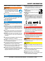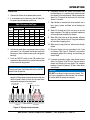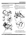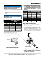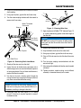
1
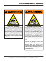
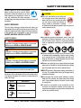
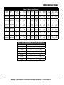
Operation and Parts Manual MODEL MGX Series concrete vibrator Revision #0 (03/26/12) To find the latest revision of this publication, visit our website at: www.multiquip.com THIS MANUAL MUST ACCOMPANY THE EQUIPMENT AT ALL TIMES. notes page 2 — MGX Series • operation and parts manual — rev. #0 (03/26/12) Silicosis/Respiratory Warnings WARNING WARNING SILICOSIS WARNING RESPIRATORY HAZARDS Grinding/cutting/drilling of masonry, concrete, metal and other materials with silica in their composition may give off dust or mists containing crystalline silica. Silica is a basic component of sand, quartz, brick clay, granite and numerous other minerals and rocks. Repeated and/or substantial inhalation of airborne crystalline silica can cause serious or fatal respiratory diseases, including silicosis. In addition, California and some other authorities have listed respirable crystalline silica as a substance known to cause cancer. When cutting such materials, always follow the respiratory precautions mentioned above. Grinding/cutting/drilling of masonry, concrete, metal and other materials can generate dust, mists and fumes containing chemicals known to cause serious or fatal injury or illness, such as respiratory disease, cancer, birth defects or other reproductive harm. If you are unfamiliar with the risks associated with the particular process and/or material being cut or the composition of the tool being used, review the material safety data sheet and/or consult your employer, the material manufacturer/supplier, governmental agencies such as OSHA and NIOSH and other sources on hazardous materials. California and some other authorities, for instance, have published lists of substances known to cause cancer, reproductive toxicity, or other harmful effects. Control dust, mist and fumes at the source where possible. In this regard use good work practices and follow the recommendations of the manufacturers or suppliers, OSHA/NIOSH, and occupational and trade associations. Water should be used for dust suppression when wet cutting is feasible. When the hazards from inhalation of dust, mists and fumes cannot be eliminated, the operator and any bystanders should always wear a respirator approved by NIOSH/MSHA for the materials being used. mgx Series • operation and parts manual — rev. #0 (03/26/12) — page 3 Table of Contents MGX Series Concrete Vibrator Silicosis/Respiratory Warnings................................. 3 Table Of Contents..................................................... 4 Parts Ordering Procedures....................................... 5 Safety Information................................................. 6-9 Specifications......................................................... 10 Dimensions............................................................. 11 General Information........................................... 12-13 Components........................................................... 14 Operation................................................................ 15 Maintenance...................................................... 16-18 Troubleshooting...................................................... 19 Explanation Of Code In Remarks Column............. 20 Suggested Spare Parts.......................................... 21 Component Drawings Motor Assy......................................................... 22-23 Shaft/Head Assy................................................ 24-27 Terms And Conditions Of Sale — Parts................. 28 NOTICE Specifications and part numbers are subject to change without notice. page 4 — MGX Series • operation and parts manual — rev. #0 (03/26/12) www.multiquip.com Parts Ordering Procedures Ordering parts has never been easier! choose from three easy options: order via internet (dealers only): Best deal! Effective: January 1st, 2006 If you have an MQ Account, to obtain a Username and Password, E-mail us at: parts@multiquip. com. Order parts on-line using Multiquip’s SmartEquip website! ■ View Parts Diagrams ■ Order Parts ■ Print Specification Information To obtain an MQ Account, contact your District Sales Manager for more information. Use the internet and qualify for a 5% discount on Standard orders for all orders which include complete part numbers.* Goto www.multiquip.com and click on Order Parts to log in and save! Note: Discounts Are Subject To Change order via Fax (dealers only): All customers are welcome to order parts via Fax. domestic (uS) Customers dial: 1-800-6-PARTS-7 (800-672-7877) Fax your order in and qualify for a 2% discount on Standard orders for all orders which include complete part numbers.* Note: Discounts Are Subject To Change order via phone: domestic (uS) dealers Call: 1-800-427-1244 non-dealer Customers: Contact your local Multiquip Dealer for parts or call 800-427-1244 for help in locating a dealer near you. International Customers should contact their local Multiquip Representatives for Parts Ordering information. When ordering parts, please supply: ❒ ❒ ❒ ❒ ❒ ❒ dealer account number dealer name and address Shipping address (if different than billing address) return Fax number applicable Model number Quantity, part number and description of each part ❒ Specify preferred Method of Shipment: ✓ UPS/Fed Ex ✓ DHL ■ Priority One ✓ Truck ■ Ground ■ Next Day ■ Second/Third Day NOTICE All orders are treated as Standard Orders and will ship the same day if received prior to 3PM PST. We aCCepT all MaJor CrediT CardS! mgx Series • operation and parts manual — rev. #0 (03/26/12) — page 5 Safety Information do noT operate or service the equipment before reading the entire manual. Safety precautions should be followed at all times when operating this equipment. Failure to read and understand the safety messages and operating instructions could result in injury to yourself and others. SaFeTy MeSSageS The four safety messages shown below will inform you about potential hazards that could injure you or others. The safety messages specifically address the level of exposure to the operator and are preceded by one of four words: danger, Warning, CauTion or noTiCe. SaFeTy SyMBolS danger Indicates a hazardous situation which, if not avoided, Will result in deaTH or SeriouS inJury. perSonal SaFeTy CauTion Stay alert, watch what you are doing and use common sense when operating a power tool. Do not use a power tool while you are tired or under the influence of drugs, alcohol or medication. A moment of inattention while operating power tools may result in serious personal injury. Use personal protective equipment. Always wear eye protection. Protective equipment such as dust mask, non-skid safety shoes, hard hat, or hearing protection used for appropriate conditions will reduce personal injuries.. Warning Indicates a hazardous situation which, if not avoided, Could result in deaTH or SeriouS inJury. CauTion Indicates a hazardous situation which, if not avoided, Could result in Minor or ModeraTe inJury. NOTICE Addresses practices not related to personal injury. Potential hazards associated with the operation of this equipment will be referenced with hazard symbols which may appear throughout this manual in conjunction with safety messages. Symbol Safety Hazard Burn hazards Prevent unintentional starting. Ensure the switch is in the off position before connecting to power source, picking up or carrying the tool. Carrying power tools with your finger on the switch or energizing power tools that have the switch on can cause accidents. Remove any adjusting key or wrench before turning the power tool on. A wrench or a key left attached to a rotating part of the power tool may result in personal injury. do noT overreach. Keep proper footing and balance at all times. This enables better control of the power tool in unexpected situations. Dress properly. Do not wear loose clothing or jewelry. Keep your hair, clothing and gloves away from moving parts. Loose clothes, jewelry or long hair can be caught in moving parts. If devices are provided for the connection of dust extraction and collection facilities, ensure these are connected and properly used. Use of dust collection can reduce dust-related hazards. Electric shock hazards page 6 — MGX Series • operation and parts manual — rev. #0 (03/26/12) Safety Information general poWer Tool SaFeTy WarningS Warning Read all safety warnings and all instructions. Failure to follow the warnings and instructions may result in electric shock, fire and/or serious injury. Save all warnings and instructions for future reference. NOTICE The term "power tool" in the warnings refers to your mains-operated (corded) power tool. WorK area SaFeTy never use accessories or attachments that are not recommended by Multiquip for this equipment. Damage to the equipment and/or injury to user may result. alWayS know the location of the nearest fire extinguisher. alWayS know the location of the nearest first aid kit. alWayS know the location of the nearest phone or keep a phone on the job site. Also, know the phone numbers of the nearest ambulance, doctor and fire department. This information will be invaluable in the case of an emergency. NOTICE Keep work area clean and well lit. Cluttered or dark areas invite accidents. do noT operate power tools in explosive atmospheres, such as in the presence of flammable liquids, gases or dust. Power tools create sparks which may ignite the dust or fumes. Keep children and bystanders away while operating a power tool. Distractions can cause you to lose control. alWayS clear the work area of any debris, tools, etc. that would constitute a hazard while the equipment is in operation. No one other than the operator is to be in the working area when the equipment is in operation. do noT use the equipment for any purpose other than its intended purpose or application. This equipment should only be operated by trained and qualified personnel, 18 years of age and older. Whenever necessary, replace nameplate, operation and safety decals when they become difficult read. Manufacturer does not assume responsibility for any accident due to equipment modifications. Unauthorized equipment modification will void all warranties. MoTor and FleXSHaFT SaFeTy danger alWayS wear rubber insulated gloves and boots when holding the flexshaft during operation. The possibility of electrocution exists causing equipment damage and severe bodily harm even death! danger If applicable, periodically check insulation resistance. The possibility of electrocution exists causing equipment damage and severe bodily harm even death! Warning never attempt to run the core outside the casing assembly for any reason. CauTion do noT carry plugged-in motor with finger on the switch. never carry the motor by the cord. Use the carrying handle. alWayS check the vibrator motor for loosened hardware such as nuts and bolts before starting. Keep the cord from heat, oil, and sharp objects. do noT overload the motor. It will do a better and safer job at the rate for which it was designed. mgx Series • operation and parts manual — rev. #0 (03/26/12) — page 7 Safety Information do noT expose vibrator motor to rain. do noT use vibrator motor in damp or wet locations without proper electrical circuits. do noT immerse the motor part in concrete. alWayS keep clear of rotating or moving parts while operating the vibrator motor. never leave the machine unattended while running. alWayS disconnect the motor from the power source when not in use, before servicing, and when changing flexible shafting and vibrator heads. Allow the vibrator motor to cool before servicing. Contact with hot components can cause serious burns. Before each use, alWayS check the motor to make certain that there are no damaged parts and that all parts function properly (such as switch, cord housing). If any damage or malfunctioning parts are found, have them repaired or replaced by an authorized service facility. NOTICE Secure forms. Make sure the form work is well made and braced to withstand the stresses made by vibration. Keep vibrator motor clean for better and safer operation. alWayS store equipment properly when it is not being used. Equipment should be stored in a clean, dry location out of the reach of children and unauthorized personnel. Use only factory-authorized replacement parts. Store idle vibrator motor. When not in use, motor should be stored in a dry, safe storage area. eleCTriCal SaFeTy CauTion Power tools must match the outlet. never modify the plug in any way. do noT use any adapter plugs with earthed (grounded) power tools. Unmodified plugs and matching outlets will reduce risk of electric shock. Avoid body contact with earthed or grounded surfaces such as pipes, radiators, ranges and refrigerators. There is an increased risk of electric shock if your body is earthed or grounded. do noT expose power tools to rain or wet conditions. Water entering a power tool will increase the risk of electric shock. do noT abuse power cord. never use the cord for carrying, pulling or unplugging the power tool. Keep cord away from heat, oil sharp edges or moving parts. Damaged or entangled cords increase the risk of electric shock. When operating a power tool outdoors, use an extension cord suitable for outdoor use. Use of a cord suitable for outdoor use reduces the risk of electric shock. This unit is double-insulated. The double-insulation between the electric-conducting part and the outside frame makes grounding unnecessary. However, if parts are replaced with wrong parts or assembled incorrectly, the vibrator may become unsafe to operate. Use only Multiquip recommended replacement parts. When applicable, use a protection wiring device, such as a Ground Fault Circuit Interrupter, for the protection of personnel. Operate electric motor only at the specified voltage indicated on the nameplate. do noT spray water onto electric motor. do noT yank the cord to disconnect it from the receptacle. Grasp the plug itself to disconnect it. alWayS make sure the ON/OFF switch on the electric motor is in the OFF position when not in use and before inserting the power plug into an AC receptacle. Before plugging the motor into a power source, alWayS remove any wrenches or other tools from the motor, shaft, and head that were used for assembly. page 8 — MGX Series • operation and parts manual — rev. #0 (03/26/12) Safety Information power Cord/Cable Safety danger alWayS use a grounded 3-wire extension cord that has a 3-prong grounding plug, and a 3-pole receptacle that accepts the plug on the concrete vibrator motor. do noT reMove THe grounding pin FroM THe plug! never let power cords or cables lay in water. never use damaged or worn cables or cords when connecting equipment to generator. Inspect for cuts in the insulation. never grab or touch a live power cord or cable with wet hands. The possibility exists of electrical shock, electrocution or death. Make sure power cables are securely connected. Incorrect connections may cause electrical shock and damage to the vibrator motor. CauTion Ensure that cables and cords will not be tripped over. NOTICE alWayS make certain that proper power or extension cord has been selected for the job. Use only extension cords that are intended for outdoor use and so marked. Use only the gauge wire and length of cord recommended for the motor size. If in doubt, go to the next heavier gauge. (The smaller the gauge number, the heavier the cord.) Disconnect the plug from the power source and/or the battery pack from the power tool before making any adjustments, changing accessories, or storing power tools. Such preventive safety measures reduce the risk of starting the power tool accidentally. Store idle power tools out of the reach of children and do not allow persons unfamiliar with the power tool or these instructions to operate the power tool. Power tools are dangerous in the hands of untrained users. Maintain power tools. Check for misalignment or binding of moving parts, breakage of parts and any other condition that may affect the power tool's operation. If damaged, have the power tool repaired before use. Many accidents are caused by poorly maintained power tools. Keep cutting tools sharp and clean. Properly maintained cutting tools with sharp cutting edges are less likely to bind and are easier to control. Use the power tool, accessories and tool bits etc. in accordance with these instructions, taking into account the working conditions and the work to be performed. Use of the power tool for operations different from those intended could result in a hazardous situation. ServiCe Have your power tool serviced by a qualified repair person using only identical replacement parts. This will ensure that the safety of the power tool is maintained. environMenTal SaFeTy/deCoMMiSSioning NOTICE poWer Tool uSe and Care do noT pour waste or oil directly onto the ground, down a drain or into any water source. do noT force the power tool. Use the correct power tool for your application. The correct power tool will do the job better and safer at the rate for which it was designed. Contact your country's Department of Public Works or recycling agency in your area and arrange for proper disposal of any electrical components, waste or oil associated with this equipment. do noT use the power tool if the switch does not turn it on and off. Any power tool that cannot be controlled with the switch is dangerous and must be repaired. When the life-cycle of this equipment is over it is recommended that the head casing and all other metal parts be sent to a recycling center. mgx Series • operation and parts manual — rev. #0 (03/26/12) — page 9 Specifications Table 1. Vibrator Specifications 120 Volt Models 240 Volt Models Amps 120V (240V) Watts Head in. (mm) Shaft Dia in. (mm) Amplitude in. (mm) Frequency Hz (vpm) Shaft Length ft. (m) Overall Length ft. (m) Motor Weight lb. (kg) Shaft/ Head Weight lb. (kg) Total Weight lb. (kg) MGX12325 MGX22325 3.8 (2.1) 280 .905 (23) .79 (20) .047 (1.2) 12,000 to 15,500 (200 to 258) 8.2 (2.5) 9.5 (2.9) 6.4 (2.9) 5.07 (2.3) 11.5 (5.2) MGX12810 MGX22810 3.8 (2.1) 280 1.10 (28) .98 (25) .070 (1.8) 12,000 to 15,500 (200 to 258) 3.2 (1.0) 4.7 (1.4) 6.4 (2.9) 3.08 (1.4) 9.5 (4.3) MGX12825 MGX22825 3.8 (2.1) 280 1.10 (28) .98 (25) .070 (1.8) 12,000 to 15,500 (200 to 258) 8.2 (2.5) 9.5 (2.9) 6.4 (2.9) 5.07 (2.3) 11.5 (5.2) MGX13225 MGX23225 3.8 (2.1) 280 1.25 (32) .98 (25) .075 (1.9) 12,000 to 15,500 (200 to 258) 8.2 (2.5) 9.5 (2.9) 6.4 (2.9) 3.08 (1.4) 9.5 (4.3) MGX13810 MGX23810 3.8 (2.1) 280 1.5 (38) .98 (25) .079 (2.0) 12,000 to 15,500 (200 to 258) 3.2 (1.0) 4.7 (1.4) 6.4 (2.9) 5.07 (2.3) 11.5 (5.2) MGX13825 MGX23825 3.8 (2.1) 280 1.5 (38) .98 (25) .079 (2.0 12,000 to 15,500 (200 to 258) 8.2 (2.5) 9.5 (2.9) 6.4 (2.9) 3.08 (1.4) 9.5 (4.3) Table 2. Replacement Heads and Shafts Specifications Head/Shaft Model Head Diameter in. (mm) Shaft Length ft (m) MGX2325 .9 (23) 8.2 (2.5) MGX2810 1.10 (28) 3.2 (1.0) MGX2825 1.10 (28) 8.2 (2.5) MGX3225 1.25 (32) 8.2 (2.5) MGX3810 1.5 (38) 3.2 (1.0) MGX3825 1.5 (38) 8.2 (2.5) page 10 — MGX Series • operation and parts manual — rev. #0 (03/26/12) dimensions Table 3. Dimensions Overall Shaft Head (A) Length (B) Length (C) in. (mm) ft. (m) ft. (m) 120 Volt Models 240 Volt Models MGX12325 MGX22325 .905 (23) 8.2 (2.5) 9.5 (2.9) MGX12810 MGX22810 1.10 (28) 3.2 (1.0) 4.7 (1.4) MGX12825 MGX22825 1.10 (28) 8.2 (2.5) 9.5 (2.9) MGX13225 MGX23225 1.25 (32) 8.2 (2.5) 9.5 (2.9) MGX13810 MGX23810 1.5 (38) 3.2 (1.0) 4.7 (1.4) MGX13825 MGX23825 1.5 (38) 8.2 (2.5) 9.5 (2.9) C B A Figure 1. MGX Vibrator Dimensions mgx Series • operation and parts manual — rev. #0 (03/26/12) — page 11 general information The MGX Vibrator has a double-insulated motor (no ground necessary) with advanced and user-friendly design. The motor is lightweight and durable with an aluminum motor case. The frontend closed-motor design prevents any invasion of mortar and foreign material from the front. Vibration-dampening handle grip reduces operator fatigue. Original cord protector gives flexibility to input cord for longer cord life. vibration range Vibration range (Figure 2) can be defined as "Area of Influence". This area of influence (vibrating radius) is the distance from the center of the vibrator to the outer most edge. AREA OF INFLUENCE (VIBRATING RADIUS) R Multiquip's shaft/heads are designed to work in medium to high slump concrete. Typical applications include small pours, slabs driveways, stem walls and footings. A vibrating steel head is attached to one end of the flexshaft. This head generates vibration via an eccentric rotator that consolidates the concrete by removing air pockets. The round head design allows for the transmission of vibration in all directions. D VIBRATOR HEAD INSERTION SPACING Why vibrate concrete To ensure optimum strength and durability, vibration of fresh concrete is an important requirement. Vibration or compaction is the principal method for consolidation of concrete. Figure 2. Vibrator Radius/Spacing Table 4 shows the vibration radius and spacing for a given vibrator head diameter. Table 4. Vibrating Radius/Insertion Spacing Consolidation Consolidation eliminates pockets of aggregate and air bubbles maximizing strength, eliminating surface voids. Vibrators consolidate concrete by transmitting shock waves which allow the aggregate to float freely while pushing lighter trapped air up and out of the concrete mix. A properly consolidated concrete pour will display a thin line of mortar appearing along the form near the vibrator and the coarse aggregate has been dispersed evenly throughout the pour and is not visible. vibration time Vibration time depends on frequency. The higher the frequency, the less vibration time is required for the job. HeadDia. in. (mm)# Vibration Radius (R) in. (mm) Vibrator Spacing (D) in. (mm) MGX12325 MGX22325 .9 (23) 4 (102) 6 (152) MGX12810 MGX22810 1.1 (28) 5.5 (140) 8.25 (210) MGX12825 MGX22825 1.1 (28) 5.5 (140) 8.25 (210) MGX13225 MGX23225 1.25 (32) 8 (203) 12 (305) MGX13810 MGX23810 1.5 (38) 12 (305) 18 (427) MGX13825 MGX23825 1.5 (38) 12 (305) 18 (427) 120 Volt Models 240 Volt Models NOTICE Radius (area of influence R) and vibrator head spacing (D) are expressed in inches/millimeters. Radius and distance values expressed in Table 4 are only to be used as a general guide. Values are subject to change. page 12 — MGX Series • operation and parts manual — rev. #0 (03/26/12) general information NOTICE NOTICE Vibrator head spacing distance (D) is calculated by multiplying the vibrating head radius (R) (area of influence) by 1.5. When determining which head to choose it is important to access the application. Mainly what are the dimensions of the application. Select the vibrator head based on its radiating radius characteristics. Reference Table 4. Select the vibrating head that covers the largest possible area without excessive overkill. This will allow for more efficient productivity. General rule of thumb is DO NOT select a vibrator head which has a vibration radius of more than twice the width of the form. Vibration techniques, vibrator head placement and spacing as referenced in the "General Information" and "Operation" sections of this manual is only to be used as a guideline. Multiquip assumes no responsibility for vibrator operating techniques referenced in this manual. The consolidation of concrete has many mitigating factors that must be considered such as slump, mix, depth of vibrator, vibrator spacing, vibration time, vibration frequency, temperature. All of these factors must be considered when the consolidation (vibration) of concrete is required. Example: If the form width is 9 inches (229 mm) the selected vibrator head radius should not exceed an 18 inch (457 mm) radius. In this example the MGX3810 and MGX3825 head/shaft would be the recommended choice. Refer to Table 4 and Figure 3. AREA OF INFLUENCE (VIBRATING RADIUS) CONCRETE NO VIBRATION VIBRATOR HEAD INSERTION POINT FORM WIDTH CORRECT TOO SMALL AREA OF INFLUENCE (VIBRATING RADIUS) NO VIBRATION VIBRATOR HEAD INSERTION SPACING Figure 3. Head Selection mgx Series • operation and parts manual — rev. #0 (03/26/12) — page 13 components 1. ON/OFF Switch — Turns power on when pressed and off when released. 1 8 2 7 2. Power Cord — Connects to the power source. (120V or 220V depending on model). Make sure to check voltage on motor nameplate and connect to the appropriate power source. 3. Motor — 120V or 240V depending on model. 4. Flexible Shaft — Transmits rotary motion from the motor to the head. 3 6 5. Vibrator Head — Generates vibration via an eccentric rotator that consolidates the concrete by removing air pockets. 6. Coupler — Attaches the shaft/head assembly to the motor. 7. Air Intake —Air comes in and suctioned by the fan to cool the motor, then discharged at the rear of the motor. 8. Power Lock Button — Locks the ON/OFF Switch to the ON position. Lock is released when the ON/OFF Switch is pressed again. 4 5 Figure 4. MGX Vibrator Components page 14 — MGX Series • operation and parts manual — rev. #0 (03/26/12) operation operation 1. Connect the vibrator to the proper power source. 2. If an extension cord is necessary, refer to Table 5 for the correct type of extension cord to use. Table 5. Extension Cord Types Load in Watts Maximum Allowable Cable Length Current in Amperes At 100 Volts At 200 Volts #10 Wire #12 Wire #14 Wire #16 Wire 2.5 300 600 1000 ft. 600 ft. 375 ft. 250 ft. 5 600 1200 500 ft. 300 ft. 200 ft. 125 ft. 7.5 900 1800 350 ft. 200 ft. 125 ft. 100 ft. 10 1200 2400 250 ft. 150 ft. 100 ft. 15 1800 3600 150 ft. 100 ft. 65 ft. 20 2400 4800 125 ft. 75 ft. 50 ft. 6. Completely immerse the vibrator head quickly into the concrete mix at a verticle rate of about one foot per second (0.3 meters/second). Vibrate concrete for about 5 to 15 seconds for wet mixes. For stiff mixes vibrate 2-3 minutes. 7. Stop vibration of concrete mix when concrete has a level, glossy surface and there are no breaking air bubbles. 8. Slowly lift the head out of the mix using an up and down movement. This slight up and down movement will close the hole formed by the vibrator. 9. When lifting the head out of the concrete, withdraw slowly at a rate of about 3 sec./ft. Using this technique will avoid the re-trapping of air. 10. When near the top of the mix, withdraw the vibrator quickly. 3. Hold vibrator head above concrete pour when starting drive motor. This will prevent the vibrator head from bouncing on hard surfaces which could damage the bearings. 11. Re-insert vibrator into mix according to the "area of influence" See Figure 5. Establish a symmertical overlapping pattern for inserting and removing the vibrator head. 4. Push the ON/OFF switch to the ON position then immerse into the surface. Do not run the motor outside of the surface for long periods. 12. If concrete is poured in layers, allow vibrator to pass within 3 to 6 inches (76 to 152 mm.) into next layer to ensure the knitting of the two layers. The complete bonding of layers will prevent "lift lines" when forms are removed. NOTICE Pressing the Power Lock Button will lock the On/OFF switch to the ON position. 5. Keep flexshaft (Figure 5) straight as possible when operating. Sharp bends increase the load on the core and drive motor, which will result in early core failure and possible damage to the drive motor. 1-1/2 TIMES AREA OF INFLUENCE CORRECT NOTICE DO NOT use vibrator to move concrete laterally. This will cause segregation of the concrete. Use a shovel or similar device to spread the concrete. FLEX-SHAFT VIBRATOR HEAD VIBRATOR HEAD INCORRECT Figure 5. Vibrator Head Insertion mgx Series • operation and parts manual — rev. #0 (03/26/12) — page 15 maintenance DRIVE MOTOR inspection 1. Visually inspect the motor daily before use for defective or missing parts, and have repairs made before use. carbon brush replacement 1. To gain access to the carbon brushes, remove the body cover from the motor (see Figure 6). Body Cover 2. Remove the screw and washer securing the brush holder. 3. Inspect the brush and replace when they become worn to a length of 3/8". vibrator head lubrication (300 Hours) 1. Using a wrench, remove vibrator head tip (Figure 7) from vibrator head body. Have a cloth handy to catch any spilled oil. Screw (4) Vise Screw (2) Vibrator Head Rag Brush Holder (2) Washer (Poly Carbonate) - (2) Carbon Brush (2) Lubricate Cover Oil Screw (2) Figure 7. Adding Oil (Vibrator Head) 2. Drain old oil from vibrator head body (casing). Place oil in a suitable container. DO NOT pour oil on the ground. Figure 6. Carbon Brush Replacement page 16 — MGX Series • operation and parts manual — rev. #0 (03/26/12) maintenance NOTICE Dispose used vibrator head oil in accordance with city, local and state environmental guidlelines. 3. Fill vibrator head body with SAE 15 or AW MV ISO 46 type oil or equivalent. 4. DO NOT fill head body beyond capacity. Reference Table 6. NOTICE DO NOT overfill. Too much oil in the vibrator head will overload the drive motor. Table 6. Vibrator Head Oil Capacity 120 Volt Models 240 Volt Models Oil Capacity. oz. (ml)# MGX12325 MGX22325 2.4 (70) MGX12810 MGX22810 0.5 (15) MGX12825 MGX22825 2.4 (70) MGX13225 MGX23225 2.4 (70) MGX13810 MGX23810 0.5 (15) MGX13825 MGX23825 2.4 (70) vibrator head wear (300 Hours) 2. Replace vibrator shaft/head assembly if head diameter is at maximum wear as specified in Table 7. See Table 2 for available models and specifications. Shaft/head assemblies should be replaced by a qualified technician. Table 7. Vibrator Head Wear Diameter 120 Volt Models 240 Volt Models New Head Dia. in. (mm)# Head Dia. w/ Max Wear in. (mm) MGX12325 MGX22325 .905 (23) .842 (21.39) MGX12810 MGX22810 1.1 (28) 1.02 (25.91) MGX12825 MGX22825 1.1 (28) 1.02 (25.91) MGX13225 MGX23225 1.25 (32) 1.16 (29.46) MGX13810 MGX23810 1.5 (38) 1.39 (35.31) MGX13825 MGX23825 1.5 (38) 1.39 (35.31) shaft lubrication (200 Hours) 1. Place the vibrator on a suitable workbench. Make sure the area is clear of clutter. 2. Turn the plasticcoupler holding the shaft to the motor clockwise until completely loose (Figure 9). If the coupler does not come off easily, place motor in a vise and hit the coupler with a rubber mallet to loosen. Motor 1. Periodically measure the outside diameter (Figure 8) of the vibrator head casing. VIBRATOR HEAD CASING DIAMETER Plastic Coupler Figure 8. Vibrator Head Diameter Figure 9. Loosening Shaft Coupler 3. Gently pull out flexible shaft collar to access the flex shaft core crimp. See Figure 10. mgx Series • operation and parts manual — rev. #0 (03/26/12) — page 17 maintenance TPG T ICAN LUBR 4. Place a 5/16-inch wrench on the flat side of the motor shaft coupling. 5. Using a pair of pliers, grip the flex shaft core crimp. 6. Turn the motor coupling clockwise with the wrench to remove shaft from motor. Wrench WIRE BRUSH CLOTH Motor Threaded Connector WIRE CORE Figure 11. Cleaning Wire Core 11. Apply a light amout of DuBois "TPG" lubricant (Figure 11) or a good grade bearing grease to the entire length of the wire core. Flex Shaft Core Crimp Pliers Plastic Coupler NOTICE DO NOT force casing full of grease. A tightly packed casing will load the drive motor which could lead to overheating. 12. Reinstall wire core back into casing. 13. Align the flexible shaft core to the motor shaft. 14. Using a pair of pliers, grip the flex shaft core crimp. Flex Shaft Core Figure 10. Removing Shaft from Motor 7. Slowly pull the wire core from the shaft. 8. Inspect the core for broken wires, permanent set or other damage such as an area that indicates high wear or having overheated. If any of these conditions exist, replace shaft/head assembly. 15. Place a 5/16-inch wrench on the flat side of the motor shaft. 16. Turn the motor coupling counterclockwise with the wrench until tight. 17. Align and push the flexible shaft into the motor threaded connector. 18. Tighten the plastic coupler making sure shaft/head assembly is connected securely to the motor. 9. Use the core to push a cleaning patch through the casing to remove any old grease or foreign matter that may have accumulated inside the casing. NOTICE DO NOT use solvents to clean casing. Applying solvents to the core or casing may cause grease (lubricant) to breakdown, resulting in damage to the shaft. 10. Thoroughly clean wire core (Figure 11) if it is being reused. A wire brush may be required to remove hardened residue. page 18 — MGX Series • operation and parts manual — rev. #0 (03/26/12) troubleshooting Symptom Shaft Binding Leaking Vibrator Head Table 8. Vibrator Troubleshooting Possible Problem Solution Shaft kinked? Straighten out shaft. Defective shaft? Replace shaft/head. Too much oil in head casing? Fill head casing to recommended level. Head bearings/seals defective? Replace shaft/head. mgx Series • operation and parts manual — rev. #0 (03/26/12) — page 19 Explanation of Code in Remarks Column The following section explains the different symbols and remarks used in the Parts section of this manual. Use the help numbers found on the back page of the manual if there are any questions. NOTICE The contents and part numbers listed in the parts section are subject to change without notice. Multiquip does not guarantee the availability of the parts listed. SaMple parTS liST no. 1 2% 2% 3 4 parT no. parT naMe QTy. reMarKS 12345 BOLT .....................1 .....INCLUDES ITEMS W/% WASHER, 1/4 IN. ..........NOT SOLD SEPARATELY 12347 WASHER, 3/8 IN. ..1 .....MQ-45T ONLY 12348 HOSE ..................A/R ...MAKE LOCALLY 12349 BEARING ..............1 .....S/N 2345B AND ABOVE no. Column QTy. Column numbers used — Item quantity can be indicated by a number, a blank entry, or A/R. A/R (As Required) is generally used for hoses or other parts that are sold in bulk and cut to length. A blank entry generally indicates that the item is not sold separately. Other entries will be clarified in the “Remarks” Column. reMarKS Column Some of the most common notes found in the “Remarks” Column are listed below. Other additional notes needed to describe the item can also be shown. assembly/Kit — All items on the parts list with the same unique symbol will be included when this item is purchased. unique Symbols — All items with same unique symbol Indicated by: “INCLUDES ITEMS W/(unique symbol)” (@, #, +, %, or >) in the number column belong to the same assembly or kit, which is indicated by a note in the “Remarks” column. Serial number Break — Used to list an effective serial number range where a particular part is used. duplicate item numbers — Duplicate numbers indicate multiple part numbers, which are in effect for the same general item, such as different size saw blade guards in use or a part that has been updated on newer versions of the same machine. NOTICE When ordering a part that has more than one item number listed, check the remarks column for help in determining the proper part to order. parT no. Column numbers used — Part numbers can be indicated by a number, a blank entry, or TBD. TBD (To Be Determined) is generally used to show a part that has not been assigned a formal part number at the time of publication. A blank entry generally indicates that the item is not sold separately or is not sold by Multiquip. Other entries will be clarified in the “Remarks” Column. Indicated by: “S/N XXXXX AND BELOW” “S/N XXXX AND ABOVE” “S/N XXXX TO S/N XXX” Specific Model number use — Indicates that the part is used only with the specific model number or model number variant listed. It can also be used to show a part is NOT used on a specific model or model number variant. Indicated by: “XXXXX ONLY” “NOT USED ON XXXX” “Make/obtain locally” — Indicates that the part can be purchased at any hardware shop or made out of available items. Examples include battery cables, shims, and certain washers and nuts. “not Sold Separately” — Indicates that an item cannot be purchased as a separate item and is either part of an assembly/kit that can be purchased, or is not available for sale through Multiquip. page 20 — MGX Series • operation and parts manual — rev. #0 (03/26/12) Suggested Spare Parts mgx sERIES vIBRATORS 1 to 3 units Qty.P/NDescription 3 247458690 CARBON BRUSH 6X8 NOTICE Part numbers on this Suggested Spare Parts list may supersede/replace the part numbers shown in the following parts lists. mgx Series • operation and parts manual — rev. #0 (03/26/12) — page 21 Motor assy. page 22 — MGX Series • operation and parts manual — rev. #0 (03/26/12) Motor assy. NO. 1 2 3 4 4 8 9 10 11 11 15 16 17 18 19 20 21 23 24 25 26 28 29 30 32 33 35 36 38 39 40 41 42 43 44 45 46# 47 48 50 60 PART NO. 002240530 247458630 042506000 247010102 247010104 047110040 247458570 091505060 247010202 247010204 247216910 2474-58640 01160402 033910180 247458700 247458690 247346140 920211100 233010020 247458710 920110460 247910080 247460060 247446150 261011090 243011130 247346160 092404022 094010027 247458600 092404008 247458620 247458680 247458660 247458590 092404018 247461180 247460080 247460090 920110550 920900030 PART NAME QTY. REMARKS BOLT 5X30 SW/SUS 4 L-BRACKET 1 BEARING 6000ZZSG 1 ARMATURE ASSY./110-120V ...........................1................MGX1 ARMATURE ASSY./220-240V ...........................1................MGX2 BEARING 609ZZ 1 FAN GUIDE 1 SCREW 5X60 W/SW 2 STATOR ASSY. (110-120V)................................1................MGX1 STATOR ASSY. (220-240V) ...............................1................MGX2 STATOR INSULATION 1 CONDENSER ASSY. 1 SCREW 4X25 2 POLY CARBONATE WASHER M4 2 BRUSH HOLDER-L 1 CARBON BRUSH 6X8 2 FRAME 1 NAMEPLATE .....................................................1................CONTACT MQ PARTS DEPT. RIVET 2.3X5 4 BRUSH HOLDER-R 1 DECAL, CAUTION/COMBINATION....................1................NP-1046 WIRE INSULATION (L,R SET) ..........................1................INCLUDES ITEM W/# SWITCH COVER 1 CABTYRE CORD ASSY. W/PLUG 1 TERMINAL 2-SD 1 TERMINAL TGV1.25-4 1 TRIGGER SWITCH 1 SCREW 4X22 SUS 3 TAPPING SCREW 4X10 2 VIBRATION PROOF COVER 1 SCREW 4X8 SUS 2 BODY COVER 1 RUBBER PIN 1 CAP 1 SWITCH LOCK COVER 1 SCREW 4X18 SUS 1 CONTRACTION TUBE 25-40L 1 DUST PROOF SEET1 2 DUST PROOF SEET2 1 DECAL, DOUBLE INSULATION 1 DECAL, SET, MIKASA (L,R) 1 mgx Series • operation and parts manual — rev. #0 (03/26/12) — page 23 Shaft/Head assy. B38 B32 B28 B23 5 6 A 1 2 4 3 page 24 — MGX Series • operation and parts manual — rev. #0 (03/26/12) Shaft/Head assy. NO. PART NO. PART NAME QTY. REMARKS A 242913040 VIBRATING HEAD ASSY., .905 IN. (23 MM)......1 ...............MGX12325/MGX22325 INCLUDES ITEMS W/ # A 242913010 VIBRATING HEAD ASSY., 1.1 IN. (28 MM)........1 ...............MGX12810/MGX22810 MGX12825/MGX22825 INCLUDES ITEMS W/ $ A 242913020 VIBRATING HEAD ASSY., 1.25 IN. (32 MM) 1 MGX13225/MGX23225 INCLUDES ITEMS W/ % A 242913030 VIBRATING HEAD ASSY., 1.50 IN. (38 MM)......1 ...............MGX13810/MGX23810 MGX13825/MGX23825 INCLUDES ITEMS W/ @ B23 242923330 LEAD SHAFT ASSY., 8.2 FT. (2.5 METERS).....1 ...............MGX12325/MGX22325 INCLUDES ITEM W/ + B28 242923220 LEAD SHAFT ASSY., 3.2 FT. (1 METER) . ........1 ...............MGX12810/MGX22810 INCLUDES ITEM W/ & B28 242923340 LEAD SHAFT ASSY., 8.2 FT. (2.5 METERS).....1 ...............MGX12825/MGX22825 INCLUDES ITEM W/ & B32 242923350 LEAD SHAFT ASSY., 8.2 FT. (2.5 METERS) ....1 ...............MGX13225/MGX23225 INCLUDES ITEM W/ ^ B38 242923300 LEAD SHAFT ASSY., 3.2 FT. (1 METER) . ........1 ...............MGX13810/MGX23810 INCLUDES ITEM W/ * B38 242923360 LEAD SHAFT ASSY., 8.2 FT. (2.5 METERS) ....1 ...............MGX13825/MGX23825 INCLUDES ITEM W/ * mgx Series • operation and parts manual — rev. #0 (03/26/12) — page 25 Shaft/Head assy. B38 B32 B28 B23 5 6 A 1 2 4 3 page 26 — MGX Series • operation and parts manual — rev. #0 (03/26/12) Shaft/Head assy. NO. PART NO. PART NAME QTY. REMARKS 1# 242953040 CASE ASSY........................................................1................MGX12325/MGX22325 1$ 242953010 CASE ASSY........................................................1................MGX12810/MGX22810 MGX12825/MGX22825 1% 242953020 CASE ASSY........................................................1................MGX13225/MGX23225 1@ 242953030 CASE ASSY........................................................1................MGX13810/MGX23810 MGX13825/MGX23825 2# 080300060 SNAP RING........................................................1................MGX12325/MGX22325 2$ 080300070 SNAP RING .......................................................1................MGX12810/MGX22810 MGX12825/MGX22825 2% 080300080 SNAP RING .......................................................1................MGX13225/MGX23225 2@ 080300090 SNAP RING........................................................1................MGX13810/MGX23810 MGX13825/MGX23825 3# 242336950 ECCENTRIC ROTATOR......................................1................MGX12325/MGX22325 3$ 242321540 ECCENTRIC ROTATOR......................................1................MGX12810/MGX22810 MGX12825/MGX22825 3% 242321550 ECCENTRIC ROTATOR......................................1................MGX13225/MGX23225 3@ 242321560 ECCENTRIC ROTATOR......................................1................MGX13810/MGX23810 MGX13825/MGX23825 4# 042500697 BEARING 697ZZSG/MC3 .................................4................MGX12325/MGX22325 4$ 040300608 BEARING 608/MC3 ...........................................4................MGX12810/MGX22810 MGX12825/MGX22825 4% 040300629 BEARING 629/MC3 ...........................................4................MGX13225/MGX23225 4@ 040006200 BEARING 6200 . ................................................4................MGX13810/MGX23810 MGX13825/MGX23825 5+ 064901030 OIL SEAL, DS7144 . ..........................................1................MGX12325/MGX22325 5& 060600010 OIL SEAL, VC-8184 . .........................................1................MGX12810/MGX22810 MGX12825/MGX22825 5^ 060600020 OIL SEAL, VC-9225 . .........................................1................MGX13225/MGX23225 060201010 OIL SEAL, SC-10257 . .......................................1................MGX13810/MGX23810 5* MGX13825/MGX23825 6+&^* FLEXIBLE SHAFT ............................................1................NOT SOLD SEPARATELY mgx Series • operation and parts manual — rev. #0 (03/26/12) — page 27 Terms and Conditions of Sale — Parts payMenT TerMS 5. Parts must be in new and resalable condition, in the original Multiquip package (if any), and with Multiquip part numbers clearly marked. 6. The following items are not returnable: Multiquip reserves the right to quote and sell direct to Government agencies, and to Original Equipment Manufacturer accounts who use our products as integral parts of their own products. a. SpeCial eXpediTing ServiCe Terms of payment for parts are net 30 days. FreigHT poliCy All parts orders will be shipped collect or prepaid with the charges added to the invoice. All shipments are F.O.B. point of origin. Multiquip’s responsibility ceases when a signed manifest has been obtained from the carrier, and any claim for shortage or damage must be settled between the consignee and the carrier. b. MiniMuM order The minimum charge for orders from Multiquip is $15.00 net. Customers will be asked for instructions regarding handling of orders not meeting this requirement. reTurned goodS poliCy Return shipments will be accepted and credit will be allowed, subject to the following provisions: 1. A Returned Material Authorization must be approved by Multiquip prior to shipment. 2. Obsolete parts. (If an item is in the price book and shows as being replaced by another item, it is obsolete.) Any parts with a limited shelf life (such as gaskets, seals, “O” rings, and other rubber parts) that were purchased more than six months prior to the return date. c. Any line item with an extended dealer net price of less than $5.00. d. Special order items. e. Electrical components. f. Paint, chemicals, and lubricants. g. Decals and paper products. h. Items purchased in kits. 7. The sender will be notified of any material received that is not acceptable. To obtain a Return Material Authorization, a list must be provided to Multiquip Parts Sales that defines item numbers, quantities, and descriptions of the items to be returned. 8. Such material will be held for five working days from notification, pending instructions. If a reply is not received within five days, the material will be returned to the sender at his expense. a. The parts numbers and descriptions must match the current parts price list. 9. b. The list must be typed or computer generated. Credit on returned parts will be issued at dealer net price at time of the original purchase, less a 15% restocking charge. c. The list must state the reason(s) for the return. d. The list must reference the sales order(s) or invoice (s) under which the items were originally purchased. e. The list must include the name and phone number of the person requesting the RMA. 3. A copy of the Return Material Authorization must accompany the return shipment. 4. Freight is at the sender’s expense. All parts must be returned freight prepaid to Multiquip’s designated receiving point. 10. In cases where an item is accepted, for which the original purchase document can not be determined, the price will be based on the list price that was effective twelve months prior to the RMA date. A $35.00 surcharge will be added to the invoice for special handling including bus shipments, insured parcel post or in cases where Multiquip must personally deliver the parts to the carrier. liMiTaTionS oF Seller’S liaBiliTy Multiquip shall not be liable hereunder for damages in excess of the purchase price of the item with respect to which damages are claimed, and in no event shall Multiquip be liable for loss of profit or good will or for any other special, consequential or incidental damages. liMiTaTion oF WarranTieS No warranties, express or implied, are made in connection with the sale of parts or trade accessories nor as to any engine not manufactured by Multiquip. Such warranties made in connection with the sale of new, complete units are made exclusively by a statement of warranty packaged with such units, and Multiquip neither assumes nor authorizes any person to assume for it any other obligation or liability whatever in connection with the sale of its products. Apart from such written statement of warranty, there are no warranties, express, implied or statutory, which extend beyond the description of the products on the face hereof. Effective: February 22, 2006 11. Credit issued will be applied to future purchases only. priCing and reBaTeS Prices are subject to change without prior notice. Price changes are effective on a specific date and all orders received on or after that date will be billed at the revised price. Rebates for price declines and added charges for price increases will not be made for stock on hand at the time of any price change. page 28 — MGX Series • operation and parts manual — rev. #0 (03/26/12) notes mgx Series • operation and parts manual — rev. #0 (03/26/12) — page 29 Operation and Parts Manual HERE’S HOW TO GET HELP PLEASE HAVE THE MODEL AND SERIAL NUMBER ON-HAND WHEN CALLING United StateS Multiquip Corporate Office 18910 Wilmington Ave. Carson, CA 90746 Contact: [email protected] MQ Parts Department Tel. (800) 421-1244 Fax (800) 537-3927 Service Department 800-421-1244 310-537-3700 800-427-1244 310-537-3700 Fax: 800-672-7877 Fax: 310-637-3284 Warranty Department Fax: 310-537-4259 800-421-1244 310-537-3700 Fax: 310-943-2249 Technical Assistance 800-478-1244 Fax: 310-943-2238 mexico United Kingdom MQ Cipsa Multiquip (UK) Limited Head Office Carr. Fed. Mexico-Puebla KM 126.5 Momoxpan, Cholula, Puebla 72760 Mexico Contact: [email protected] Tel: (52) 222-225-9900 Fax: (52) 222-285-0420 Unit 2, Northpoint Industrial Estate, Globe Lane, Dukinfield, Cheshire SK16 4UJ Contact: [email protected] Tel: 0161 339 2223 Fax: 0161 339 3226 Canada Multiquip 4110 Industriel Boul. Laval, Quebec, Canada H7L 6V3 Contact: [email protected] Tel: (450) 625-2244 Tel: (877) 963-4411 Fax: (450) 625-8664 © COPYRIGHT 2012, MULTIQUIP INC. Multiquip Inc, the MQ logo are registered trademarks of Multiquip Inc. and may not be used, reproduced, or altered without written permission. All other trademarks are the property of their respective owners and used with permission. This manual MUsT accompany the equipment at all times. This manual is considered a permanent part of the equipment and should remain with the unit if resold. The information and specifications included in this publication were in effect at the time of approval for printing. Illustrations, descriptions, references and technical data contained in this manual are for guidance only and may not be considered as binding. Multiquip Inc. reserves the right to discontinue or change specifications, design or the information published in this publication at any time without notice and without incurring any obligations. Your Local Dealer is: