1
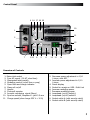
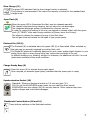
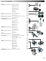
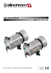
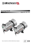
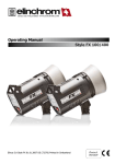
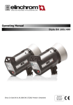
elinca sa switzerland www.elinchrom.com Operating Manual Digital 1200 RX Digital 2400 RX Version 230 V - 10256 Version 110V - 10255 Elinca S.A Digital RX 01.06.2007 ENG (73256) Printed in Switzerland 230 V - 10258 110 V - 10257 English Table of contents Introduction 2 Declaration of conformity, disposal and recycling, CE marking 3 Before you start, Safety notice 4 Control Panel 5 Operating instructions 6 Functions 6, 7 Relation of power between the outlets 8 Fuse 8 Flasheads 9 Symmertical/Asymmetrical power distribution 10 Flashheads compatibility 10 Flashhead types 11 Wireless remote control and flash triggering 12 Troubleshooting 12 Elinchrom Accessories 13 Guarantee 14 P.S: Technical data subject to change. The listed values are guide values which may vary due to tolerances in components used. 1 Introduction The Elinchrom Digital RX is manufactured by Elinca S.A. CH -1020 Renens/Switzerland Dear Photographer, Thank you for buying your Digital RX flash generator. All Elinchrom products are manufactured using the most advanced technology. Carefully selected components are used to ensure the highest quality and the equipment is submitted to many controls both during and after manufacture. We trust that it will give you many years of reliable service. All Digital RX flash units are manufactured for the studio and location use of professional photographers. Only by observance of the information given, can you secure your warranty, prevent possible damage and increase the life of this equipment. Digital RX Flash Generator The quality of light and exceptional performance is the result of long research, application of demanding principles, the long experience of ELINCHROM in lighting products for the studio and the utilization of the latest technology in this area. Totally integrated to the range of the ELINCHROM flashes, the Digital RX Flash generator maintain the traditional look and function that is ELINCHROM. FCC Class B Compliance Statement Note: This equipement has been tested and found to comply with the limits for a class B digital device, pursuant to Part 15 of the FCC Rules and meets all requirements of the Canadian Interference-Causing Equipement Regulations. These limits are designed to provide reasonable protection against harmful interference in a residential installation. This equipement generates, uses, and can radiate radio frequency energy and, if not installed and used in accordance with the instruction manual, may cause harmful interference to radio communications. However, there is no guarantee that interference will not occur in a particular installation. If this equipement does not cause harmful interferences to radio or television reception, which can be determined by turning the equipement off and on, the user is encouraged to correct the interferences by one or more of the following measures: - Reorient or relocate the receiving antenna. - Increase the separation between the equipement and receiver. - Connect the equipement into an outlet on a circuit different from that to which the receiver is connected. - Consult the dealer or an experienced radio/TV technician for help. ELINCA S.A. is not responsible for any radio or television interference caused by unauthorised modifications of this equipement or the substitution or attachment of connecting cables and equipement other than those specified by ELINCA S.A. The correction of interference caused by such unauthorised modification, substitution or attachment will be the responsibility of the user. 2 Declaration of conformity This device complies with Part 15 of the FCC Rules. Operation is subject to the following two conditions: 1. This device may not cause harmful interference. 2. This device must accept any interference received, including interference that may cause undesired operation. Product name: Professional Studio Flash Generator Trade name: ELINCHROM Model number(s): Digital RX Name of responsible party: Elinca S.A Av. De Longemalle 11 1020 Renens / Switzerland Phone : +41 21 637 26 77 We, ELINCA S.A., hereby declare that the equipement bearing the trade name and model number specified above was tested conforming to the applicable FCC rules, and that all the necessary steps have been taken and are in force to assure that the production units of the same equipement will continue to comply with the Comissions requirements. Disposal and recycling This device has been manufactured to the highest possible degree from materials which can be recycled or disposed of in a manner that is not enviromentally damaging. The device may be taken back after use to be recycled, provided that is returnedinaconditionthatistheresultofnormaluse.Anycomponentsnotreclaimed will be disposed of in a environmentally acceptable manner. If you have any question on disposal, please contact your local office or your local ELINCHROM agent (check our website for a list of all ELINCHROM agents world wide). CE marking The shipped version of this device complies with the requirements of ECC directives 89/336/ECC «Electromagnetic compatibility» and 73/23/ECC «Low voltage directive». Notational Conventions The meaning of the symbols and fonts used in this manual are as follows: ! i Pay particular attention to text marked with this symbol. Failure to observe this warning endangers your life, destroys the device, or may damage other equipement Supplementary information, remarks, and tips follow this symbol. Text which follows this symbol describes activities that must be performed in the order shown. «Quotation marks» indicate names of chapters or terms 3 Before you start ! User Safety Information • Keep flash units out of reach whenever possible. • Switch off when not in use and disconnect flashheads. • Do not use in restricted areas (like hospitals, etc.) • Do not use near flammable/explosive material. • It must be protected from dripping water and from extremely dusty conditions • The unit must ALWAYS be plugged into an EARTHED electrical socket. • This equipment should be used only in a dry environment • If the unit has been exposed to very cold conditions, sudden exposure to warm or humid air may cause condensation => the unit should acclimate for some time to prevent condensation. • There is high voltage and can be high currents, so please apply all the usual safety precautions when handling the unit, changing fuses, modelling lamps etc. • Do not open the unit. In the event of damage or apparent failure, contact a repair service or any Elinchrom agent or email: [email protected] • Always switch off the unit before connecting or disconnecting flashheads • Check always if flashhead connections are plugged in and locked correctly Flash Tubes and Modelling lamps • Flash tubes and modelling lamps in use are very hot! • Never touch a flash tube or lamp before the unit cooled down and is disconnected from the mains. • Do not fire flashes from short distance (less than 1m) directed to a person and avoid looking into the flashlight! • Keep generally distance to operating units. ! • • • • • • • Always switch off the unit before connecting or disconnecting flashheads! The head connector must always be locked correctly before any use. Never store liquids or drinks on the power pack panel or closed to the unit! Flash systems store electrical energy in capacitors by applying high voltage. For your safety, never open or disassemble your flashes. Only an authorised service engineer should open or attempt to repair the units. Internal defect charge capacitors may explode whilst the unit is in use, neve switch on a not proper working flash unit. 4 Control Panel 4 16 17 18 19 20 1 21 2 15 3 10 7 9 11 6 5 8 12 13 14 Overview of Controls 1. 2. 3. 4. 5. 6. 7. 8. 9. 10. 11. Mains inlet socket Fuse AC supply (16 AT, slow blow) Illuminated mains switch Modelling control (on/off free or prop) Open flash and charge indicator Slave cell on/off Handle Photocell receptor Acoustic recharging signal (Beep) Synchro-sockets, Amphenol + jack 3.5 mm Charge speed (slow charge 230 V = 10 A) 12. Decrease power adjustment in 1/10 f-stops, with ADF 13. Increase power adjustment in 1/10 f-stops 14. Power display 15. Socket for remote or USB - Multi Link 16. Increase modelling power 17. Decrease modelling power 18. Lamphead (on/off) outlet A 19. Lamphead (on/off) outlet B 20. Socket outlet A (with security catch) 21. Socket outlet B (with security catch) 5 Operating Instructions Before connecting the digital RX for the first time, make sure that your mains supply and the rating set on the equipment (electrical specification plate) are compatible to 110V or 230V. • • • • • • • • Connect lampheads ensuring that lamphead touches (18-19) are Off. Connect the mains cord in the inlet socket (1) Select charging rate (11) (" " slow position), only when the mains supply is too limited. Select modelling lamp setting (4) Connect the synchro lead (10) Check that the photocell’s switch (6) is in the required position. Use the touch buttons (12 - 13) to select the desired power. The open flash (5) will light up, indicating that the unit is ready for operation. Fonctions On/Off Switch (3) By pressing this touch button the Digital RX is switched on or off. This unit is protected by a thermal circuit breaker to avoid overheating. Should this occur, the unit turns off automatically and cannot be operated! After a break for cooling, the flash is ready again for operation. Digital Power Display (14) The actual flash power is displayed in a f-stop compatible format. The power range is 6 f-stops. The digital display, provides continuous power indication of the flash and modelling lamp. The controls cover a continuous output range from full power 1/1 to 1/32th in 1/10th f-stop steps. During charging or discharging the display "flashes". In case of overheating or malfunction, the display shows "ER" for error. Digital Power Regulation (12 and 13) The power control provides simultaneous and continuously variable adjustment of the modelling lamp and the flash power in step of 1/10 f-stop. The display, provides digital power information, in f-stop from 3.5 to 8.5 for the "Digital 2400 RX" and 2.5 to 7.5 for the "Digital 1200 RX". Modelling Lamp Controls (4-16-17) • Proportional: The modelling lamp will be adjusted automatically in proportion, when the flash power is set to another value with touch button 12 or 13. • Free: To set flash- and modelling lamp values individually. • Modelling Lamp off Note: There is an additional ON/OFF switch for the modelling lamp at the flashhead! The flashhead control button A/B must be switched on for the selected flashhead. 6 Slow Charge (11) The green LED indicates that the slow charge function is selected. This position is recommended if the mains line capacity is limited for the standard fastcharge mode. Open Flash (5) When the green LED is illuminated the flash may be released manually. The release is blocked during charging, but not when the unit discharges. The integrated discharge system is protected by a thermic cut out. In order to restrict the heating of the unit, we suggest to release a flash with the green touch (5) "READY" after each strong reduction of power (more the 2f-stop). This allows to release the excess of energy in the flash tube. You will gain time and extend the life span of your power packs. Photocell On/Off (6) The Photocell (8) is activated when the green LED (4) is illuminated. When switched on, the pack can be remotely triggered by another flash unit! The Digital RX photocell is specially designed to work under ambiant light situation in your studio, direct light or other strong lights may reduce the sensitivity of the cell. In difficult situations e.g. blinding, sunlight or obstacles, the additional cell with 5 m cord (extensions available) solves most problems. Charge Ready Beep (9) Press this touch (9) to activate the acoustic signal Once recycled, an acoustic signal (beep) indicates that the power pack is ready. Synchronisation Socket (10) Standard / Elinchrom Amphenol socket or 3.5 mm mini-jack (10). N.B. Do not link ELINCHROM power packs via sync cable to other brands. ELINCHROM uses low voltage (5V) for security reasons. Other systems may have higher voltages and could cause damages. Flashheads Control button (18 and 19) These buttons switches on the flashhead sockets. 7 Relation of power range between the outlets Guide aperture is based on the " Digital S or Digital SE " lamphead and the 50° reflector, distance 1 m/3.3 ft and film ISO 100/21 DIN. Digital 1200 RX Digital 2400 RX Scale Ws f-stop Scale Ws f-stop Power 7.5 1200 (128) 8.5 2400 (180) 1/1 6.5 600 (90) 7.5 1200 (128) 1/2 5.5 300 (64) 6.5 600 (90) 1/4 4.5 150 (45) 5.5 300 (64) 1/8 3.5 75 (32) 4.5 150 (45) 1/16 2.5 37.5 (22) 3.5 75 (32) 1/32 Main Supply While the MAINS SWITCH (3) is switched OFF (not illuminated), firmly push in the plug of the original ELINCHROM mains cord (1). Fuse Standard type 5 x 20 mm, 16 AT (tempered). Before exchanging a blown fuse, switch off the unit and remove mains cable. Depress and turn the fuse holder anti-clockwise 1/8th and remove it. If the new fuse blows immediately upon reconnection return the pack to an ELINCHROM service centre for a check-up. (N.B. Check correct value of the fuse: 16 AT). Overvoltage security This unit is protected by security device. Should the unit not work properly, due to a defective power component, the security would instantly stop the charge. The power pack requires a check up at a technical Elinchrom service. Fuses for flashheads Use only FAST BLOW FUSES, type 5 x 20 mm corresponding to the label on each flashhead. Different modelling lamps require corresponding fuses. Slow blow fuses will not protect the modelling lamp. The fast blow fuse will protect the triac of the modelling lamp circuit, the lamp and therefore the flash tube. Fuse W 110V 240V 200 2 AF 2 AF 250 5 AF 2.5 AF 300 5 AF 2.5 AF 650 10 AF 5 AF Modelling Lampswitch Fuse Only use recommended fuse 8 Flashheads When plugging in a lamphead connector, first push in the front part, then firmly press in the whole plug, the rear part being secured by the locking spring. 2 ! 1 Do NOT plug in or unplug lampcords while the green leds on output A and B are ON (illuminated) Socket Halogen modelling lamp Use only the recommended modelling lamp, the Digital S and Digital SE heads are fitted with a 300 W halogen modelling lamp. For 230 V code 23022. Protective Pyrex Dome For use with standard halogen lamp GX 6.35 socket. Transparent, matt or yellow (400° K colour correction), can be fitted to all lampheads, except R heads for which clear or matt security filters are available. Easy attachment of the protective dome: • Disconnect the lamphead from the pack • Loosen the 3 screws of the lamphead reflector • Fit the clips underneath the screw heads and tighten the screws • Put the dome in place and hook the springs into the airvent holes. Protective dome Safety Precautions ! • The flashheads cannot be insulated against humidity and dust. • Do NOT plug in or unplug lampcords while the green leds on output A and B are ON (illuminated). • Never store liquids or drinks on the power pack panel or closed to the unit! • Do not use near flammable/explosive material (min. 1m distance of any object) • For your safety, use only Elinchrom flashheads. • Do not open the unit. In the event of damage or apparent failure, contact a repair service or any Elinca agent or email: [email protected] 9 Symmetrical power distribution The Digital RX power packs deliver symmetrical power distribution when the same type of flashhead is used for both power pack outlets. For example 2x Digital S or 2x A 3000 N head. Asymmetrical power distribution It is possible to set asymmetrical power distribution by using two different heads like 1x Digital S and 1x A3000N head. Instead of a 50% - 50% split, this head combination splits into 75% for the A-head and 25% for the S-head. This is 1,5 f-stops more flash power for this A-head. Note: The A-heads are used for action freezing photography; therefore the flash tube is made differently to any other EL-flashhead. A-tubes draw power very rapidly, with the effect that 25% power is left for the S-head types. Flashhead Compatibilty Below is a table, listing lampheads made since 1980, which are adaptable and indicating the equivalent in the current series. Compatible with: Digital RX 1200 - 2400 Maximum Power From 1992 1988 1986 1980 1500/2000 Ws S1500 N Chic S2 Mini 1500 S2000 S2 S A2000 A2 2400 Ws/2000* 2400Ws/2000* 2400 Ws/2000* 2400 Ws/2000* 2400 Ws/2000* 3000 Ws Mini A Mini R Mini S Digital SE Digital RE Digital S R2000 R2 R3000 S3000N A3000N Spot Lite 3000 Box Lite 3000 S3000 A3000 S4000 A4 Box Lite 4000 R4000 T4 A4 Box Lite 4000 R4 T A X8000 X8 X 3000 Ws 4000 Ws 4800 Ws (2x2400) Twin X4 6000 Ws X6000N 8000 Ws 10 Flashhead Types • Digital S => Ultimate stability for digital and multishot imaging. The heavy duty electrodes resist heat stress. • Digital SE => Suitable for universal use and standard multishot imaging. The flash tube can be used up to 3000 ws • Digital SEE => This head covers all universal studio us and comes with a long life Swiss Made flash tube up to 2400 ws. • A 3000 N Speed => Unique super short flash duration with a single, twin electrode flash tube to ensure even light distribution. • X 6000 N => The flat twin interlocking flash tubes bring a focusable light source to high power users. Cabled into a single 6000 ws power source the flash duration is halved. Cabled into 2x 3000 ws power packs faster discharges may be cycled quicker. • Mini S => Priced to budget with 250 w modelling lamp and a 2400 ws flash tube. • Mini A => Priced to budget for action freezing purposes with 250 w modelling lamp. • Twin X4 => Priced to budget with 2x U-type flash tubes, 2x cables up to 2400 ws for light banks and softboxes • Digital R => This linear flashhead creates sharp linear shadows and spreads light evenly. The integral support can fit filters and barndoors. Technical Data Units Digital 1200 RX Digital 2400 RX f-stop variation 22 to 128 f-stop variation 32 to 180 Charge Speed (mains 230V/60Hz) normal 0.3 - 1 s 0.5 - 2 s 0.4 - 2.1 s 0.7 - 3.4 s normal 0.6 - 1.7 s 0.6 - 3.8 s slow 0.6 - 2.2 s 0.8 - 5 s slow Charge Speed (mains 115V/60Hz) Flash Duration With Weight Dimensions 1 flashhead Digital S/SE 1/1200 1/600 2 flashheads Digital S/SE 1/1900 1/950 1 flashhead Digital type A 1/2200 1/1100 2 flashheads Digital type A 1/3400 1/1700 4.45 kg 6.5 kg 21.5 x 13.5 x 23.3 cm 21.5 x 13.5 x 32 cm 11 Wireless Remote Control and Flash Triggering The charge socket is as well the interface for the EL-Skyport Trigger and Remote System. With the EL-Skyport RX Trigger Set 19362, the Digital RX can be triggered wireless, up to approximatly 100 m distance. Apart from triggering, the Transmitter offers modelling lamp on/off settings and flash power control in 1/10th steps. By using the EL-Skyport Computer Remote / Trigger Set 19361, all Digital RX functions can be controlled and operated with a Mac° or Windows° computer. For details of the most advanced wireless system please visit : www.elinchrom.com/products/RX Multi Remote/EL-Skyport Troubleshooting 1. The mains switch (3) is ON, but not illuminated • switch OFF the unit and change the mains fuse (2) • Use only time-lag fuse (16 AT), corresponding to the Digital RX pack 2. The switch (3) is lit, the green led of the open flash (5) is illuminated and the touch A or B (18 - 19) is activated but does not flash • the flashtube in the flashhead may be faulty • If replacing the lamphead does not solve the problem, the cause could be a component failure => please return the unit to an authorised Elinchrom service. 3. The ON/OFF switch (3) is lit but the open flash signal (5) is not lit • Temporary break for overheating, caused by fast flash sequences or ventilation slots obturated • Fan cooling defective => the unit turns off automatically and cannot be fired any more. After a break for cooling, the flash is ready again for operation. • If after several minutes of break for cooling the ready signal (5) is not lit, the cause could be a component failure. However, high voltage may remain on the capacitor circuits. ! • For your safety, never open your power pack. • Do not attempt to repair the unit yourself. • Please send the unit to your elinchrom agent 12 Elinchrom Accessories code Reflectors Wide angle ø 16 cm /90° Compact ø 18 cm /60° Standard ø 21 cm /50° 26144 Mini soft ø 44 cm silver 26143 26141 26166 Mini soft ø 44 cm white 26168 Snoot & Grid 26061 Grid for snoot 26427 Grids Grid set for reflector 18 cm 26135 Grid set for 21 cm 26051 Filters Set of 10 color/mixed filters for 21 cm x 21 cm 26243 Polarizing filter 21 cm 26244 Square 70 x70 cm 26178 Lightbanks ROTALUX Square 100 x100 cm Strip 95 x 35 cm 26179 26180 Rectangular 130 x 50 cm Octagonal 100 cm Umbrellas 26181 26183 Octagonal 135 cm 26184 White diam. 85 cm 26372 Silver diam. 83 cm 26350 Translucent diam. 85 cm Zoom Spot 18° - 36° Mini Spot 26420 Stands Stand 85-235cm 30101 Stand Master 109-385 cm 30149B Trigger accessories Universal Set (1x Transmitter, 1x Universal Receiver and cables) 19360 EL-Skyport Computer remote set 19361 Heads Modelling lamps 26371 Spots 26481 EL-Skyport RX Set 19362 Digital S (230V) 20150 Digital S (110V) 20149 Digital SE (230V) 20174 Digital SE (110V) 20175 Digital SEE (230V) 20172 Digital SEE (110V) 20173 Ringflash 3000 20494 Quarzt Halogen 300W/230V 23022 13 GUARANTEE This ELINCHROM product will be repaired free of charge by the vending agent if during a period of 24 months from date of purchase its working order is impaired through a manufacturing or material defect. The faulty product should be immediately sent to the authorized dealer or ELINCA agent. This guarantee is not valid for equipment which has been misused, dismantled, modified or repaired by persons not belonging to the ELINCA distribution network. It does not cover flash tubes, lamps and the normal ageing of capacitors. No responsibilities can be accepted for damage resulting from unsatisfactoıy operation of the equipment, such as wasted film or other expenses. i Please „register“ your Elinchrom product online, under www.elinchrom.com > Downloads > Product Registration In case you cannot register your Elinchrom unit via internet, please fill in the Guarantee card and post it to Elinca. Please return this registratioin card directly to Diese Registrierkarte bitte direkt zurücksenden an Veuillez retourner cette carte d’enregistrement directement à Vi preghiamo di far pervenire questa cartolina di iscrizione direttamente a Por favor envie esta carta de registro directamente Elinchrom model Elinchrom modèle Elinchrom modell Modello di Elinchrom Modelo de Elinchrom : : : : : Date of purchase Datum des Kaufs La date d’achat La data di acquisto La fecha de la compra : : : : : Your full name and address Ihr voller Name und redet an Votre nom complet et adresse Il suo nome pieno ed indirizza Su nombre y apellidos y dirige : : : : : : : : : : elinca sa P.O. Box 458 Avenue de Longemalle 11 CH-1020 Renens Switzerland N° Dealer Händler Négociant Il distributore El comerciante : : : : : 14 www.elinchrom.com