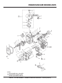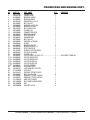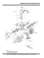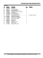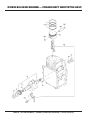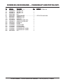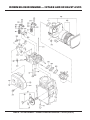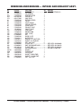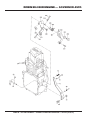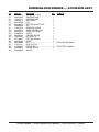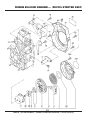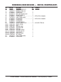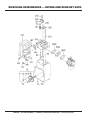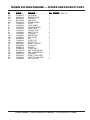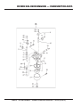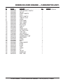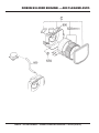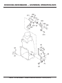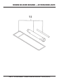
1
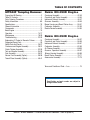
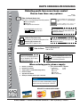
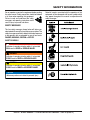
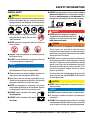
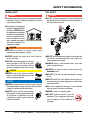
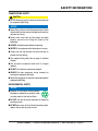
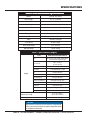
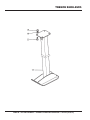
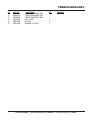
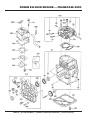
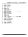
OPERATION AND PARTS MANUAL SERIES MODEL MTR40F TAMPING RAMMER (ROBIN EH090D/EH092D GASOLINE ENGINES) Revision #3 (01/05/12) To find the latest revision of this publication, visit our website at: www.multiquip.com THIS MANUAL MUST ACCOMPANY THE EQUIPMENT AT ALL TIMES. PROPOSITION 65 WARNING PAGE 2 — MTR40F RAMMER — OPERATION AND PARTS MANUAL — REV. #3 (01/05/12) NOTES MTR40F RAMMER — OPERATION AND PARTS MANUAL — REV. #3 (01/05/12) — PAGE 3 TABLE OF CONTENTS MTR40F Tamping Rammer Robin EH-090D Engine Proposition 65 Warning .............................................2 Table Of Contents .....................................................4 Parts Ordering Procedures .......................................5 Safety Information ................................................. 6-9 Specifications ..........................................................10 General Information ................................................11 Components............................................................12 Basic Engine ...........................................................13 Operation .......................................................... 14-17 Maintenance ..................................................... 18-20 Troubleshooting ................................................ 22-23 Explanation Of Codes In Remarks Column ............24 Suggested Spare Parts ...........................................25 Name Plate and Decals .................................... 26-27 Crankcase and Engine Assembly ..................... 28-31 Guide Cylinder Assembly .................................. 32-33 Tank and Handle Assembly .............................. 34-35 Foot Assembly .................................................. 36-37 Narrow Foot Assembly (Option) ....................... 38-39 Trench Shoe Assembly (Option) ....................... 40-41 Crankcase Assembly ........................................ 42-43 Crankshaft and Piston Assembly ...................... 44-45 Intake and Exhaust Assembly ........................... 46-47 Governor Assembly .......................................... 48-49 Blower Housing and Recoil Starter Assy. ......... 50-51 Carburetor Assembly ........................................ 52-53 Electric Device Assembly .................................. 54-55 Robin EH-092D Engine Crankcase Assembly ........................................ 56-57 Crankshaft and Piston Assembly ...................... 58-59 Intake and Exhaust Assembly ........................... 60-61 Carburetor Assembly ........................................ 62-63 Air Cleaner Assembly........................................ 64-65 Governor, Operation Assembly......................... 66-67 Blower Housing Assembly ............................... 68-69 Recoil Starter Assembly.................................... 70-71 Accessories Assembly ...................................... 72-73 Terms and Condition of Sale — Parts ......................... 74 NOTICE Specification and part number are subject to change without notice. PAGE 4 — MTR40F RAMMER — OPERATION AND PARTS MANUAL — REV. #3 (01/05/12) www.multiquip.com PARTS ORDERING PROCEDURES Ordering parts has never been easier! Choose from three easy options: Order via Internet (Dealers Only): Best Deal! Effective: January 1st, 2006 If you have an MQ Account, to obtain a Username and Password, E-mail us at: parts@multiquip. com. Order parts on-line using Multiquip’s SmartEquip website! ■ View Parts Diagrams ■ Order Parts ■ Print Specification Information To obtain an MQ Account, contact your District Sales Manager for more information. Use the internet and qualify for a 5% Discount on Standard orders for all orders which include complete part numbers.* Goto www.multiquip.com and click on Order Parts to log in and save! Note: Discounts Are Subject To Change Order via Fax (Dealers Only): All customers are welcome to order parts via Fax. Domestic (US) Customers dial: 1-800-6-PARTS-7 (800-672-7877) Fax your order in and qualify for a 2% Discount on Standard orders for all orders which include complete part numbers.* Note: Discounts Are Subject To Change Order via Phone: Domestic (US) Dealers Call: 1-800-427-1244 Non-Dealer Customers: Contact your local Multiquip Dealer for parts or call 800-427-1244 for help in locating a dealer near you. International Customers should contact their local Multiquip Representatives for Parts Ordering information. When ordering parts, please supply: ❒ ❒ ❒ ❒ ❒ ❒ Dealer Account Number Dealer Name and Address Shipping Address (if different than billing address) Return Fax Number Applicable Model Number Quantity, Part Number and Description of Each Part ❒ Specify Preferred Method of Shipment: ✓ UPS/Fed Ex ✓ DHL ■ Priority One ✓ Truck ■ Ground ■ Next Day ■ Second/Third Day NOTICE All orders are treated as Standard Orders and will ship the same day if received prior to 3PM PST. WE ACCEPT ALL MAJOR CREDIT CARDS! MTR40F RAMMER — OPERATION AND PARTS MANUAL — REV. #3 (01/05/12) — PAGE 5 SAFETY INFORMATION Do not operate or service the equipment before reading the entire manual. Safety precautions should be followed at all times when operating this equipment. Failure to read and understand the safety messages and operating instructions could result in injury to yourself and others. Potential hazards associated with the operation of this equipment will be referenced with hazard symbols which may appear throughout this manual in conjunction with safety messages. SAFETY MESSAGES The four safety messages shown below will inform you about potential hazards that could injure you or others. The safety messages specifically address the level of exposure to the operator and are preceded by one of four words: DANGER, WARNING, CAUTION or NOTICE. SAFETY SYMBOLS DANGER Indicates a hazardous situation which, if not avoided, WILL result in DEATH or SERIOUS INJURY. WARNING Indicates a hazardous situation which, if not avoided, COULD result in DEATH or SERIOUS INJURY. CAUTION Indicates a hazardous situation which, if not avoided, COULD result in MINOR or MODERATE INJURY. NOTICE Addresses practices not related to personal injury. PAGE 6 — MTR40F RAMMER — OPERATION AND PARTS MANUAL — REV. #3 (01/05/12) SAFETY INFORMATION GENERAL SAFETY CAUTION NEVER operate this equipment without proper protective clothing, shatterproof glasses, respiratory protection, hearing protection, steel-toed boots and other protective devices required by the job or city and state regulations. ALWAYS know the location of the nearest phone or keep a phone on the job site. Also, know the phone numbers of the nearest ambulance, doctor and fire department. This information will be invaluable in the case of an emergency. RAMMER SAFETY DANGER NEVER operate this equipment when not feeling well due to fatigue, illness or when under medication. NEVER operate this equipment under the influence of drugs or alcohol. ALWAYS check the equipment for loosened threads or bolts before starting. DO NOT use the equipment for any purpose other than its intended purposes or applications. NOTICE This equipment should only be operated by trained and qualified personnel 18 years of age and older. Whenever necessary, replace nameplate, operation and safety decals when they become difficult read. Manufacturer does not assume responsibility for any accident due to equipment modifications. Unauthorized equipment modification will void all warranties. NEVER use accessories or attachments that are not recommended by Multiquip for this equipment. Damage to the equipment and/or injury to user may result. ALWAYS know the location of the nearest fire extinguisher. ALWAYS know the location of the nearest first aid kit. NEVER operate the equipment in an explosive atmosphere or near combustible materials. An explosion or fire could result causing severe bodily harm or even death. WARNING NEVER disconnect any emergency or safety devices. These devices are intended for operator safety. Disconnection of these devices can cause severe injury, bodily harm or even death. Disconnection of any of these devices will void all warranties. DO NOT use this machine on ground that is harder than the machine can handle, or for driving pilings or tamping rock beds. Furthermore, use of the machine on sloping ground, such as the side of an embankment, may make the machine unstable and can cause an accident. It can also result in premature machine wear due to uneven loads on the machine. Use the machine with confidence for tamping earth and sand, soil, gravel, and asphalt. DO NOT use the machine for other types of jobs. CAUTION NEVER lubricate components or attempt service on a running machine. NOTICE ALWAYS keep the machine in proper running condition. Fix damage to machine and replace any broken parts immediately. ALWAYS store equipment properly when it is not being used. Equipment should be stored in a clean, dry location out of the reach of children and unauthorized personnel. MTR40F RAMMER — OPERATION AND PARTS MANUAL — REV. #3 (01/05/12) — PAGE 7 SAFETY INFORMATION ENGINE SAFETY DANGER The engine fuel exhaust gases contain poisonous carbon monoxide. This gas is colorless and odorless, and can cause death if inhaled. FUEL SAFETY DANGER DO NOT add fuel to equipment if it is placed inside truck bed with plastic liner. Possibility exists of explosion or fire due to static electricity. The engine of this equipment requires an adequate free flow of cooling air. NEVER operate this equipment in any enclosed or narrow area where free flow of the air is restricted. If the air flow is restricted it will cause injury to people and property and serious damage to the equipment or engine. WARNING DO NOT place hands or fingers inside engine compartment when engine is running. NEVER operate the engine with heat shields or guards removed. DO NOT remove the engine oil drain plug while the engine is hot. Hot oil will gush out of the oil tank and severely scald any persons in the general area of the rammer. CAUTION NEVER touch the hot exhaust manifold, muffler or cylinder. Allow these parts to cool before servicing equipment. NOTICE NEVER run engine without an air filter or with a dirty air filter. Severe engine damage may occur. Service air filter frequently to prevent engine malfunction. NEVER tamper with the factory settings of the engine or engine governor. Damage to the engine or equipment can result if operating in speed ranges above the maximum allowable. DO NOT start the engine near spilled fuel or combustible fluids. Fuel is extremely flammable and its vapors can cause an explosion if ignited. ALWAYS refuel in a well-ventilated area, away from sparks and open flames. ALWAYS use extreme caution when working with flammable liquids. DO NOT fill the fuel tank while the engine is running or hot. DO NOT overfill tank, since spilled fuel could ignite if it comes into contact with hot engine parts or sparks from the ignition system. Store fuel in appropriate containers, in well-ventilated areas and away from sparks and flames. NEVER use fuel as a cleaning agent. DO NOT smoke around or near the equipment. Fire or explosion could result from fuel vapors or if fuel is spilled on a hot engine. PAGE 8 — MTR40F RAMMER — OPERATION AND PARTS MANUAL — REV. #3 (01/05/12) SAFETY INFORMATION TRANSPORTING SAFETY CAUTION NEVER allow any person or animal to stand underneath the equipment while lifting. NOTICE Before lifting, make sure that the equipment parts (hook and vibration insulator) are not damaged and screws are not loose or missing. Always make sure crane or lifting device has been properly secured to the lifting bail (hook) of the equipment. ALWAYS shutdown engine before transporting. NEVER lift the equipment while the engine is running. Tighten fuel tank cap securely and close fuel cock to prevent fuel from spilling. Use adequate lifting cable (wire or rope) of sufficient strength. Use one point suspension hook and lift straight upwards. DO NOT lift machine to unnecessary heights. ALWAYS tie down equipment during transport by securing the equipment with rope. Never allow any person or animal to stand underneath the equipment while lifting. ENVIRONMENTAL SAFETY NOTICE Dispose of hazardous waste properly. Examples of potentially hazardous waste are used motor oil, fuel and fuel filters. DO NOT use food or plastic containers to dispose of hazardous waste. DO NOT pour waste, oil or fuel directly onto the ground, down a drain or into any water source. MTR40F RAMMER — OPERATION AND PARTS MANUAL — REV. #3 (01/05/12) — PAGE 9 SPECIFICATIONS Table1. MTR-40F Rammer Specifications MODEL MTR-40F U.S. (metric) Overall Height 43.7 in. (1,110 mm) Overall Width 13.8 in. (351 mm) Overall Length 24.5 in. (622 mm) Shoe Size 5.9 x 10.6 in. (150 x 270 mm) Blows/minute 650 ~ 699 Tamping Area 1,453 sq. ft. per hr (135 sq.m per hr) Impact Force 1,215 lbs./blow ( 550 kg/blow) Clutch Automatic Centrifugal Travel Speed 30 fpm (9 mpm) Stroke (Jump Height) 2.2 in. (55 mm) Operating Weight 101 lbs. (46 kg) Table 2. Specifications (Engine) Model Type 2.01 in. X 1.65 in. (51 mm x 42 mm) Displacement 5.24 cu. in (86 cm3) Dry Net Weight 2.4 H.P./3600 R.P.M. (1.8 kW) Fu e l Unleaded Gasoline Fuel Tank Capacity 2.1 qts (2.0 liters) Lube Oil Capacity 0.79 gal. (0.3 liters) Speed Control Method Dimension (L x W x H) Air-cooled 4 stroke, Single Cylinder, OHV, Horizontal Shaft Gasoline Engine Bore X Stroke Max Output Engine ROBIN EH090D45050/EH092D45010 Centrifugal Fly-weight Type S p a r k P lu g NKG BM6A, BMR6A Air Cleaner Dual Element Type Ignition System Flywheel Magneto (Soild State) Star ting Method Recoil Star t 9.1 x 11.6 X 13.0 in. (232 X 295 X 330 mm.) 20.7 lbs. (9.4 Kg.) NOTICE Specifications are general and are subject to change without notice. If exact measurements are required, equipment should be weighed and measured. PAGE 10 — MTR40F RAMMER — OPERATION AND PARTS MANUAL — REV. #3 (01/05/12) GENERAL INFORMATION Definition of Tamping Rammer CAUTION The Mikasa MTR40F Tamping Rammer is a powerful compacting tool capable of applying a tremendous force in consecutive impacts to a soil surface. Its applications include soil compacting for backfilling for gas pipelines, water pipelines and cable installation work. Before starting operation check the lifting handle to: The impact force of the MTR40F levels and uniformly compacts voids between soil particles to increase dry density. 1. Make sure that there is no damage on the bolts. Circular motion is converted to create impact force. The MTR40F tamping rammer develops a powerful compacting force at the foot of the rammer. To maintain optimum performance, proper operation and service are essential. 3. Make sure that there is no fissure on the surface. If there is any abnormality or damage, replace with new one. 2. Make sure that there is no crack or breakage on handle. For operation: Construction of Tamping Rammer This handle is to be used to lift up the shoe part of the machine with the body laid down on the ground or truck bed. The Mikasa MTR40F is equipped with a Robin air-cooled, fourcycle gasoline engine. Transmission of power takes place by increasing the engine speed to engage the centrifugal clutch. 1. Use proper lifting techniques to avoid back injury. This handle is for manual lifting only. Rammer Spring Cylinder and Crankcase Bearings 2. Do not use this handle as a rammer lift point. Use the lifting point on the top of the machine. The Mikasa MTR40F uses zerk grease fittings to lubricate the spring cylinder and crankcase bearings. Lubricate these grease fittings as indicated in the maintenance section of this manual. 3. Do not move the rammer with the lifting handle and the front rollers more than 16 feet (5 meters). Controls Before starting the MTR40F Tamping Rammer, identify and understand the functions of the controls. MTR40F RAMMER — OPERATION AND PARTS MANUAL — REV. #3 (01/05/12) — PAGE 11 COMPONENTS Figure 1. MTR40F Rammer Figure 1 shows the location of the controls and components for the MTR40F Tamping Rammer. The functions of each control is described below: 1. Throttle Lever — Used to adjust engine speed (rpm). Move lever forward (SLOW) to reduce engine speed, move lever back toward operator (FAST) to increase speed. 2. Fuel Shut-Off Valve — Supplies fuel from the fuel tank to the engine. To begin fuel flow move the fuel shut-off valve downward. 3. Primary Air Cleaner — Pre-cleans (first stage) dirt and other debris from entering the engine. 4. Foot — Laminated wood with tempered steel plate for superior shock absorption. 5. Grip — When transporting the rammer, carry it by griping the handle. 6. Nameplate — Displays information regarding the rammer. 7. Handle — To operate rammer GRIP handle assembly firmly on both sides. 8. Fuel Tank/Cap — Remove this cap to add unleaded gasoline to the fuel tank.Make sure cap is tightened securely. DO NOT over fill. WARNING Add fuel to the tank only when the engine is stopped and has cooled down. In the event of a fuel spill, DO NOT attempt to start the engine until the fuel residue has been completely wiped up and the area surrounding the engine is dry. 9. Engine Air Cleaner — Prevents dirt (second stage) and other debris from entering the engine. 10. Dust Sleeve — Prevents dust and debris from entering into the spring cylinder. 11. Zerk Fittings — Lubricates main springs and crankcase bearings. PAGE 12 — MTR40F RAMMER — OPERATION AND PARTS MANUAL — REV. #3 (01/05/12) BASIC ENGINE Figure 2. Engine Controls and Components INITIAL SERVICING The engine (Figure 2) must be checked for proper lubrication and filled with fuel prior to operation. Refer to the manufacturers Engine manual for instructions & details of operation and servicing. 5. Recoil Starter (pull rope) — Manual-starting method. Pull the starter grip until resistance is felt, then pull briskly and smoothly. 1. 6. Muffler — Used to reduce noise and emissions. Secondary Air Cleaner — Prevents dirt and other debris from entering the fuel system. Remove wing-nut on top of air filter cannister to gain access to filter element. WARNING Engine components can generate extreme heat.To prevent burns, DO NOT touch these areas while the engine is running or immediately after operating. NEVER operate the engine with the muffler removed. 2. Choke Lever — Used when starting the engine. Normally used in cold weather conditions. In cold weather turn the choke lever to the fully closed position, in warm weather set choke lever half way or completely open. 3. Spark Plug — Provides spark to the ignition system. Set spark plug gap to 0.02 - 0.03 inch (0.6 - 0.7 mm). Clean spark plug once a week. 7. Engine ON/OFF Switch — Controls the starting and stopping of the engine. Switch must be in the "ON" position when starting the engine. Dipstick/Oil Filler Cap — Remove this cap to determine if the engine oil is low. Add oil through this filler port as recommended in Table 3. 8. Oil Drain Plug — Remove this plug to remove oil from the engine's crankcase. 4. NOTICE Operating the engine without an air filter, with a damaged air filter, or a filter in need of replacement will allow dirt to enter the engine, causing rapid engine wear. MTR40F RAMMER — OPERATION AND PARTS MANUAL — REV. #3 (01/05/12) — PAGE 13 INSPECTION This section is intended to assist the operator with the inspection of the MTR40F Tamping Rammer. It is extremely important that this section be read carefully before attempting to operate the rammer. Fuel DO NOT use your rammer until this section is thoroughly understood. 2. Inspection ■ Check all nuts, bolts fasteners for tightness. Retighten as necessary. 1. This rammer is equipped with a two-cycled gasoline engine. Use only unleaded gasoline. High test ethyl gasoline is not recommended. If fuel is low, remove the fuel filler cap (Figure 4) and fill with only unleaded gasoline. Motor fuels are highly flammable and can be dangerous if mishandled. DO NOT smoke while refueling. DO NOT attempt to refuel the rammer if the engine is hot! or running. ■ Clean any dirt from the recoil starter and engine cooling fins. Wipe the entire rammer clean before operating. ■ Replace any missing or damaged Safety Operation decals. CAUTION DO NOT attempt to operate the Tamping Rammer until the Safety, General Information and Inspection sections of this manual have been read and thoroughly understood. Figure 4. Fuel Tank Prior to Operation 1. When transporting the rammer, carry it by the grip handle located on the body (Figure 3). Engine Oil Check 1. To check the engine oil level, place the rammer on secure level ground with the engine stopped. 2. Remove the filler cap/dipstick from the engine oil filler hole (Figure 5) and wipe it clean. Figure 3. Grip Handle Figure 5. Engine Oil Dipstick Main Spring and Crankcase Lubrication 1. There are 2 grease fittings (Figure 18) that require lubrication of the main springs. Lubricate these fittings as outlined in the maintenance section of this manual. 2. There are 2 grease fittings (Figure 19) that require lubrication of the crankcase. Lubricate these fittings as outlined in the maintenance section of this manual. 3. Insert and remove the dipstick without screwing it into the filler neck. Check the oil level shown on the dipstick. 4. If the oil level is low (Figure 6), fill to the edge of the oil filler hole with the recommended oil type (Table 3). Maximum oil capacity is .079 gallons (0.3 liters). PAGE 14 — MTR40F RAMMER — OPERATION AND PARTS MANUAL — REV. #3 (01/05/12) INSPECTION Figure 6. Engine Oil Dipstick (Oil Level) Table 3 Motor Oil Grade Season or Temperature Grade of motor oil (higher than MS class) Spring, Summer or Autumn +120° F to +15° F SAE 30 Winter +40° F to +15° F SAE 30 Below +15° F SAE 10W-30 Inspection 1 . Check all nuts, bolts fasteners for tightness. Retighten as necessary. 2. Clean any dirt from the recoil starter and foot pedestal. Wipe the entire unit clean before operating. 3. Replace any missing or damaged Safety Operation decals. 4. Adjust height of handle. Adjust handle by loosening nuts and moving handle to suit operation. Retighten nuts. MTR40F RAMMER — OPERATION AND PARTS MANUAL — REV. #3 (01/05/12) — PAGE 15 OPERATION Operation The following steps outline the procedure for starting the engine: 1. Open the fuel shut- off valve by moving the fuel cock lever to the open position (Figure 7). 4. In cold weather, start the unit with choke lever "Fully Closed" (Figure 10). In warm weather or when the engine is warm, the unit can be started with choke halfway or completely open. Figure 10. Choke Lever (Closed) 5 Figure 7. Fuel Shut-Off Valve (Open) 2. Grip the recoil starter (Figure 11) handle and pull it until you feel a slight resistance. Then pull sharply and quickly. Return the recoil starter handle to the starter position before releasing. Set the engine ON/OFF switch (Figure 8) to the "ON" position (start). Figure 8. ON/OFF Switch (ON Position) 3. Move the throttle lever to the "IDLE" position (Figure 9). Figure 11. Recoil Starter 6. If engine fails to start, move the choke lever (Figure 10) to the half open position to avoid flooding. 7. Repeat steps 1 through 6. 8. If the engine does not start after repeated attempts, check the spark plug for excess fuel. Clean and replace the spark plug as needed. Figure 9. Throttle Lever (Idle) PAGE 16 — MTR40F RAMMER — OPERATION AND PARTS MANUAL — REV. #3 (01/05/12) OPERATION Operation 1. To start the rammer tamping action, move the throttle lever (Figure 12) quickly from IDLE (close) to the FULL OPEN position. DO NOT move the throttle lever slowly as this may cause damage to the clutch or spring. 2. After the engine cools, turn the engine ON/OFF switch to the “OFF” position (Figure 14). Figure 14. ON/OFF Switch (Off Position) 3. Close the fuel shut- off valve (Figure 15) by moving the fuel cock lever to the CLOSED position. Figure 12. Throttle Lever (Full Open) CAUTION Make sure that the throttle lever is moved to the FULL OPEN position. Operating the rammer at less than full speeds can result in damage to the clutch springs or foot. 2. The MTR40F tamping rammer is designed to run between 3,800~4,100 rpms. At optimum rpm the foot hits at the rate of 650~695 impacts per minute. Increasing throttle speed past factory set rpm does not increase impacts and may damage unit.The MTR40F is designed to advance while tamping. For faster advance, pull back slightly on the handle so that rear of foot contacts soil first. Stopping The Engine Normal Shutdown 1. Move throttle lever quickly from the FULL OPEN to IDLE position (Figure 13 ) and run the engine for three minutes at low speed. Figure 15. Fuel Shut-Off Valve (Closed Position) Emergency Showdown 1. Move the throttle lever quickly to the IDLE position, and turn the engine ON/OFF switch to the OFF position. Turn the fuel valve lever to the CLOSED position. Figure 13. Throttle Lever (Idle) MTR40F RAMMER — OPERATION AND PARTS MANUAL — REV. #3 (01/05/12) — PAGE 17 MAINTENANCE Maintenance Perform the scheduled maintenance procedures as defined by Table 4 and below: Daily ■ Thoroughly remove dirt and oil from the engine compartment and rammer. Clean or replace the air cleaner elements as necessary. Check and retighten all fasteners as necessary. Check the bellows for oil leaks. Repair or replace as needed. 200 - 300 HOURS (Pre-Cleaner) ■ Remove the element from the pre-cleaner (Figure 16) at the top of the crankcase (body side) and clean it with cleaning oil (kerosene). BREATHER ELEMENT PAPER ELEMENT GRAY OUTER FOAM ELEMENT CLEAN WITH KEROSENE CLEAN WITH SOLVENT Figure 17. Engine Air Cleaner Main Springs Lubrication ■ The rammer main springs (Figure 18) should be lubricated with five shots of grease with a hand grease gun after each eight (8) hours of use. ■ Use MQ HIGH TEMPERATURE GREASE, P/N GRS2 or its equivalent. ■ Equivalent greases include Shell Darina or Texaco Thermatex, both of which have a bentone base and EP-2 rating. Figure 16. Primary Air Cleaner ■ If an inferior grease is used, it may become too thick or too thin due to changes in temperature, and improper lubrication could result. ■ Lubricate the top element (yellow) with 2~5 cc of engine oil SAE-30. ■ Lubricate bottom element (gray) with 7~9 cc of engine oil SAE-30 and completely squeeze out the excess oil from the element before installing. Air Cleaner ■ The air cleaner (Figure 17) should be inspected and cleaned on a regular basis at least once a week. Remove element, rinse in soapy water, squeeze and allow to air dry until completely dry before reinstalling. ■ Carefully tap the paper filter element (Figure 17) several times on a hard surface until all dirt is removed then reinstall. NEVER brush off dirt. Brushing will force dirt into the fibers. Replace the paper filter element if it is excessively dirty. Figure 18. Grease Fittings (Main Springs) PAGE 18 — MTR40F RAMMER — OPERATION AND PARTS MANUAL — REV. #3 (01/05/12) MAINTENANCE Crankcase Lubrication ■ The rammer crankcase bearings (Figure 19) should be lubricated with five shots of grease with a hand grease gun after each eight (8) hours of use. Spark Plug ■ Remove and clean the spark plug (Figure 20), then adjust the spark gap to 0.024 ~0.028 inch (0.6~0.7 mm). This unit has electronic ignition, which requires no adjustments. ■ Use MQ HIGH TEMPERATURE GREASE, P/N GRS2 or its equivalent. Figure 20. Spark Plug Gap Long Term Storage ■ Drain fuel from fuel tank, fuel line and carburetor. Figure 19. Grease Fittings (Crankcase) Fuel Lines ■ Check the fuel and oil lines regularly for damage and ensure that there are no leaks. ■ Replace the fuel lines every two years to maintain the performance and flexibility of the fuel lines. Cleaning the Rammer ■ If using a high pressure spray washer, be careful not to splash water directly on the air cleaner, carburetor, muffler, and fuel cap. Excessive amounts of water may cause severe engine damage. ■ Remove spark plug and pour a few drops of motor oil into cylinder. Crank engine 3 to 4 times so that oil reaches all internal parts. ■ Clean exterior of rammer with an oil-moistened cloth. ■ Store unit covered with plastic sheet in moisture free and dust free location out of direct sunlight. NOTICE Refer to manufacturer engine manual for specific servicing instructions. MTR40F RAMMER — OPERATION AND PARTS MANUAL — REV. #3 (01/05/12) — PAGE 19 MAINTENANCE Perform the scheduled engine maintenance procedures as defined by Table 4 below: Table 4. Engine Maintenance Schedule DESCRIPTION (3) OPERATION BEFORE CHECK X FIRST EVERY MONTH 3 MONTHS OR OR 10 HRS. 25 HRS. EVERY 6 MONTHS OR 50 HRS. EVERY Y E AR OR 100 HRS. EVERY 2 YEARS OR 200 HRS. Engine Oil CHANGE CHECK X X Air Cleaner CHANGE All Nuts & Bolts Re-tighten If Necessary X (1) X CHECK-CLEAN X Spark Plug REPLACE X Cooling Fins CHECK X Spark Arrester CLEAN X Fuel Tank CLEAN X Fuel Filter CHECK X Idle Speed CHECK-ADJUST X (2) Valve Clearance CHECK-ADJUST Fuel lines CHECK X (2) Every 2 years (replace if necessary) (2) (1) Service more frequently when used in DUSTY areas. (2) These items should be serviced by your servic dealer, unless you have the proper tools and are mechanically proficient. Refer to the ROBIN shop Manual for service procedures (3) For commercial use, log hours of operation to determine proper maintenance intervals. PAGE 20 — MTR40F RAMMER — OPERATION AND PARTS MANUAL — REV. #3 (01/05/12) NOTES MTR40F RAMMER — OPERATION AND PARTS MANUAL — REV. #3 (01/05/12) — PAGE 21 TROUBLESHOOTING TABLE 5. ENGINE TROUBLESHOOTING SYMPTOM POSSIBLE PROBLEM SOLUTION Difficult to start Fuel is available but spark plug will not ignite. (Power available at high tension cable). Fuel is available but spark plug will not ignite. (Power NOT available at high tension cable). Fuel is available and spark plug ignites (compression normal). Fuel is available and spark plug ignites (compression low ). Ignition plug being bridge? Check ignition system. Carbon deposit at ignition? Clean or replace ignition. Shor t circuit due to defective insulators? Replace insulators. Improper spark gap? Set spark plug gap to the correct gap. Shor t circuit at stop switch? Check stop switch circuit. Replace stop switch if defective. Ignition coil defective? Replace ignition coil. Muffler clogged with carbon deposits? Clean or replace muffler. Mixed fuel quality is inadequate? Check fuel to oil mixture. Fuel in use inadequate (water, dust)? Flush fuel sytem and replace with fresh fuel. Air Cleaner clogged? Clean or replace air cleaner. Defective cylinder head gasket? Tighten cylinder head bolts or replace head gasket. Cylinder worn? Replace cylinder. Spark plug loose? Tighen spark plug. Air cleaner clogged? Clean or replace air cleaner. Air in fuel line? Bleed (remove air) from fuel line. Fuel level in carbureator float chamber improper? Adjust carbureator float Carbon deposits in cylinder? Clean or replace cylinder Ignition coil defective? Flush fuel sytem and replace with fresh fuel. Ignition plug often shor ts? Replace ignition wires, clean ignition. Fuel in use inadequate (water, dust)? Flush fuel sytem and replace with fresh fuel. Mixed fuel quality is inadequate? Check fuel to oil mixture. Excessive carbon depostion in combustion chamber? Clean or replace crankcase. Exhaust or muffler clogged with carbon. Clean or replace muffler. Spark plug heat value incorrect? Replace spark plug with correct type spark plug. Operation not satisfactory Not enough power available (compression normal, no missfiring). Not enough power available (compression normal, missfiring). Engine overheats. PAGE 22 — MTR40F RAMMER — OPERATION AND PARTS MANUAL — REV. #3 (01/05/12) TROUBLESHOOTING ENGINE TABLE 5. ENGINE TROUBLESHOOTING (continued) SYMPTOM POSSIBLE PROBLEM SOLUTION Operation not satisfactory Rotational speed fluctuates. Recoil star ter not working properly. Governor adjustment improper? Adjust governor to correct lever. Governor spring defective? Clean or replace ignition. Fuel flow erratic? Check fuel line. Air taken in through suction line? Check suction line. Dust in rotating par t? Clean recoil star ter assembly. Spring spring failure? Replace spiral spring. TABLE 6. RAMMER TROUBLESHOOTING SYMPTOM Engine rotates but amplituide not uniform or does not strike. POSSIBLE PROBLEM SOLUTION Operating speed of throttle lever is incorrectly set? Set throttle lever to correct position. Clutch slips? Replace or adjust clutch. Spring Failure? Replace sprial spring. Speed of engine improper? Adjust engine speed to correct operating RPM setting. MTR40F RAMMER — OPERATION AND PARTS MANUAL — REV. #3 (01/05/12) — PAGE 23 EXPLANATION OF CODES IN THE REMARKS COLUMN The following section explains the different symbols and remarks used in the Parts section of this manual. Use the help numbers found on the back page of the manual if there are any questions. NOTICE The contents and part numbers listed in the parts section are subject to change without notice. Multiquip does not guarantee the availability of the parts listed. SAMPLE PARTS LIST NO. 1 2% 2% 3 4 PART NO. PART NAME QTY. REMARKS 12345 BOLT......................1 .....INCLUDES ITEMS W/% WASHER, 1/4 IN............NOT SOLD SEPARATELY 12347 WASHER, 3/8 IN....1 .....MQ-45T ONLY 12348 HOSE ..................A/R ...MAKE LOCALLY 12349 BEARING ..............1 .....S/N 2345B AND ABOVE NO. Column QTY. Column Numbers Used — Item quantity can be indicated by a number, a blank entry, or A/R. A/R (As Required) is generally used for hoses or other parts that are sold in bulk and cut to length. A blank entry generally indicates that the item is not sold separately. Other entries will be clarified in the “Remarks” Column. REMARKS Column Some of the most common notes found in the “Remarks” Column are listed below. Other additional notes needed to describe the item can also be shown. Assembly/Kit — All items on the parts list with the same unique symbol will be included when this item is purchased. Unique Symbols — All items with same unique symbol Indicated by: “INCLUDES ITEMS W/(unique symbol)” (@, #, +, %, or >) in the number column belong to the same assembly or kit, which is indicated by a note in the “Remarks” column. Serial Number Break — Used to list an effective serial number range where a particular part is used. Duplicate Item Numbers — Duplicate numbers indicate multiple part numbers, which are in effect for the same general item, such as different size saw blade guards in use or a part that has been updated on newer versions of the same machine. NOTICE When ordering a part that has more than one item number listed, check the remarks column for help in determining the proper part to order. PART NO. Column Numbers Used — Part numbers can be indicated by a number, a blank entry, or TBD. TBD (To Be Determined) is generally used to show a part that has not been assigned a formal part number at the time of publication. A blank entry generally indicates that the item is not sold separately or is not sold by Multiquip. Other entries will be clarified in the “Remarks” Column. Indicated by: “S/N XXXXX AND BELOW” “S/N XXXX AND ABOVE” “S/N XXXX TO S/N XXX” Specific Model Number Use — Indicates that the part is used only with the specific model number or model number variant listed. It can also be used to show a part is NOT used on a specific model or model number variant. Indicated by: “XXXXX ONLY” “NOT USED ON XXXX” “Make/Obtain Locally” — Indicates that the part can be purchased at any hardware shop or made out of available items. Examples include battery cables, shims, and certain washers and nuts. “Not Sold Separately” — Indicates that an item cannot be purchased as a separate item and is either part of an assembly/kit that can be purchased, or is not available for sale through Multiquip. PAGE 24 — MTR40F RAMMER — OPERATION AND PARTS MANUAL — REV. #3 (01/05/12) SUGGESTED SPARE PARTS MTR40F RAMMER 3 TO 5 UNITS WITH ROBIN EH-09D45050/EH-092D45010 ENGINES Qty. P/N Description 1 ............ 362910060 ............ LEVER, THROTTLE 1 ............ 956100040 ............ THROTTLE WIRE 3 ............ 362030030 ............ ELEMENT, AIR CLEANER 5 ............ 362030020 ............ PACKING, AIR CLEANER 3 ............ 362455670 ............ ELEMENT, CRANKCASE 1 ............ 361910021 ............ CAP, FUEL TANK W/ STRAP 1 ............ 954300720 ............ COCK, FUEL ASSY. 2 ............ 301419750 ............ FILTER, IN-LINE FUEL 3 ............ 2743260307 .......... ELEMENT, SET ENGINE 1 ............ 0660000361 .......... STOP, SWITCH 3 ............ 0650140470 .......... SPARK PLUG, NKG 1 ............ 362454441 ............ CLUTCH 3 ............ 2745011108 .......... STARTER ROPE 1 ............ 954404890 ............ FILTER, FUEL TANK (UPPER) 1 ............ 954406010 ............ STRAINER, FUEL TANK (LOWER) NOTICE Part number on this Suggested Spare Parts List may supersede/replace the P/N shown in the text pages of this book. MTR40F RAMMER — OPERATION AND PARTS MANUAL — REV. #3 (01/05/12) — PAGE 25 NAMEPLATE AND DECALS 1 2 16 GASOLINE ONLY NPA 1017 J Before Operation To start, switch must be in the “ON” position Check all nuts and bolts for tightness Keep machine at the upright operating position to check NPA 293 J 1. Give each grease fitting five (5) shots of grease with a hand grease gun. 2. Check the engine oil level and if the level is low, it should be refilled from the filler hole. To STOP engine: 15 13 5 Oil öl NPA-961 E Open fuel filter valve and close choke lever on carburetor. Place starter switch to “ON” and pull start rope. When engine starts, open the choke lever and warm up the engine for 4-5 minutes before operation. Then move throttle lever from “OFF” to “ON” to operate. Move the throttle lever quickly from “ON” to “OFF” position. Then move starter lever quickly to “OFF” and close the fuel filter valve. NPA-1100 J 12 OPERATION To START engine: Gasoline Only Bitte nur Benzine einfüllen Essence Uniquement Usare solo Benzina Solo para Gasolina 4 I’ huile SAE30 7~9 cc NPA-896 J 3 3800 ~ 4100 RPM NPA-910 J NPA-957 J When you stop the engine, be sure to close the fuel cock 6 NPA-399 J 18 14 MTR-40F CAUTION ATTENZIONE ATENÇAÕ PRECAUCION Read operator’s manual carefully before use. Lire le manuel attentivement avant utilisation. Bitte lesen Sie vor lnbetriebnahme der Maschine die bedienungsanleitung sorgältig durch. Prima delÍ uso leggere attentamente il manuale. Lee com atenÇão manual de instruÇõ antes de usar. Leer detenidamente el manual de instrucciones antes de usar la maquina. NPA-769 J SECONDARY AIRFILTER SERVICE MONTHLY 9 7 NAMEPLATE READ OWNER’S SERVICE MANUAL BEFORE OPERATING OR SERVICING THIS MACHINE. ALWAYS KEEP UNAUTHORIZED, INEXPERIENCED, UNTRAINED PEOPLE AWAY FROM THIS MACHINE. 11 MAKE SURE ALL SAFETY DEVICES ARE OPERATIONAL BEFORE THIS MACHINE IS STARTED. MAKE SURE ENGINE IS TURNED OFF AND SPARK PLUG WIRE DISCONNECTED BEFORE SERVICING THE MACHINE OR COMING IN CONTACT WITH ANY MOVING PART. IF EQUIPMENT IS POWERED BY AN ELECTRIC MOTOR DISCONNECT ELECTRICAL PLUG. PRIMARY AIRFILTER CHECK DAILY 17 NPA 1016 J CLEAN THE ELEMENT WITH KEROSENE WHEN DIRTY. AFTER THE CLEANING, LUBRICATE IT MIXED OIL (KEROSENE 2~4: ENGINE OIL 1), SQUEEZE OUT THE OIL, AND REPLACE IT. AND CLEAN IT MORE OFTEN WHEN OPERATING IN DUSTY CONDITIONS. NPA-831 J NEVER LEAVE MACHINE UNATTENDED WHEN OPERATING. ALWAYS STOP ENGINE AND ALLOW ENGINE TO COOL BEFORE ADDING FUEL OR OIL. NPA 1018 J NPA-329 J LAY DOWN TOWARD THIS DIRECTION ONLY 8 NPA-963 J CLEANING ELEMENT: Remove the element from the pre-cleaner Clean the element with solvent Apply SAE30 motor oil with 7~9 cc, and squeeze out excess oil before re-installing. GREASE NPA-120 J 10 PAGE 26 — MTR40F RAMMER — OPERATION AND PARTS MANUAL — REV. #3 (01/05/12) NAMEPLATE AND DECALS NO PART NO PART NAME 1 2 3 4 5 6 7 8 9 10 11 12 13 14 15 16 17 18 NPA1017 NPA1100 920203990 NPA957 NPA896 NPA1016 920203290 920209630 920209910 920101200 NPA1018 920209100 920209610 NPA831 920100240 920202930 NPA691 NPA769 DECAL: GASOLINE ONLY DECAL: CAUTION (OPERATION) DECAL: CAUTION (FUEL COCK) DECAL: ENGINE RPM DECAL: ELEMENT SET DECAL: SECONDARY AIR FILTER DECAL: CAUTION DECAL: CLEANING ELEMENT PLATE: SERIAL NO. ............................... DECAL: GREASE DECAL: PRIMARY AIR FILTER DECAL: RAMMER BOOT & HEARING DECAL: DECAL OIL 7-9 CC DECAL: CAUTION/OIL INJECT DECAL: (M-MARK) DECAL: SWITCH-ON DECAL: LAYDOWN DECAL: CAUTION QTY. REMARKS 1 1 1 1 1 1 1 1 1 .............. CONTACT MQ PARTS DEPT. 3 1 1 1 1 1 1 1 1 MTR40F RAMMER — OPERATION AND PARTS MANUAL — REV. #3 (01/05/12) — PAGE 27 CRANKCASE AND ENGINE ASSY. PAGE 28 — MTR40F RAMMER — OPERATION AND PARTS MANUAL — REV. #3 (01/05/12) CRANKCASE AND ENGINE ASSY. NO PART NO PART NAME QTY. REMARKS 1 305117260 CRANK CASE 1 2 305343780 CRANK GEAR 1 CLUTCH GUIDE / A 3 041006305 BEARING 6305Z 1 45 0053204201 WOODRUFF KEY 1 4 041006203 BEARING 6203Z 1 46 301010210WASHER LOCK CLUTCH 11 5 952401450 8.5 xWASHER 22 x 3 6 001220825 8 x 25 T 47 956300130BOLT THROTTLE LEVER AY 25 1 7 030208200 WASHER, LOCK M8 1 9 362455660 BEARING COVER 1 10 002210620 BOLT 6X20 H,SW 2 11 050100350 O-RING G-35 1 13 305333090 CONNECTING ROD 1 14 042006304 BEARING 6304ZZ 1 15 080100520 STOP RING R-52 1 16 952400130 WASHER 9304 1 17 001220825 BOLT 8 x 25 T 1 18 030208200 WASHER, LOCK M8 1 20 303010084 PINION 1 21 042006007 BEARING 6007ZZ 2 22 351437750 SPACER 35.4-42.7-11 1 23 080200350 STOP RING S-35 1 24 351421900 SPACER, CLUTCH DRUM 1 25 060504010 OIL SEAL VB-40525 1 26 050300900 O-RING S-90 1 27 362454441 CLUTCH ASSY. CE120P 1.6T ........................... 1 ........... INCLUDES ITEMS W/ * 27-1 943020020 CLUTCH SHOE C812 4 * 27-2 943050050 CLUTCH BOSS C812 1 27-3* 943060100 CLUTCH GUIDE (A) 1 27-4* 943060020 CLUTCH GUIDE (B) 1 27-5* 943030021 CLUTCH SPRING 2 28 * 0053204201 WOODRUFF KEY 1 29 301010210 LOCK WASHER, CLUTCH 1 30* 0173120010 LOCK NUT 1 32 362341610 PACKING, FRONT COVER 1 33 002200620 BOLT 6 x 20 H,SW 9 34 351010050 GREASE FITTING A-MT6X1 1 35 351010320 GREASE FITTING B-MT6X1 1 37 2741500123 ADAPTER FLANGE 1 38 0011408400 BOLT AND WASHER ASSY. 4 39 0021808000 NUT 4 40 0032008000 WASHER, LOCK 4 MTR40F RAMMER — OPERATION AND PARTS MANUAL — REV. #3 (01/05/12) — PAGE 29 CRANKCASE AND ENGINE ASSY. PAGE 30 — MTR40F RAMMER — OPERATION AND PARTS MANUAL — REV. #3 (01/05/12) CRANKCASE AND ENGINE ASSY. CONTINUED NO PART NO PART NAME 41 42 63 64 65 66 67 68 69 71 71-1# 71-2# 71-3# 71-4# 72 73 74 75 81 86 WASHER 4 DOWEL PIN 2 CLIP (TCP-10509B) 1 OIL GAUGE PROTECTOR 1 LINK PROTECTOR 1 BOLT 8X20 W/FLAT/LOCK WASHER 4 STIFFENER 1 BOLT AND WASHER 4 BOLT AND WASHER ASSY. 2 AIR CLEANER ASSY. ........................................ 1 ........... INCLUDES ITEMS W/# COVER CP, AIR CLEANER 1 PACKING, AIR CLEANER 1 ELEMENT CP, AIR CLEANER 1 BOLT CP, AIR CLEANER 1 INTAKE PIPE 1 CLAMP TC-200 2 O-RING (7) 1 WASHER, FLAT M8 1 FRONT COVER 1 ENGINE ASSY., EH09D 0031108000 0310060020 959006120 362341620 362341630 002400820 2741600113 0011408250 0011408300 362116871 362030011 362030020 362030030 362030040 353342400 507010110 050300070 031108160 306010020 911210905 QTY. REMARKS MTR40F RAMMER — OPERATION AND PARTS MANUAL — REV. #3 (01/05/12) — PAGE 31 GUIDE CYLINDER ASSY. PAGE 32 — MTR40F RAMMER — OPERATION AND PARTS MANUAL — REV. #3 (01/05/12) GUIDE CYLINDER ASSY. NO PART NO PART NAME 1 2 3 4 6 7 8 9 11 12 13 14 15 16 18 19 20 21 22 23 25 26 305446380 080100120 305337980 305451550 305446400 305446410 305446420 305212710 305112730 065105010 080510680 351010050 305446430 001220816 305446440 001520815 305446450 305446460 011208030 020308060 050100800 002211025 PISTON PIN STOP RING R-12 PISTON ROD,M14 PISTON END, M14 STOPPER, UPPER CYLINDER CAP MAIN SPRING SPRING CYLINDER GUIDE CYLINDER DUST SEAL DKI-5367811 STOP RING TH-R-68 GREASE FITTING A-MT6x1 STOPPER BOLT 8x15 H, SW GRIP SOCKET HEAD BOLT 8x15 T DUST SLEEVE SLEEVE BAND BOLT 8x30 NUT M8 O-RING G-80 BOLT 10x25 H, SW QTY. REMARKS 1 2 1 1 1 1 2 1 1 1 1 2 1 4 1 2 1 1 1 1 1 4 MTR40F RAMMER — OPERATION AND PARTS MANUAL — REV. #3 (01/05/12) — PAGE 33 TANK AND HANDLE ASSY. PAGE 34 — MTR40F RAMMER — OPERATION AND PARTS MANUAL — REV. #3 (01/05/12) TANK AND HANDLE ASSY. NO PART NO 1 2 3A 3B 4 5 6 7 9# 10 11 17# 18# 19 20# 21 22 23 24 31# 32 32 33 33 34 41# 43 44 45* 47* 48* 49* 50* 51* 52* 53* 54* 55 56 57* 58* 59* 60 61 306117960 HANDLE 1 351319900 SHOCK ABSORBER 2 009110007 SOCKET HEAD BOLT 10x20 T 4 033121009 TOOTHED LOCKWASHER B M10 4 002211020 BOLT 10x20 H, SW 4 939010210 STOPPER RUBBER EH1002 1 030208200 WASHER, LOCK M8 1 020308060 NUT M8 1 361910021 TANK CAP CP (ORANGE) 1 305910032 FUEL TANK ASSY. ...................................... 1 ............ 361455740 SUB CAP 1 351437785 HOLDER, COCK 1 954406020 PACKING, FUEL TANK 1 954300720 FUEL COCK ASSY./CVL-08 1 954406010 STRAINER (#110) 1 001220830 BOLT 8x30 T 2 030208200 WASHER, LOCK M8 2 022710809 NYLON NUT M8 2 952401450 WASHER 8.5x22x3 2 954404890 FILTER, TANK 1 954403030 ........... HOSE BAND (8) .......................................... 4 ............ 0561080020 ......... HOSE CLAMP ............................................. 4 ............ 351436350 ........... FUEL HOSE, L=150 .................................... 2 ............ 0851041790 ......... FUEL HOSE FOR EVP, L=150 .................... 2 ............ 301419750 FUEL FILTER CP 1 362116890 F. TANK 2L (GRAY) 1 362910060 THROTTLE LEVER ASSY. .......................... 1 ............ 362341550 THROTTLE BODY 1 362910090 THROTTLE, GEAR CP. W/ BOLT 1 362455620 SLIDER 1 362455630 THROTTLE LEVER 1 050100450 O-RING G-45 1 050200100 O-RING P-10 1 031110160 WASHER, FLAT M10 3 033910070 CONICAL SPRING WASHER 2 096206006 SOCKET HEAD SCREW 6 x 6 1 022131008 CAP NUT M10 1 020410060 NUT M10, H=6 1 096208020 SOCKET HEAD SCREW 8 x 20 1 020408050 NUT M8, H=5 2 956100040 THROTTLE WIRE 620-710 1 001220620 BOLT 6X20 T 2 030206150 WASHER, LOCK 2 022130605 CAP NUT M6 2 PART NAME QTY. REMARKS INCLUDES ITEMS W/ # S/N S-3129 AND BELOW S/N S-3130 AND ABOVE S/N S-3129 AND BELOW S/N S-3130 AND ABOVE INCLUDES ITEMS W/ * MTR40F RAMMER — OPERATION AND PARTS MANUAL — REV. #3 (01/05/12) — PAGE 35 FOOT ASSY. (OPTION) PAGE 36 — MTR40F RAMMER — OPERATION AND PARTS MANUAL — REV. #3 (01/05/12) FOOT ASSY. (OPTION) NO PART NO PART NAME 30 31 32* 33* 34* 35* 36* 37* 38 39 305910010 305333120 305333130 305446470 015110055 022711012 030210250 015112075 022711214 030212300 FOOT ASSY. 150B ....................... 1 .......... INCLUDES ITEMS W/ * FOOT 150B 1 METAL SHEET 150B 1 FOOT COVER 1 SUNK HEAD BOLT 10x50 H 2 NYLON NUT M10 2 WASHER, LOCK M10 2 SUNK HEAD BOLT 12x60 H 4 NYLON NUT M12 4 WASHER, LOCK M12 4 QTY. REMARKS MTR40F RAMMER — OPERATION AND PARTS MANUAL — REV. #3 (01/05/12) — PAGE 37 NARROW FOOT ASSY. (OPTION) PAGE 38 — MTR40F RAMMER — OPERATION AND PARTS MANUAL — REV. #3 (01/05/12) NARROW FOOT ASSY. (OPTION) NO PART NO PART NAME A A 1 1* # 2 2* # 3 3* # 4 # 5*# 6*# 7* 8 9 305910020 305910040 305333140 305334930 305333150 305334940 305446470 305447810 001611050 022711012 030210250 001611252 022711214 030212300 FOOT ASSY. 200B ........................................ 1 ........... INCLUDES ITEMS W/ FOOT ASSY. 100B ........................................ 1 ........... INCLUDES ITEMS W/#* FOOT 200B ................................................... 1 ........... 200B FOOT 100B ................................................... 1 ........... 100B METAL SHEET 200B .................................... 1 ........... 200B METAL SHEET 100B .................................... 1 ........... 100B FOOT COVER ............................................... 1 ........... 200B FOOT COVER 96B ....................................... 1 ........... 100B SUNK HEAD BOLT 10x50 H 2 NYLON NUT M10 2 WASHER, LOCKM10 2 SUNK HEAD BOLT 12x60 H 4 NYLON NUT M12 4 WASHER, LOCK M10 4 QTY. REMARKS MTR40F RAMMER — OPERATION AND PARTS MANUAL — REV. #3 (01/05/12) — PAGE 39 TRENCH SHOE ASSY. PAGE 40 — MTR40F RAMMER — OPERATION AND PARTS MANUAL — REV. #3 (01/05/12) TRENCH SHOE ASSY. NO PART NO 11 11 11 12 13 14 305333160 305333170 305334390 001221235 020312100 030212300 PART NAME TRENCH SHOE 500H-120B TRENCH SHOE 800H-120B TRENCH SHOE 305H-100B BOLT 12x35 T NUT M12 WASHER, LOCK M12 QTY. REMARKS 1 1 1 4 4 4 MTR40F RAMMER — OPERATION AND PARTS MANUAL — REV. #3 (01/05/12) — PAGE 41 ROBIN EH-090D ENGINE — CRANKCASE ASSY. PAGE 42 — MTR40F RAMMER — OPERATION AND PARTS MANUAL — REV. #3 (01/05/12) ROBIN EH-090D ENGINE — CRANKCASE ASSY. NO PART NO PART NAME 10 20% 26 30# 40# 50# 60% 61% 62% 70% 75# 80 90 150 160 210 220 230 250 260 265 270 280 300 610 620 630 680 690 700 710 727 820 821 825 850 850-1 852 860 960 2741010121 2371420203 2371600801 0440200070 0600200140 0310060020 0013906600 0105060200 0105060170 0105060160 0440060010 0401140030 0211140020 2741600113 0011408250 2741100131 0440200110 0600200140 2304500301 2054190103 0013908500 2306360113 0213160020 0130060200 2741300131 2741550103 0110080210 2741550223 2741600403 0310060020 0011406600 0566000250 2741440101 2741620103 2741440503 2741610203 0566000331 0569000010 0011305100 2749900107 CRANKCASE CP .................................... 1 ..........INCLUDES ITEMS W/# VALVE GUIDE 2 STEM SEAL CP 1 OIL SEAL 20X32X6 1 BALL BEARING 1 DOWEL PIN 2 STUD 1 STUD 1 STUD 2 STUD 2 OIL SEAL 6X10X2.5 1 PLUG 1 GASKET 1 STIFFENER 1 BOLT & WASHER 2 MAIN BEARING COVER ......................... 1 ..........INCLUDES ITEMS W/ OIL SEAL 20X32X6 1 BALL BEARING 1 GOVERNOR GEAR CP 1 GOVERNOR SLEEVE 1 STUD 4 OIL GAUGE 1 GASKET 1 BOLT & WASHER 9 CYLINDER HEAD CP ............................. 1 ..........INCLUDES ITEMS W/% GASKET, HEAD 1 FLANGE BOLT 4 ROCKER COVER 1 GASKET (ROCKET COVER) 1 DOWEL PIN 2 BOLT & WASHER ASSY. 4 CLAMP 1 BREATHER PLATE CP 1 GASKET/BREATHER PLATE 1 OIL SHELTER PLATE 1 BREATHER PIPE 1 CLAMP, BREATHER, PIPE 1 HOSE CLIP 1 BOLT & WASHER ASSY. 2 GASKET SET 1 * * QTY. REMARKS * MTR40F RAMMER — OPERATION AND PARTS MANUAL — REV. #3 (01/05/12) — PAGE 43 ROBIN EH-090D ENGINE — CRANKSHAFT AND PISTON ASSY. PAGE 44 — MTR40F RAMMER — OPERATION AND PARTS MANUAL — REV. #3 (01/05/12) ROBIN EH-090D ENGINE — CRANKSHAFT AND PISTON ASSY. NO PART NO PART NAME 10 40 40 40 50 60 70 75# 170 310 320 350 360 360 360 370 370 370 380 2742010141 0230200100 0230200110 0230200120 0021812000 0032012000 0053203101 0053204201 0173120010 2302250120 2302300123 2302330103 2742340103 2742340203 2742340303 2742350107 2742350207 2742350307 0565110010 CRANKSHAFT CP .................................. 1 ..........INCLUDES ITEMS W/# SPACER T=0.8 1 SPACER T=1.0 1 SPACER T=1.2 1 NUT 1 SPRING WASHER .................................. 1 ..........REPLACES 0032012000 WOODRUFF KEY 1 WOODRUFF KEY 1 LOCK NUT 1 CONNECTING ROD ASSY. 1 CONNECTING ROD BOLT 2 PISTON PIN 1 PISTON 1 PISTON 0.25MM 1 PISTON 0.50MM 1 PISTON RING SET 1 PISTON RING SET 0.25MM 1 PISTON RING SET 0.50MM 1 CLIP 2 QTY. REMARKS MTR40F RAMMER — OPERATION AND PARTS MANUAL — REV. #3 (01/05/12) — PAGE 45 ROBIN EH-090D ENGINE — INTAKE AND EXHAUST ASSY. PAGE 46 — MTR40F RAMMER — OPERATION AND PARTS MANUAL — REV. #3 (01/05/12) ROBIN EH-090D ENGINE — INTAKE AND EXHAUST ASSY. NO PART NO PART NAME 10 34 35% 36% 37% 38 50 60 70 80 90 95 210 220 230 240 260 310 330 340 350 351 360 375 510 510-2 520 540 550 560 570 2743170101 2273860123 2743640103 0051904100 0031517000 2743870103 2743330103 2743360103 2743370103 2743340103 2743350103 13210KA031 2743530103 2743600103 2693580103 0170060090 2743650103 2743010211 2743700111 2743520101 0176060020 0023806000 0110060010 0011306120 2743260400 2303262008 2743260307 2303290103 2303590103 2303590203 0176060020 CAMSHAFT CP ............................ 1 ........ INCLUDES ITEMS W/% PIN (SPRING) 1 RELEASE LEVER 1 SPRING PIN 1 SNAP RING 1 RETURN SPRING 1 TAPPET 2 VALVE SPRING 2 SPRING RETAINER 2 INTAKE VALVE 1 EXHAUST VALVE 1 COLLET VALVE 4 PUSH ROD 2 ROCKER ARM 2 BOLT (PIVOT) 2 NUT 2 GUIDE PLATE 1 MUFFLER CP 1 BRACKET CP (MUFFLER) 1 GASKET CP (EXHAUST) 1 SELF LOCK NUT 2 FLANGE NUT ............................... 2 ........ REPLACES 0023806000 BOLT AND WASHER ASSY. ........ 2 ........ REPLACES 0011406120 FLANGE BOLT ............................. 2 ........ REPLACES 0110060010 AIR CLEANER ASSY. ................... 1 ........ INCLUDES ITEMS W/ GASKET 1 ELEMENT SET 1 INSULATOR 1 GASKET (INSULATOR) 1 GASKET 2 (INSULAT0R) 2 SELF LOCK NUT 2 * * QTY. REMARKS * MTR40F RAMMER — OPERATION AND PARTS MANUAL — REV. #3 (01/05/12) — PAGE 47 ROBIN EH-090D ENGINE — GOVERNOR ASSY. PAGE 48 — MTR40F RAMMER — OPERATION AND PARTS MANUAL — REV. #3 (01/05/12) ROBIN EH-090D ENGINE — GOVERNOR ASSY. NO PART NO PART NAME 10 20 30 40 50 60 70 80 200 210 230 235 280 345 360 370 385 386 480 486 2744230101 2304220103 2744270113 1064280113 0031305000 0011406250 0186060020 2744250103 2304330210 0043104140 0140040070 2684500103 2264310301 0217100020 0043106300 0022706000 2744510101 0110060050 2264500313 0230100040 GOVERNOR LEVER 1 GOVERNOR SHAFT 1 GOVERNOR ROD 1 ROD SPRING 1 CLIP 2 BOLT AND WASHER ASSY. 1 NUT 1 GOVERNOR SPRING 1 SPEED CONTROL ASSY. 1 SCREW (PAN HEAD) 1 SCREW 1 CONTROL SPRING 1 LINK PIVOT CP 1 FRICTION WASHER 1 SCREW 1 NUT .........................................................1 ....... REPLACES 0022706000 BASE PLATE CP 1 FLANGE BOLT ....................................... 2 ....... REPLACES 0110060010 RETURN SPRING 1 SPACER 1 QTY. REMARKS MTR40F RAMMER — OPERATION AND PARTS MANUAL — REV. #3 (01/05/12) — PAGE 49 ROBIN EH-090D ENGINE — RECOIL STARTER ASSY. PAGE 50 — MTR40F RAMMER — OPERATION AND PARTS MANUAL — REV. #3 (01/05/12) ROBIN EH-090D ENGINE — RECOIL STARTER ASSY. NO PART NO PART NAME 10 11 12 13 14 15 16 20 40 41 46 60 210 210-1 210-2 210-3 210-4 210-5 210-6 210-11 210-24 210-35 210-49 216 220 2745120211 2745510121 2745520101 0110060020 0011606140 2745500101 0110060050 2749170103 0110060050 0110060020 0110060020 2745260103 2745020120 2745011508 2745012018 2745011108 2615010008 2705012508 2275013108 2745014508 1315015008 2705026108 2275015208 2069170103 0110060020 BLOWER HOUSING CP 1 BLOWER H. BKT. 1 CP 1 BLOWER H. BKT. 2 CP 1 FLANGE BOLT 2 BOLT AND WASHER ASSY. 2 BLOWER GUIDE CP 1 FLANGE BOLT ....................................... 1 ....... REPLACES 0110060010 LABEL (TRADE MARK) 1 FLANGE BOLT ....................................... 1 ....... REPLACES 0110060010 FLANGE BOLT 1 FLANGE BOLT 2 CYLINDER BAFFLE 1 RECOIL STARTER ASSY. ...................... 1 ....... INCLUDES ITEM W/ SPIRAL SPRING 1 REEL 1 STARTER ROPE 1 STARTER KNOB 1 RATCHET 2 FRICTION SPRING 1 STARTING PULLEY 1 SLIDE PLATE 1 RATCHET GUIDE 1 SET SCREW 1 LABEL (TRADE MARK) 1 FLANGE BOLT 3 * * * * * * * * * * QTY. REMARKS * MTR40F RAMMER — OPERATION AND PARTS MANUAL — REV. #3 (01/05/12) — PAGE 51 ROBIN EH-090D ENGINE — CARBURETOR ASSY. PAGE 52 — MTR40F RAMMER — OPERATION AND PARTS MANUAL — REV. #3 (01/05/12) ROBIN EH-090D ENGINE — CARBURETOR ASSY. NO PART NO PART NAME 210 -1 -3 -4 -5 -8 -11 -12 -14 -15 -16 -17 -18 -19 -22 -24 -26 -28 -29 -33 -40 -41 -101 -117 -123 2746230100 2746253508 2306252508 2376245108 2346242108 2746252008 2746253008 2246254308 2268250208 2146251508 2306255308 2078234508 2306254008 2306250608 2746240008 2266270118 2746235108 2246245008 2106231808 2306258108 1066239308 2066244608 2306258208 2746235008 2276240408 CARBURETOR ASSY. ......................... 1 .......... INCLUDES ITEMS W/ THROTTLE VALVE 1 CHOKE VALVE 1 SCREW 3 PILOT JET 1 SHAFT ASSY. (CHOKE) 1 SHAFT ASSY. (THROTTLE) 1 BOLT 1 NEEDLE VALVE ASSY. 1 PIN 1 FLOAT CHAMBER BODY 1 INSERT WASHER 1 PACKING 1 FLOAT ASSY. 1 MAIN JET 1 CLIP 1 HOSE 1 SCREW 1 SPRING 1 SEAL 1 SCREW 1 SPRING 1 PACKING 1 HOSE 1 MAIN JET 1 * * * * * * * * * * * * * * * * * * * * * * * * QTY. REMARKS * MTR40F RAMMER — OPERATION AND PARTS MANUAL — REV. #3 (01/05/12) — PAGE 53 ROBIN EH-090D ENGINE — ELECTRIC DEVICE ASSY. PAGE 54 — MTR40F RAMMER — OPERATION AND PARTS MANUAL — REV. #3 (01/05/12) ROBIN EH-090D ENGINE — ELECTRIC DEVICE ASSY. NO PART NO PART NAME 10 11 30 60 70 75 95 100 110 2307020831 2747020101 0011706250 0660000361 0150040090 0566030010 0659000010 0650140470 2307510113 FLYWHEEL CP IGNITION COIL CP BOLT & WASHER ASSY. SWITCH ASSY. TAPPING SCREW CLAMP PLUG TERMINAL SPARK PLUG NGK SPARK PLUG CAP QTY. REMARKS 1 1 2 1 2 1 1 1 1 MTR40F RAMMER — OPERATION AND PARTS MANUAL — REV. #3 (01/05/12) — PAGE 55 ROBIN EH-092D ENGINE — CRANKCASE ASSY. PAGE 56 — MTR40F RAMMER — OPERATION AND PARTS MANUAL — REV. #3 (01/05/12) ROBIN EH-092D ENGINE — CRANKCASE ASSY. NO PART NO PART NAME 10 20& 26& 30# 40# 50# 70 75# 80 90 150 160 161 205 210 220 230 250 260 265 268 270 280% 300 430 437 438 439 610 620 630 631 680 685 690 700 710 721 722 723 724 725 726 810 830 860 960 2841010411 2371420203 2771601001 0440200070 0600200110 0310060020 0105060430 0440060020 0401140030 0211140020 2741600113 0011408250 0011408300 0241090060 2841100121 0440200110 0600200110 2844500301 2054190103 0013908500 0310060020 2306360101 0213160020 0130060200 2741500123 0021808000 0032008000 0031108000 2841300110 2841500113 0110080210 0100080410 2841550203 2841450203 2841600403 2771501103 0110060400 2841560203 2841600103 2841600203 2841450103 0131050020 0131050020 2841700103 2301600613 0011406160 2849900117 CRANKCASE CP .................................... 1 .......... INCLUDES ITEMS W/ # VALVE GUIDE 2 STEM SEAL CP 1 OIL SEAL 20X32X6 1 BALL BEARING, 60074C3 1 DOWEL PIN 2 STUD 2 OIL SEAL 1 PLUG 1 GASKET 1 STIFFENER 1 BOLT & WASHER 4 BOLT & WASHER ASSY. 2 GROMMET 1 MAIN BEARING COVER ......................... 1 .......... INCLUDES ITEMS W/ OIL SEAL 20X32X6 1 BALL BEARING, 6004C3 1 GOVERNOR GEAR CP 1 GOVERNOR SLEEVE 1 STUD 4 DOWEL PIN 2 OIL GAUGE ............................................. 1 .......... INCLUDES ITEMS W/ % GASKET 1 BOLT & WASHER 9 ADAPTER FLANGE 1 NUT 4 SPRING WASHER 4 WASHER 4 CYLINDER HEAD ASSY. ........................ 1 .......... INCLUDES ITEMS W/ & GASKET HEAD 1 FLANGE BOLT 1 BOLT 2 ROCKER COVER 1 OIL SHELTER PLATE 1 GASKET, ROCKER COVER 3 PIPE KNOCK 2 FLANGE BOLT 4 BREATHER PLATE 1 LEAF VALVE 1 BREATHER PLATE 1 OIL SHELTER PLATE 1 SCREW & WASHER ASSY. 2 SCREW & WASHER ASSY. 1 COVER CASE 1 GASKET TAPPET COVER NA 1 BOLT & WASHER ASSY. 2 GASKET SET 1 * * * * QTY. REMARKS * MTR40F RAMMER — OPERATION AND PARTS MANUAL — REV. #3 (01/05/12) — PAGE 57 ROBIN EH-092D ENGINE — CRANKSHAFT AND PISTON ASSY. PAGE 58 — MTR40F RAMMER — OPERATION AND PARTS MANUAL — REV. #3 (01/05/12) ROBIN EH-092D ENGINE — CRANKSHAFT AND PISTON ASSY. NO PART NO PART NAME 10 40 41 42 50 60 70 80 105 310 320% 350 360 360 360 370 370 370 380 2842030101 0230200100 0230200110 0230200120 0021814000 0032014000 0053203101 0053204201 0173120010 2842250130 2842300103 2302330103 28423401H3 28423402H3 28423403H3 2842351107 2842351207 2842351307 0565110010 CRANKSHAFT CP 1 SPACER T=0.8 1 SPACER T=1.0 1 SPACER T=1.2 1 NUT 1 SPRING WASHER .................................. 1 ..........REPLACES 0032012000 WOODRUFF KEY 1 WOODRUFF KEY 1 LOCK NUT 1 CONNECTING ROD ASSY..................... 1 ..........INCLUDES ITEMS W/% CONNECTING ROD BOLT 2 PISTON PIN 1 PISTON 1 PISTON 0.25MM 1 PISTON 0.50MM 1 PISTON RING SET 1 PISTON RING SET 0.25MM 1 PISTON RING SET 0.50MM 1 CLIP 2 QTY. REMARKS MTR40F RAMMER — OPERATION AND PARTS MANUAL — REV. #3 (01/05/12) — PAGE 59 ROBIN EH-092D ENGINE — INTAKE AND EXHAUST ASSY. PAGE 60 — MTR40F RAMMER — OPERATION AND PARTS MANUAL — REV. #3 (01/05/12) ROBIN EH-092D ENGINE — INTAKE AND EXHAUST ASSY. NO PART NO PART NAME 10 34% 35% 36% 37% 38% 50 60 70 80 90 95 210 220 230 240 260 310 340 351 357 365 366 370 540 550 560 570 2843170121 2273860123 2843640103 0051904100 0031517000 2743870123 2743330103 2743360103 2743370203 2743340103 2743350103 13210KA031 2743530103 2743600303 2693580103 0170060090 2743650103 2843010401 2843520103 0023808000 0200080170 0110060460 0011408160 0130080240 1063292103 2843590203 1573500103 0176060030 CAMSHAFT CP ............................ 1 ........ INCLUDES ITEMS W/% PIN (SPRING) 1 RELEASE LEVER 1 SPRING PIN 1 SNAP RING 1 RETURN SPRING 1 TAPPET 2 VALVE SPRING 2 SPRING RETAINER 2 INTAKE VALVE 1 EXHAUST VALVE 1 COLLET VALVE 4 PUSH ROD 2 ROCKER ARM 2 BOLT (PIVOT) 2 NUT 2 GUIDE PLATE 1 MUFFLER CP 1 GASKET (EXHAUST) 1 FLANGE NUT 2 WASHER 1 FLANGE BOLT 2 BOLT & WASHER 8X16 1 BOLT & WASHER ASSY. 1 INSULATOR 1 GASKET (INSULATOR) 1 GASKET 2 (INSULAT0R) 1 SELF LOCK NUT 2 QTY. REMARKS MTR40F RAMMER — OPERATION AND PARTS MANUAL — REV. #3 (01/05/12) — PAGE 61 ROBIN EH-092D ENGINE — CARBURETOR ASSY. PAGE 62 — MTR40F RAMMER — OPERATION AND PARTS MANUAL — REV. #3 (01/05/12) ROBIN EH-092D ENGINE — CARBURETOR ASSY. NO PART NO PART NAME B 2# 3# 4# 5# 6# 7# 8# 9# 10# 11# 12# 13# 15# 16# 17# 18# 19# 20# 21# 22# 23# 24# 25# 26# 27# 28# 29# 30# 31# 32# 33# 40# 2846233200 2846253908 2846256008 2846231608 2516255908 2846253308 2846253508 2846245508 2846252908 2846252308 2846252908 2846240108 2846242008 2516244908 2776258108 2846251508 2846250508 2796250008 2846254008 2846255208 2516266108 2846233508 2516235008 2846246508 2846246008 2846245008 2846245108 2846256308 2846245608 2846246008 2846243008 2516256508 2844550103 CARBURETOR ASSY. ............................................... 1 ............... INCLUDES ITEMS W/# LEVER SUB ASSY. THROTTLE 1 COLLAR 1 SPRING, THROTTLE 1 BUSH 1 SHAFT, THROTTLE 1 THROTTLE VALVE 1 SCREW 2 LEVER CHOKE 1 SHAFT CHOKE 1 VALVE CHOKE 1 MAIN JET #68 1 SLOW JET 1 SRING 2 SCREW ADJUST 2 PIN, FLOAT LEVER 1 FLOAT ASSY. 1 VALVE NEEDLE 1 GASKET CHAMBER 1 CHAMBER ASSY. FLOAT 1 DRAIN SCREW 1 SCREW 1 GASKET 1 NUT 2 SPRING WASHER 2 O-RING 1 O-RING 1 PLATE 2 SCREW 1 JET 1 COLLAR 1 RUBBER PIPE 1 BUSH, THRO 1 QTY. REMARKS MTR40F RAMMER — OPERATION AND PARTS MANUAL — REV. #3 (01/05/12) — PAGE 63 ROBIN EH-092D ENGINE — AIR CLEANER ASSY. PAGE 64 — MTR40F RAMMER — OPERATION AND PARTS MANUAL — REV. #3 (01/05/12) ROBIN EH-092D ENGINE — AIR CLEANER ASSY. NO PART NO PART NAME C 520# 570 850 900# 2843260300 2743260307 0176060030 2841600403 0732004430 AIR CLEANER ASSY. ELEMENT SET/09 SELF LOCK NUT RUBBER PIPE LABEL, CHOKE QTY. 1 1 2 1 1 REMARKS INCLUDES ITEMS W/# MTR40F RAMMER — OPERATION AND PARTS MANUAL — REV. #3 (01/05/12) — PAGE 65 ROBIN EH-092D ENGINE — GOVERNOR, OPERATION ASSY. PAGE 66 — MTR40F RAMMER — OPERATION AND PARTS MANUAL — REV. #3 (01/05/12) ROBIN EH-092D ENGINE — GOVERNOR, OPERATION ASSY. NO PART NO PART NAME 10 20 30 35 40 50 60 70 80 200 201 207 210 213 215 230 240 255 260 265 280 2844230403 2304220103 2844270201 2844560103 2844280403 0031305000 0011406300 2844900201 2524250323 2304330210 2744510101 0110060010 0043104140 0230100040 2264500313 0043106300 0022706000 0217100020 0140040070 2684500113 2264310301 GOVERNOR LEVER GOVERNOR SHAFT GOVERNOR ROD LINKAGE BUSHING ROD SPRING CLIP BOLT & WASHER ASSY. WEIGHT CP GOVERNOR SPRING SPEED CONTROL ASSY. BASE PLATE FLANGE BOLT SCREW, PAN HEAD SPACER RETURN SPRING SCREW NUT FRICTION WASHER SCREW CONTROL SPRING LINK PIVOT QTY. REMARKS 1 1 1 1 1 2 1 1 1 1 1 2 1 1 1 1 1 1 1 1 1 MTR40F RAMMER — OPERATION AND PARTS MANUAL — REV. #3 (01/05/12) — PAGE 67 ROBIN EH-092D ENGINE — BLOWER HOUSING ASSY. PAGE 68 — MTR40F RAMMER — OPERATION AND PARTS MANUAL — REV. #3 (01/05/12) ROBIN EH-092D ENGINE — BLOWER HOUSING ASSY. NO PART NO PART NAME 10 20 40 41 60 80 110 216 220 230 2845110213 2849510203 0010408350 0010408200 2845260123 0110060010 2845410103 920100240 0110060010 0110060020 BLOWER HOUSING CP LABEL FLANGE BOLT FLANGE BOLT CYLINDER BAFFLE FLANGE BOLT COOLING BLOWER DECAL, M-MARK FLANGE BOLT FLANGE BOLT QTY. REMARKS 1 1 1 1 1 2 1 1 3 4 MTR40F RAMMER — OPERATION AND PARTS MANUAL — REV. #3 (01/05/12) — PAGE 69 ROBIN EH-092D ENGINE — RECOIL STARTER ASSY. PAGE 70 — MTR40F RAMMER — OPERATION AND PARTS MANUAL — REV. #3 (01/05/12) ROBIN EH-092D ENGINE — RECOIL STARTER ASSY. NO PART NO PART NAME A 1 2 3 4 5 6 7 8 11 24 25 49 2845021120 2745011508 2745012018 2745011208 2615010008 2705012508 2745013108 2275013508 2705026108 2845014508 2745015208 1315015008 2275015208 RECOIL STARTER ASSY. ............................................. 1 ...........INCLUDES ITEM W/ SPIRAL SPRING 1 REEL 1 STARTER ROPE 1 STARTER KNOB 1 RATCHET 2 FRICTION SPRING 1 RETURN SPRING 2 RATCHET GUIDE 1 STARTING PULLEY 1 SLIDE PLATE, B 1 SLIDE PLATE 1 SET SCREW 1 * * * * * * * * * * * * QTY. REMARKS MTR40F RAMMER — OPERATION AND PARTS MANUAL — REV. #3 (01/05/12) — PAGE 71 * ROBIN EH-092D ENGINE — ACCESSORIES ASSY. PAGE 72 — MTR40F RAMMER — OPERATION AND PARTS MANUAL — REV. #3 (01/05/12) ROBIN EH-092D ENGINE — ACCESSORIES ASSY. NO PART NO PART NAME 10 2269030710 ACCESSORY TOOL KIT QTY. REMARKS 1 MTR40F RAMMER — OPERATION AND PARTS MANUAL — REV. #3 (01/05/12) — PAGE 73 TERMS AND CONDITIONS OF SALE — PARTS PAYMENT TERMS 5. Parts must be in new and resalable condition, in the original Multiquip package (if any), and with Multiquip part numbers clearly marked. 6. The following items are not returnable: Multiquip reserves the right to quote and sell direct to Government agencies, and to Original Equipment Manufacturer accounts who use our products as integral parts of their own products. a. SPECIAL EXPEDITING SERVICE Terms of payment for parts are net 30 days. FREIGHT POLICY All parts orders will be shipped collect or prepaid with the charges added to the invoice. All shipments are F.O.B. point of origin. Multiquip’s responsibility ceases when a signed manifest has been obtained from the carrier, and any claim for shortage or damage must be settled between the consignee and the carrier. b. MINIMUM ORDER The minimum charge for orders from Multiquip is $15.00 net. Customers will be asked for instructions regarding handling of orders not meeting this requirement. RETURNED GOODS POLICY Return shipments will be accepted and credit will be allowed, subject to the following provisions: 1. 2. A Returned Material Authorization must be approved by Multiquip prior to shipment. Obsolete parts. (If an item is in the price book and shows as being replaced by another item, it is obsolete.) Any parts with a limited shelf life (such as gaskets, seals, “O” rings, and other rubber parts) that were purchased more than six months prior to the return date. c. Any line item with an extended dealer net price of less than $5.00. d. Special order items. e. Electrical components. f. Paint, chemicals, and lubricants. g. Decals and paper products. h. Items purchased in kits. 7. The sender will be notified of any material received that is not acceptable. To obtain a Return Material Authorization, a list must be provided to Multiquip Parts Sales that defines item numbers, quantities, and descriptions of the items to be returned. 8. Such material will be held for five working days from notification, pending instructions. If a reply is not received within five days, the material will be returned to the sender at his expense. a. The parts numbers and descriptions must match the current parts price list. 9. b. The list must be typed or computer generated. Credit on returned parts will be issued at dealer net price at time of the original purchase, less a 15% restocking charge. c. The list must state the reason(s) for the return. d. The list must reference the sales order(s) or invoice (s) under which the items were originally purchased. e. The list must include the name and phone number of the person requesting the RMA. 3. A copy of the Return Material Authorization must accompany the return shipment. 4. Freight is at the sender’s expense. All parts must be returned freight prepaid to Multiquip’s designated receiving point. 10. In cases where an item is accepted, for which the original purchase document can not be determined, the price will be based on the list price that was effective twelve months prior to the RMA date. A $35.00 surcharge will be added to the invoice for special handling including bus shipments, insured parcel post or in cases where Multiquip must personally deliver the parts to the carrier. LIMITATIONS OF SELLER’S LIABILITY Multiquip shall not be liable hereunder for damages in excess of the purchase price of the item with respect to which damages are claimed, and in no event shall Multiquip be liable for loss of profit or good will or for any other special, consequential or incidental damages. LIMITATION OF WARRANTIES No warranties, express or implied, are made in connection with the sale of parts or trade accessories nor as to any engine not manufactured by Multiquip. Such warranties made in connection with the sale of new, complete units are made exclusively by a statement of warranty packaged with such units, and Multiquip neither assumes nor authorizes any person to assume for it any other obligation or liability whatever in connection with the sale of its products. Apart from such written statement of warranty, there are no warranties, express, implied or statutory, which extend beyond the description of the products on the face hereof. Effective: February 22, 2006 11. Credit issued will be applied to future purchases only. PRICING AND REBATES Prices are subject to change without prior notice. Price changes are effective on a specific date and all orders received on or after that date will be billed at the revised price. Rebates for price declines and added charges for price increases will not be made for stock on hand at the time of any price change. PAGE 74 — MTR40F RAMMER — OPERATION AND PARTS MANUAL — REV. #3 (01/05/12) NOTE PAGE NOTES MTR40F RAMMER — OPERATION AND PARTS MANUAL — REV. #3 (01/05/12) — PAGE 75 OPERATION AND PARTS MANUAL HERE’S HOW TO GET HELP PLEASE HAVE THE MODEL AND SERIAL NUMBER ON-HAND WHEN CALLING UNITED STATES Multiquip Corporate Office 18910 Wilmington Ave. Carson, CA 90746 Contact: [email protected] MQ Parts Department Tel. (800) 421-1244 Fax (800) 537-3927 Service Department 800-421-1244 310-537-3700 800-427-1244 310-537-3700 Fax: 800-672-7877 Fax: 310-637-3284 Warranty Department Fax: 310-537-4259 800-421-1244 310-537-3700 Fax: 310-943-2249 Technical Assistance 800-478-1244 Fax: 310-943-2238 MEXICO UNITED KINGDOM MQ Cipsa Multiquip (UK) Limited Head Office Carr. Fed. Mexico-Puebla KM 126.5 Momoxpan, Cholula, Puebla 72760 Mexico Contact: [email protected] Tel: (52) 222-225-9900 Fax: (52) 222-285-0420 Unit 2, Northpoint Industrial Estate, Globe Lane, Dukinfield, Cheshire SK16 4UJ Contact: [email protected] Tel: 0161 339 2223 Fax: 0161 339 3226 CANADA Multiquip 4110 Industriel Boul. Laval, Quebec, Canada H7L 6V3 Contact: [email protected] Tel: (450) 625-2244 Tel: (877) 963-4411 Fax: (450) 625-8664 © COPYRIGHT 2012, MULTIQUIP INC. Multiquip Inc, the MQ logo are registered trademarks of Multiquip Inc. and may not be used, reproduced, or altered without written permission. All other trademarks are the property of their respective owners and used with permission. This manual MUST accompany the equipment at all times. This manual is considered a permanent part of the equipment and should remain with the unit if resold. The information and specifications included in this publication were in effect at the time of approval for printing. Illustrations, descriptions, references and technical data contained in this manual are for guidance only and may not be considered as binding. Multiquip Inc. reserves the right to discontinue or change specifications, design or the information published in this publication at any time without notice and without incurring any obligations. Your Local Dealer is: