1
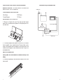
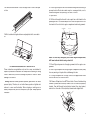
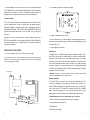
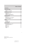
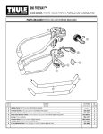
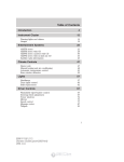
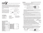
Warranty Statement
ThunderForm Loaded Enclosures purchased in the United States from an authorized MTX dealer
are guaranteed against defects in material and workmanship for a period of two years from the date
purchased by the end user, and limited to the original retail purchaser of the product.
Amplified ThunderForm Enclosures purchased in the United States from an authorized MTX dealer
are guaranteed against defects in material and workmanship for a period of one year from the date
purchased by the end user, and limited to the original retail purchaser of the product.
Product found to be defective during that period will be repaired or replaced by MTX at no charge.
This warranty is void if it is determined that unauthorized parties have attempted repairs or alterations
of any nature. Warranty does not extend to cosmetics or finish. Before presuming a defect is present
in the product, be certain that all related equipment and wiring is functioning properly. MTX disclaims
any liability for other incurred damages resulting from product defects. Any expenses incurred in the
removal and reinstallation of products are not covered by this warranty. MTX's total liability will not
exceed the purchase price of the product. If a defect is present, your authorized MTX dealer may be
able to effect repairs.
Proof of purchase is required when requesting service, so please retain your sales receipt and take
a moment to register your product online at www.mtx.com.
FORD F-150 SUPERCREW
Vehicle Specific Subwoofer Enclosure
Made in the USA
One Mitek Plaza, Winslow, IL. 61089
1-800-225-5689 www.mtx.com
21A7251
READ ALL DIRECTIONS CAREFULLY BEFORE BEGINNING
MOUNTING LOCATION: The enclosure mounts on the driver’s side
under rear seat on Ford F-150 SuperCrew.
Conventional Wiring of Aftermarket Radio
20 Amp Fuse
TOOLS REQUIRED FOR INSTALLATION:
Wire Cutters
Terminal Crimpers
5/16” Wrench
1/2" Socket
+
_
INSTALLATION: Follow the steps below
Low Level Signal
Optional EBC
(Electronic Bass Control)
STATUS
1. Remove the 2 plastic bolt covers. Press down and slide forward.
Remove the 3 seat bracket bolts, flip bottom of seat up and place enclosure under seat.
Turn On Lead
Plastic Covers
2. If externally amplified make speaker connections to the enclosure
from the amplifier; loosen terminal knobs (a 13-mm nut driver can be
used). Connect speaker wires from amplifier to enclosure, positive to red
terminal knob and negative to black terminal knob. Refer to Step 19 for
mounting directions.
AMPLIFIED THUNDERFORM
Routing Power Wire; we recommend a connection directly to the
battery.
3. Remove both passenger's side threshold trim; pull up on trim, it will
remove easily.
1
6
18. Reinstall threshold trim. Locate and align holes in vehicle with pins
on trim.
4. Route 10ga red power wire from furnished wiring harness starting at
pre-amp location. Route wire under carpet on passenger's side, over to
threshold along with factory wiring to the front of vehicle.
5. Open hood.
6. Drill a hole through the firewall. Locate a spot low on the firewall on the
passenger's side. You should always look to find a clear path. Drill a hole
from inside of the vehicle into engine compartment and insert grommet.
Drill Hole
for Grommet
Firewall
19. Bolt seat bracket legs back down and put plastic bolt covers back
on.
Battery
Note: To avoid any damage to parts inside engine compartment,
drill from inside of vehicle using a short bit.
For technical assistance call 1-800-CALL MTX.
These instructions are guidelines only and in no way are intended to
replace a professional installation. As always before screwing or drilling
check to make sure you will not damage any wires or hoses or cause
damage to the vehicle.
Warning: Batteries normally produce explosive gases which can cause
personal injury. Therefore, do not allow flames, sparks or lighted substances to come near the battery. When charging or working near a
battery, always shield your face and protect your eyes. Always provide
ventilation
5
7. Route 10ga red power wire through a grommet into the engine compartment.
8. Route 10ga red power wire through engine compartment safely away
from any moving or hot parts that could damage the wire.
9. Cut 10ga red power wire to length, connect the supplied fuse holder
from the wire kit to the end of the wire.
10. Remove 20amp fuse from MTX fuse holder. Connect furnished ring
terminal to positive side of battery. Remove 5/16" bolt from factory battery
terminal. Pass bolt through factory battery terminal, then ring terminal,
and into the other side of factory battery terminal and retighten bolt.
2
14. Plug power harness into amplifier pre-amp.
Although, MTX has made every effort to assure proper wiring colors,
MTX is not responsible for any changes made by the vehicle manufacturer which sometime occur. If wiring colors do not match then physical
verification is required.
STATUS
RIGHT
X-OVER
LEFT
EBC
GND
REM
12. In the channel on driver's and passenger's side threshold locate
the rear speaker wires. Colors are driver's side, yellow/blue (positive),
tan/yellow (negative), and passenger's side, orange/yellow (positive),
brown/purple (negative). Tap into wires with supplied RCA High Level
input wires and route under carpet to the rear seat, over to pre-amp on
enclosure.
20A
SPEAKER WIRES
GAIN
INPUT
PWR
11. Ground amplifier to chassis of vehicle; connect the terminal provided
to the 10ga black wire from furnished wiring harness. A good ground is
as important as the power connection. The ground should be as short as
possible and the contact point should be free of paint and debris.
15. Replace 20amp fuse under hood.
16. When amp turns on, LED will display red during diagnostic mode,
and then green, signaling amp is on and functioning. Amp will only turn
on when radio is on.
17. Adjust gain and crossover.
CONNECTION TO ENCLOSURE
13. Connect speaker wire RCA's to the inputs of pre-amp.
Note: Patented BTL turn on circuitry- amplifier senses DC offset provided by “high
powered” or BTL type head units. This feature turns the amplifier on automatically
if you are using high level inputs.
20 Amp Fuse
Setting Gain
Turn gain knob on Thunderform pre-amp to minimum, counter clockwise. Play a favorite tape or compact disc that contains consistent music
and bass. Turn the source unit to maximum listening level. You should
know that some source units will produce distortion or “clip” before the
unit reaches maximum volume. Reduce volume to the loudest listening
level before distortion. Turn the gain knob on the Thunderform pre-amp
clockwise until the speaker starts to distort and reduce gain to loudest
listening level before distortion.
Optional- The EBC, or Electronic Bass Control, allows a remote bass
control to be adjusted from the driver's seat.
+
_
Setting Crossover
You should set the crossover to your own personal listening taste. The
crossover is adjustable to any frequency between 50Hz (counterclockwise) to 150Hz (clockwise). As a guideline, the goal is to create the illusion of bass up front. The higher the crossover point the more “audibly
visible” your sub is going to be. Take your time and really listen to your
system, grab a soda and a few of your favorite tunes and have fun.
Optional EBC
(Electronic Bass Control)
SOLID
GAIN
GAI
X-OVER
LEFT
Tan/Yello
Tan/Y
an/Yellow (-)
STATUS
RIGHT
PWR
EBC
GND
REM
Yellow/Blue (+)
INPUT
STRIPED
Brown/Purple (-)
Orange/Yellow (+)
Orange/Y
SOLID
TROUBLESHOOTING TIPS IF AMP DOES NOT TURN ON
Check all connections at battery and that fuse is installed
Check speaker wire connections
Check ground
Check fuse on pre-amp
3
4