1
UbiSurf SM56 Software Modem
AT Command
Reference Manual
UbiSurf SM56
Notices
Information in this document is subject to change without notice.
© 2004 Motorola. All rights reserved.
Trademarks and trade names may be used in this document to refer to
either the entities claiming the marks and names or their products.
Motorola disclaims any proprietary interest in trademarks and trade
names other than its own.
Introduction
This document specifies the AT command set for Motorola UbiSurf SM56
softmodem product family. The details of the supported commands, responses, and
registers used by Motorola UbiSurf SM56 soft modem products are provided in this
reference manual.
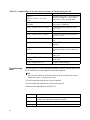
In This Document
Topic
See Page
Introduction . . . . . . . . . . . . . . . . . . . . . . . . . . . . . . . . . . . . . . . . . . . . . . . . . . . . . . . 1
AT Commands - Basics . . . . . . . . . . . . . . . . . . . . . . . . . . . . . . . . . . . . . . . . . . . . . . 2
+++ (Plus-Plus-Plus) Commands . . . . . . . . . . . . . . . . . . . . . . . . . . . . . . . . . . . . . . . 2
AT and AT& (Ampersand) . . . . . . . . . . . . . . . . . . . . . . . . . . . . . . . . . . . . . . . . . . . . 3
Table 1: AT and AT& Commands . . . . . . . . . . . . . . . . . . . . . . . . . . . . . . . . . . . 3
AT% (Percent) and AT\ (Backslash) Commands . . . . . . . . . . . . . . . . . . . . . . . . . . . 7
Table 2: AT% (Percent) and AT\ (Backslash) Commands . . . . . . . . . . . . . . . . . 7
AT* (Asterisk) Commands . . . . . . . . . . . . . . . . . . . . . . . . . . . . . . . . . . . . . . . . . . . 11
Table 3: AT* (Asterisk) Commands . . . . . . . . . . . . . . . . . . . . . . . . . . . . . . . . . 11
AT+ (Plus) Commands . . . . . . . . . . . . . . . . . . . . . . . . . . . . . . . . . . . . . . . . . . . . . . 13
Table 4: AT+ (Plus) Commands . . . . . . . . . . . . . . . . . . . . . . . . . . . . . . . . . . . . 13
ATS (S-Register) Commands . . . . . . . . . . . . . . . . . . . . . . . . . . . . . . . . . . . . . . . . . 27
Table 5: ATS (S-Register) Commands . . . . . . . . . . . . . . . . . . . . . . . . . . . . . . . 27
AT#UD Unimodem Diagnostic Command . . . . . . . . . . . . . . . . . . . . . . . . . . . . . . 29
Table 6- AT#UD Last Call Status Report Format . . . . . . . . . . . . . . . . . . . . . . 29
Table 7- Call Setup Result Codes . . . . . . . . . . . . . . . . . . . . . . . . . . . . . . . . . . 31
Table 8– Multimedia modes . . . . . . . . . . . . . . . . . . . . . . . . . . . . . . . . . . . . . . . 32
Table 9– DTE-DCE modes . . . . . . . . . . . . . . . . . . . . . . . . . . . . . . . . . . . . . . . 32
Table 10– V.34 INFO bit report (applicable only to V.34 or V.90/V.92 calls) . 32
Table 11– gstnModulationSchemeActive from 3.7.2/V.58 . . . . . . . . . . . . . . . 33
Table 12– errorControl Active from 3.5.2/V.58 . . . . . . . . . . . . . . . . . . . . . . . . 33
Table 13– compressionActive from 3.2.2/V.58 . . . . . . . . . . . . . . . . . . . . . . . . 34
Table 14– callCleared codes from 3.6.4/V.58-1994 . . . . . . . . . . . . . . . . . . . . . 34
Table 15– Completed Data Call, with some errors and rate retrain during the call
36
Event Reporting Word . . . . . . . . . . . . . . . . . . . . . . . . . . . . . . . . . . . . . . . . . . . . . . 37
1
AT Commands Basics
Attention (AT) commands are the means by which you control and monitor a
modem. Typically, the communications application automatically issues them, and
you need not know the commands and their options.
However, to custom-configure the modem for an application, or to optimize
performance, you can issue commands through the communications application
yourself. In most communications applications, there is a menu item, or option, for
entering extended or custom AT commands. See your communications application
documentation.
You can also configure the modem by issuing AT commands directly from a simple
terminal-emulation application such as ZTERM and PowerTerm.
To issue an AT command from the terminal-emulation application, you must ensure
that the modem is in command mode (in which it can detect and respond to
commands), rather than data mode (in which it is transmitting and receiving data). To
enter command mode from data mode, enter +++. You need not press the ENTER
key.
When entering AT commands, the following basic rules apply:
• AT commands can be entered in uppercase, lowercase, or mixed text
• The characters AT begin all AT commands, except A/ and +++
• The key used as the ENTER key is specified in S-Register S3
• The maximum command length is 64 characters.
You can enter more than one AT command on a line, and you can chain commands
using just one AT at the start. However, some commands must occur at the beginning
or end of the command line.
Some of the AT commands and options are product specific and may not be
applicable to the product you are using.
+++ (Plus-PlusPlus) Commands
This command, known as the escape sequence, causes the modem to stop
transmitting data (if it is doing so), and go into command mode.
Issue this command at the computer keyboard, in the communications application's
terminal window, by typing the plus sign (+) three times.
Note
Do not press the ENTER key after the +++ command. It may cancel the
command.
2
AT and AT&
(Ampersand)
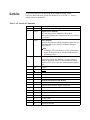
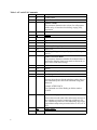
The modem responds to the following AT and AT& command options.
The letters AT (or at) must precede all commands except A/ and +++. Factorydefault options are underlined.
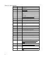
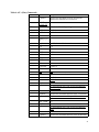
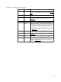
Table 1: AT and AT& Commands
Command
Option
Description
A
(none)
Answer incoming call
A/
(none)
Repeat Last Command
Re-issues the previous command to the modem.
(Do not press Return; the command executes as soon as the
/ is pressed.)
D
(none)
Dial a Number
Instructs the modem to dial the telephone number that you
enter immediately after the ATD command. Example:
ATD5554678.
Note
If multiple ATD commands are used in speakerphone
mode, the modem must be forced to blind-dial after
dial-tone detection.
E
Echo Async (Keyboard) Input to Terminal
Determines whether the characters you type at the keyboard are displayed (echoed) to the terminal-emulation
window (if it is active) or to the communications application.
E0
Disable
E1
Enable
H
Hook
H0
Go on Hook (disconnect from the telephone line; hang up)
H1
Go off Hook (connect to the telephone line)
I
Request Information From Modem
I0
“5600”
I1
Software driver Version “Apple Version ###”
I2
“OK”
I3
Software Version
I4
“Apple Internal Modem”
I5
Country Code in Hex
I6
Country Code
I7
Product Code
I8
Disconnect Reason
3
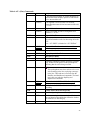
Table 1: AT and AT& Commands
Command
Option
Description
I9
Country Name
I12
Apple Product Code
L
Speaker Volume
This parameter determines the volume, for call-progress
monitor only, of sounds such as dialing, ringing, busy,
negotiation.
L0, L1
Low
L2
Medium
L3
High
M
Speaker Control
M0
Off
M1
On During Training Only
M2
Always On
M3
Off during dialing; on during call progress; off during data
transfer
O
P
Return to On-Line Mode
This parameter determines whether the modem initiates a
retrain after changing from escape mode to data mode, or
after a semi-colon in dial strings.
O0
No Retrain
O1
Retrain
O2
Initiate Rate Renegotiation
O3
Rate Renegotiation with silence
P
Pulse Dial
Instructs the modem to dial the telephone number that you
enter immediately after the ATDP command using pulse
dial mode.
Example: ATDP5554678.
This command uses Pulse Dialing to dial the number
5554678
Q
4
Result-Code Display
The modem can send result codes and connect messages to
the computer as a result of connecting or failing to connect; establishing a data rate; and establishing error-correction and data-compression protocols. Refer to: ATV; AT\V;
ATX.
Q0
Enable display
Q1
Disable display
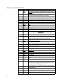
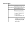
Table 1: AT and AT& Commands
Command
Option
Description
T
T
Tone Dial
This command instructs the modem to use DTMF tone
dialing.
Example: ATDT5554678.
This command uses DTMF tone Dialing to dial the number
5554678
V
Result-Code Format
Determines whether the modem sends short- or ling-form
messages to the communications application, indicating
the connection status, rate, and mode.
V0
Return Numeric Code (Short Form)
V1
Return Text (Long Form)
X
Z
Select Call-Progress Result Codes to Return
X0
No Carrier; Connect. Modem reports lack of a carrier signal; connection success/failure; modem dials without waiting for a dial tone
X1
No Carrier; Connect; Connect <rate>. Modem reports lack
of a carrier signal; connection success/failure, and the
computer data rate established
X2
No Carrier; Connect; Connect <rate>; No Dial Tone.
Modem reports lack of a carrier signal; connection success/
failure; the computer data rate established; and the lack of
a dial tone
X3
No Carrier; Connect; Connect <rate>; Busy-tone. Modem
reports lack of a carrier signal; connection success/failure;
the computer data rate established; and the presence of a
busy signal
X4
No Carrier; Connect; Connect <rate>; No Dial-tone; Busytone. Modem reports lack of a carrier signal; connection
success/failure; the computer data rate established; the lack
of a dial tone; and the presence of a busy signal
Z
Reset Modem Parameters to Default Configuration
&C
DCD Control
&C0
Always Asserted
&C1
Asserted in Data Mode Only
&D
DTR Control
Determines how modem responds to DTR signal from
DTE.
&D0
Ignore DTR
&D1
Enter Command mode when DTR transitions from
asserted to de-asserted
5
Table 1: AT and AT& Commands
Command
Option
Description
&D2
Disconnect call when DTR transitions from asserted to deasserted
&D3
Reset modem parameters to default configuration when
DTR transitions from asserted-to-de-asserted
&F
Initialize modem to default factory configuration.
&F90
Initialize modem to V.90 configuration.
&F92
Initialize modem to V.92 configuration.
&G
Guard Tone
&G0
Off
&G1
550 Hz Guard Tone
&G2
1800 Hz Guard Tone
&I
Dial TX Level
&In
Level n; n = 0 to 15. Default = 12
Note: the default value is 15 for Japan country setting.
&I99
Automatic Level
&P
Pulse Cycle
Used when the modem is instructed to pulse dial.
&P0
40/60 Make/Break Ratio
&P1
33/67 Make/Break Ratio
Note: The default value is &P1 for Japan country setting.
&P2
38/62 Make/Break Ratio
&R
CTS Control
&R0
Normal
&R1
Always On
&S
DSR Control
&S0
Always On
&S1
On When Modem Recognizes Remote
&T
Test
&T0
Terminate Test
&T1
Initiate Local Analog Loopback Test
Disconnect the telephone line from the modem line input
connector before using this command.
Set S-Register 46 = 23 (ATS46=23) before executing &T1.
&V
6
Modem Status
&V0
Short Form Report
&V1
Current or Last Connection Report
&V2
Long Form Report
AT% (Percent)
and AT\
(Backslash)
Commands
The modem responds to the following AT% and AT\ command options.
The letters AT (or at) must precede all commands except A/ and +++.
Factory-default options are underlined.
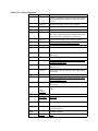
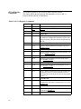
Table 2: AT% (Percent) and AT\ (Backslash) Commands
Command
Option
%B
Description
Maximum Modulation Rate
Sets the maximum rate that the modem uses when connecting in a data modulation mode for performing functions such as Internet access or file transfer
%B0
Maximum modem rate that the modem supports
%B1
300 bps
%B2
1.2 Kbps
%B3
2.4 Kbps
%B4
4.8 Kbps
%B6
9.6 Kbps
%B7
7.2 Kbps
%B8
12.0 Kbps
%B9
14.4 Kbps
%B11
16.8 Kbps
%B12
19.2 Kbps
%B13
21.6 Kbps
%B14
24.0 Kbps
%B15
26.4 Kbps
%B16
28.8 Kbps
%B17
31.2 Kbps
%B18
33.6 Kbps
%B19
32.0 Kbps
%B20
34.0 Kbps
%B21
36.0 Kbps
%B22
38.0 Kbps
%B23
40.0 Kbps
%B24
42.0 Kbps
%B25
44.0 Kbps
%B26
46.0 Kbps
%B27
48.0 Kbps
%B28
50.0 Kbps
7
Table 2: AT% (Percent) and AT\ (Backslash) Commands
Command
Option
Description
%B29
52.0 Kbps
%B30
54.0 Kbps
%B31
56.0 Kbps
%B32
58.0 Kbps
%B33
60.0 Kbps
%B34
28000 bps
%B35
29333 bps
%B36
30666 bps
%B37
33333 bps
%B38
34666 bps
%B39
37333 bps
%B40
38666 bps
%B41
41333 bps
%B42
42666 bps
%B43
45333 bps
%B44
46666 bps
%B45
49333 bps
%B46
50666 bps
%B47
53333 bps
%B48
54666 bps
%C
Data Compression (DC) Mode
Determines whether the modem implements methods of
increasing the effective data rate by reducing the number
of bits used to represent data
%C0
Disable Compression
%C1
Enable Compression
%D
Disconnect Buffer Delay
Controls the delay after detection of a disconnect request
before the modem disconnects from the telephone line
%D0
Disable Delay
%Dn
Delay for n Seconds (n = 1 to 255)
%L
8
Minimum Modulation Rate
Sets the minimum rate that the modem uses when connecting in a data modulation mode.
%L0
Minimum modem rate that the modem supports(300 bps)
%L1
300 bps
%L2
1.2 Kbps
Table 2: AT% (Percent) and AT\ (Backslash) Commands
Command
Option
Description
%L3
2.4 Kbps
%L4
4.8 Kbps
%L7
7.2 Kbps
%L6
9.6 Kbps
%L8
12.0 Kbps
%L9
14.4 Kbps
%L11
16.8 Kbps
%L12
19.2 Kbps
%L13
21.6 Kbps
%L14
24.0 Kbps
%L15
26.4 Kbps
%L16
28.8 Kbps
%L17
31.2 Kbps
%L18
33.6 Kbps
%L19
32.0 Kbps
%L20
34.0 Kbps
%L21
36.0 Kbps
%L22
38.0 Kbps
%L23
40.0 Kbps
%L24
42.0 Kbps
%L25
44.0 Kbps
%L26
46.0 Kbps
%L27
48.0 Kbps
%L28
50.0 Kbps
%L29
52.0 Kbps
%L30
54.0 Kbps
%L31
56.0 Kbps
%L32
58.0 Kbps
%L33
60.0 Kbps
%L34
28000 bps
%L35
29333 bps
%L36
30666 bps
%L37
33333 bps
%L38
34666 bps
%L39
37333 bps
9
Table 2: AT% (Percent) and AT\ (Backslash) Commands
Command
Option
Description
%L40
38666 bps
%L41
41333 bps
%L42
42666 bps
%L43
45333 bps
%L44
46666 bps
%L45
49333 bps
%L46
50666 bps
%L47
53333 bps
%L48
54666 bps
\K
Break Handling Method
\K1
Destructive Expedited
\K3
Non-destructive Expedited
\K5
Non-destructive Non-expedited
\N
Error-Correction (EC) Mode
\N0
Normal
\N1
Direct
\N4
LAP-M Only
\N6
Reliable
\N7
Auto-Reliable
\Q
DTE Flow Control
\Q0
Disable
\Q1
XON/XOFF (software flow control)
\Q3
RTS/CTS (hardware flow control)
\T
Disconnect on DTE Inactivity
\T0
Disable
\Tn
Disconnect after n minutes of inactivity by the computer;
n = 0 to 255
\V
10
Connect Message Format
Determines which messages the modem generates at connection time
\V0
Display DTE Rate
\V1
DTE with EC/DC message
\V2
Display DCE Rate
\V3
DCE with EC/DC Message
\V4
DCE with Modulation & EC/DC Message
AT* (Asterisk)
Commands
The modem responds to the following AT* command options.
The letters AT (or at) must precede all commands except A/ and +++.
Factory-default options are underlined
Table 3: AT* (Asterisk) Commands
Command
Option
*DD
Description
Dial Wait
Specifies the time interval to wait when the modem
encounters a W or w while processing a dial string
*DD0
2 Seconds
*DD1
3 Seconds
*DD2
4 Seconds
Note: the default value is *DD2 for Japan country setting.
*DD3
5 Seconds
*DD4
12 Seconds
*DD5
15 Seconds
*DD6
20 Seconds
*DD7
30 Seconds
*DD8
40 Seconds
*LS
Low-Speed Operation Protocol
Lets you select a communications protocol to communicate with very low-speed or older modems.
*LS0
Bell 103
*LS1
ITU-T V.21 (international standard)
*LS2
Bell 103 or ITU-T V.21 (Auto determination)
*MM
Modulation Mode
*MM0
V.34 Auto Modulation
*MM1
V.21
*MM2
Bell 103
*MM4
V.22/Bell 212
*MM5
V.22bis
*MM6
V.23
*MM10
V.32 Only
*MM11
V.32 bis
*MM12
V.34 Only
*MM13
K56flex™ Only
11
Table 3: AT* (Asterisk) Commands
Command
12
Option
Description
*MM14
K56flex™ Auto-modulation
*MM15
V.90 Only
*MM16
V.90 Auto
*MM17
V.92 Only
*MM18
V.92 Auto
AT+ (Plus)
Commands
The modem responds to the following AT+ command options.The letters AT
(or at) must precede all commands except A/ and +++.
Factory-default options are underlined.
AT commands that begin with:
+D control data compression
+F control fax application operation
These commands are primarily used by software applications.
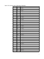
Table 4: AT+ (Plus) Commands
Command
Option
+A8E
Description
V.8 Configuration
+A8=a,b,c,d
a options:
Specifies V.8 origination negotiation options
0
Disable
1
Enable computer-controlled V.8 origination negotiation
6
Enable computer-controlled V.8 origination negotiation with +A8x indications
b options:
Specifies V.8 answer negotiation options
0
Disable
1
Enable computer-controlled V.8 answer negotiation
5
Enable computer-controlled V.8 answer negotiation
with +A8x indications
c options:
Specifies the V.8 CI Signal Call Function Octet
options
00h - FFh,
default=00h
d options:
Specifies V.8 control options
0
Disabled
1
Enabled, modem control
2
Enabled, computer control
+A8T
V.8bis Signal and Message Control
+A8T=a,b,c,
d,e,f
a options:
Specifies V.8bis Signal to Transmit
0
None
1
Initiating MRe
13
Table 4: AT+ (Plus) Commands
Command
Option
Description
2
Initiating MRd
3
Initiating Cre, low power
4
Initiating Cre, high power
5
Initiating Crd
6
Initiating Esi
7
Responding MRd, low power
8
Responding MRd, high power
9
Responding CRd
10
Responding ESr
b options:
Specifies V.8bis Transmit Message 1
hexadecimal octet coded string
c options:
Specifies V.8bis Transmit Message 2
hexadecimal octet coded string
d options:
Specifies V.8bis signal detection
0
Enable detection of initiating V.8bis signal
1
Enable detection of responding V.8bis signal
2
Enable detection of both V.8bis signals
e options:
Specifies V.8bis message detection
0
Disable detection
1
Enable detection
f options:
Specifies the V.8bis message delay
0
No delay between transmitting signal and messages
1
1.5 second delay between transmitting signal and
any message
+DR
Data Compression (DC) Reporting
+DR=0
Disabled
+DR=1
Enabled
+DS
Data Compression Control
+DS=p,q,r,s
14
p options:
Specifies compression on/off direction
0
No compression
1
Tx direction only
2
Rx direction only
3
Both directions; accept any direction
q options:
Specifies negotiation
Table 4: AT+ (Plus) Commands
Command
Option
Description
0
Do not disconnect if data compression is not negotiated per Direction option
1
Disconnect if data compression is not negotiated per
Direction option
r options:
Specifies maximum dictionary size
512 - 65535
Default = 2048
s options:
Specifies maximum string size
6 - 250
Default = 32
+EB
Break Handling Control
+EB=p,q r
p options:
Specifies break selection
0
Ignore break
1
Non-expedited, non-destructive
2
Expedited, non-destructive
3
Expedited, destructive
q options:
Specifies break length control
0
Transmission of V.42 L-SIGNAL does not indicate
break length
1
Transmission of V.42 L-SIGNAL indicates break
length
r options:
Specifies the default break-length
0
Break is not transmitted to the computer
1- 254,
default=100
Break length, in 0.01-second increments
+ER
Error-Control Reporting
Specifies the modem’s error-control reporting activity.
0
Disabled
1
Enabled: modem issues one of the following messages to the computer, before it issues a connect
message. The message specifies the Error Correction
protocol negotiated: +ER:NONE +ER:LAPM
+ER:ALT
+ES
Error-Correction (EC) Control
+ES=p,q r
p options:
Specifies the originate-modem’s Request Error Correction mode
0
Direct mode
15
Table 4: AT+ (Plus) Commands
Command
Option
Description
1
Normal mode
2
LAP-M Only
3
LAP-M or MNP
4
MNP Only
6
Initiate Sync Access mode when connection is established
q options:
Specifies the answer-modem’s Fallback Error Correction mode
0
EC optional, fallback to Normal mode
1
EC optional, fallback to Direct mode
2
EC required (LAP-M or MNP)
3
EC required (LAP-M only)
4
EC required (MNP only)
r options:
Specifies the originate-modem’s Fallback Error Correction mode
0
Direct mode
1
Normal mode
2
EC optional, fallback to Normal mode
3
EC optional, fallback to Direct mode
4
EC required (LAP-M or MNP)
5
EC required (LAP-M only)
6
EC required (MNP only)
8
Initiate synchronous access mode when connected
+ESA
Synchronous Access Mode Configuration
+ESA=a,b,c,
d,e,f
16
a options:
Specifies the Idle in Transparent sub-mode
0
Computer transmits 8 bit SYN sequence on idle.
Computer does not hunt for synchronization
sequence
b options:
Specifies the Idle in Framed sub-mode
0
Computer transmits HDLC flags on idle
c options:
Specifies under-run and over-run in Framed submode
0
Computer transmits Abort on an under-run within a
frame
Table 4: AT+ (Plus) Commands
Command
Option
Description
1
Computer transmits a Flag on an under-run within a
frame, and notifies the modem of any under-run or
over-run
d options
Specifies half-duplex control. Not available.
e options
Specifies the Cyclic Response Code (CRC) type
0
Disabled. No CRC generation or checking.
1
In Framed sub-mode, the computer generates 16-bit
CRC in the Transmit direction and the modem generates 16-bit CRC on the Receive direction.
f options:
Specifies Non-Return to Zero (NRZI) options
0
NRZI encoding and decoding are disabled.
+ETBM
Disconnect Buffer Delay Control
+ETBM=p,q
r
p options:
Specifies the disconnect buffer delay with pending
transmit data
0
Discard buffered data and disconnect
1
Attempt to transmit until all data is delivered, then
disconnect. Ignore timer.
2
Attempt to transmit until all data is delivered or
timer expires.
q options:
Specifies the disconnect buffer delay with pending
receive data
0
Discard buffered data and disconnect
1
Attempt to transmit until all data is delivered, then
disconnect. Ignore timer.
2
Attempt to transmit until all data is delivered or
timer expires.
r options:
1-255,
default=0
Disconnect buffer delay timer, in 1-second increments
+FCLASS
Fax/Data Mode
+FCLASS=
0
Data Mode
+FCLASS=
1
Fax Class 1
+FCLASS=
8
Voice Mode (Not available in Data/Fax and Data/
Fax/TAM modems.)
+FLO
Fax Flow Control
+FLO=0
None
17
Table 4: AT+ (Plus) Commands
Command
Option
Description
+FLO=1
XON/XOFF
+FLO=2
RTS/CTS
+FMI?
Report Manufacturer ID
+FMM?
Report Modem ID
+FMR?
Report Revision Level
+FRH
Receive High-Level Data Link Control (HDLC)
Mode Sets mode and transmit/receive rate for
faxes
+FRH=3
V.21 at 300 bps
+FRH=24
V.27ter at 2.4 Kbps
+FRH=48
V.27ter at 4.8 Kbps
+FRH=72
V.27ter at 7.2 Kbps
+FRH=73
V.27ter at 7.2 Kbps with long train time
+FRH=74
V.27ter at 7.2 Kbps with short train time
+FRH=96
V.29 at 9.6 Kbps
+FRH=97
V.17 at 9.6 Kbps with long train time
+FRH=98
V.17 at 9.6 Kbps with short train time
+FRH=121
V.17 at 12.0 Kbps with long train time
+FRH=122
V.17 at 12.0 Kbps with short train time
+FRH=145
V.17 at 14.4 Kbps with long train time
+FRH=146
V.17 at 14.4 Kbps with short train time
+FRM
Receive Mode Sets the modulation mode for
receiving faxes
+FRMm
+FRS
Wait for Silence
+FRSn
+FTH
+FTM
Use mode mode; see options for +FRH, above.
Transmit Mode Sets the modulation mode for transmitting faxes
+FTMmode
+FTS
Use mode mode; see options for +FRH, above.
Pause Transmission
+FTSn
+GCAP
Pause transmission for (n*10) ms; n=0 to 255
Report Capabilities
+GCAP
18
Wait (n*10) ms; n=0 to 255
Transmit High-Level Data Link Control (HDLC)
Mode
+FTHmode
+GCI
Use mode m; see mode options for +FRH, above.
Display modem capabilities
Country of Installation
Table 4: AT+ (Plus) Commands
Command
Option
Description
+GCI=a
Set country in which modem is installed
00
Japan
04
Germany
07
Argentina
09
Australia
0A
Austria
0F
Belgium
16
Brazil
1B
Bulgaria
20
Canada
25
Chile
26
China
27
Columbia
2E
Czech Republic
2D
Cyprus
31
Denmark
3C
Finland
3D
France
42
Germany
50
Hong Kong
57
Ireland
58
Israel
59
Italy
5E
Jordan
61
Korea
68
Liechtenstein
6C
Malaysia
70
Malta
7B
Netherlands
82
Norway
8B
Portugal
8C
Puerto Rico
9C
Singapore
9F
South Africa
A0
Spain
19
Table 4: AT+ (Plus) Commands
Command
Option
Description
A5
Sweden
A6
Switzerland
A9
Thailand
AE
Turkey
B4
United Kingdom
B5
USA
BB
Venezuela
BC
Vietnam
+GMI
Request Manufacturer ID
+GMI?
+GMM
Display modem-manufacturer information
Request Model ID
+GMM?
+GMR
Display modem-model information
Request Software Revision Number
+GMR?
+IFC
Display modem-software revision number
Flow Control
+IFC=p,q
p options:
Specifies the computer’s flow control method for
data passing to the modem (downstream)
0
None
1
XON/XOFF flow control, no pass-through
2
RTS flow control
3
XON/XOFF flow control, with pass-through
q options:
Specifies the modem’s flow control method for data
passing from the modem (upstream)
0
None
1
XON/XOFF flow control, no pass-through
2
CTS flow control
+ILRR
Computer’s Local Rate Reporting
+ILRR=0
Disabled
+ILRR=1
Enabled
+ITF
Transmit Flow Control Thresholds (V.80)
+ITF=a,b
a options:
0-2047
default=255
20
Specifies the threshold, in octets, at which the
modem turns transmit flow-control off
Table 4: AT+ (Plus) Commands
Command
Option
Description
b options:
Specifies the threshold, in octets, at which the
modem turns transmit flow-control on
0-2047
default=255
+MR
Modulation Mode Reporting
+MR=0
Disabled
+MR=1
Enabled
+MS
Modulation Control
+MS=p,q,r,s,
t,u
p options:
Specifies the modulation mode
V21
V.21
V22
V.22
V22B
V.22bis
V23C
V.23c
V32
V.32
V32B
V.32bis
V34
V.34
K56FLEX
K56flex™
V90
V.90
V92
V.92
q options:
Specifies the Automode option
0
Disabled
1
Enabled
r options:
Specifies the minimum data rate in the Tx direction
0
Use the minimum rate of the specified modulation
mode (300 bps)
300 - 33600
bps
s options:
Specifies the maximum data rate in the Tx direction
0
Use the maximum rate of the specified modulation
mode
300 - 33600
bps
t options:
Specifies the minimum data rate in the Rx direction
0
Use the minimum rate of the specified modulation
mode
300 - 60000
bps
u options:
Specifies the maximum data rate in the Rx direction
21
Table 4: AT+ (Plus) Commands
Command
Option
Description
0
Use the maximum rate of the specified modulation
mode
300 - 60000
bps
+PCW
Call Waiting Enable
This option controls the action to execute upon
detecting a call waiting signal.
+PCW=0
Toggle the RI signal and collect Caller Identification
if enabled
+PCW=1
Hang up the modem
+PCW=2
Ignore the call waiting ID signal
+PCW=3
Disable call waiting detection.
+PCW=?
Display Call Waiting Status
+PMH
Modem on Hold Enable
This command controls the enabling of modem on
hold execution.
+PMH=0
Enable modem on hold
+PMH=1
Disable modem on hold negotiation.
+PMH=?
Display Modem on Hold Status
+PMHT
Modem on Hold Timer
This command controls whether to grant or deny a
remote modem on hold request. If the request is
granted, it also controls the amount of time allowed
for the timeout.
22
+PMH=0
Deny remote requests
+PMH=1
10 seconds
+PMH=2
20 seconds
+PMH=3
30 seconds
+PMH=4
40 seconds
+PMH=5
1 minute
+PMH=6
2 minutes
+PMH=7
3 minutes
+PMH=8
4 minutes
+PMH=9
6 minutes
+PMH=10
8 minutes
+PMH=11
12 minutes
+PMH=12
16 minutes
+PMH=13
Indefinite
Table 4: AT+ (Plus) Commands
Command
Option
Description
+PMH=?
Display Modem on Hold Timer Status
+PMHR
Initiate Modem on Hold
This command requests the modem to initiate the
modem on hold procedure. If MH is disabled, or if
the remote side rejects the request, an ERROR message is returned. Otherwise, the message
“+PMHR:<t>” is returned, where <t> is the allowed
timeout.
+PMF
Modem Hook Flash
This command cause the modem to perform a flash
hook operation.
+PQC
Phase 1 and Phase 2 control
This command controls the use of full or shortened
Phase 1 and Phase2 startup procedures.
+PQC=0
Enable Short Phase 1 and Short Phase 2
+PQC=1
Enable Short Phase 1 and Full Phase 2
+PQC=2
Enable Full Phase 1 and Short Phase 2
+PQC=3
Enable Full Phase 1 and Full Phase 2
+PQC=?
Display Quick Connect Status
+VCID
Caller ID Control
This option takes effect only where the function is
supported. Data/Fax modems do not support this
option.
+VCID=0
Disable
+VCID=1
Enable
+VCID=?
Display Caller ID Status (returns 0 or 1)
+VDR
Distinctive Ring Control and Report
This option takes effect only where the function is
supported. Data/Fax modems do not support this
option
+VDR=m,n
Note
If Distinctive Ring is enabled, the first ring
reported by the modem may be incorrect.
m options:
Specifies control
0
Disable
1
Enable
n options:
Specifies reporting
0
Produce DROFF/DRON report, no RING
23
Table 4: AT+ (Plus) Commands
Command
Option
Description
1-255
Produce DROFF/DRON, followed by RING after
delay of n/10 seconds
+VEM
Event Reporting and Masking Control
Data/Fax/Speakerphone modem only
Bit-mapped event control mask. See Event Reporting Word.
+VGR
Receive Gain
Data/Fax/Speakerphone modem only
0
Automatic Gain Control
1-255
Relative range, where 128 indicates a nominal value.
+VGT
Transmit Volume
Data/Fax/Speakerphone modem only
1-255
+VIP
"Relative range, where 128 indicates a nominal
value.
Initialize Voice Parameters
Data/Fax/Speakerphone modem only
Set speakerphone parameters to factory-default
options.
+VLS
Select Analog Source and Destination
Data/Fax/Speakerphone modem only
0
DCE (modem) on-hook
1
DCE off-hook, DCE connected to telco
8
DCE on-hook, DCE connected to speaker
9
speakerphone with mute enabled
11
DCE on-hook, DCE connected to microphone
13
DCE off-hook, DCE connected to telco, speaker, and
microphone (speakerphone)
+VNH
Automatic Hangup Control
Data/Fax/Speakerphone modem only
+VNH=0
Retain automatic hang-ups
+VNH=1
Disable DCE-initiated automatic hang-ups
+VNH=2
Disable all Automatic hang-ups
+VPR
Voice DTE-DCE Rate
Data/Fax/Speakerphone modem only
+VPR=0
+VRA
Autobaud
Ringback Gone Timer
Data/Fax/Speakerphone modem only
24
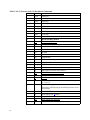
Table 4: AT+ (Plus) Commands
Command
Option
Description
If, after detecting ringback, no further ringbacks are
detected after n/10 seconds, operate as if the remote
device answered the call.
+VRA=n
If no ringback is received, after n/10 seconds,
assume that the remote device has answered the call;
n = 0-255
Ringback Never Occurred
+VRN=n
+VRID
After n/10 seconds, operate as if ringback never
occurred; n = 0-255
Repeat Caller ID
This command instructs the modem to send all available call information on the last incoming call to the
DTE.
Note: “AT+VRID” is identical to “AT+VRID=0”
+VRID or
+VRID=0
Display Caller ID information in formatted form
+VRID=1
Display Caller ID information in unformatted form
+VRID=?
Display Repeat Caller ID Status
+VRX
Voice Receive Mode
Data/Fax/Speakerphone modem only
Determines whether the modem generates a periodic
beep, audible to both parties on the speakerphone,
indicating that the call is being recorded.
Note
The speakerphone state does not have to be reset
after recording to the line or playing a message
to the line. The baud rate is not set before the
StartPlay and StartRecord commands. The baud
rate is not reset after the StopPlay and
StopRecord commands.
+VRX or
+VRX=0
Produce Periodic DCE Tone While Recording
+VRX=1
Disable Periodic DCE Tone Production During
Recording
+VSD
Remote Silence-Detection Properties
Data/Fax/Speakerphone modem only
+VSD=m,n
Used in answering-machine mode. Specifies the volume and duration thresholds that determine whether
the remote device has hung up.
m options:
Specifies the silence-detection level
25
Table 4: AT+ (Plus) Commands
Command
Option
Description
0
Use current +VSM value; or, if current +VSM value
is 0, use 128.
127
Low Threshold (most sensitive)
128
Medium Threshold
129
High Threshold (least sensitive)
n options:
Specifies the silence-detection duration
0
Disable
1-255
Detect n/10 seconds silence; n = 0-255
50
Default = 5 seconds
+VSM
Speech Compression Properties
Data/Fax/Speakerphone modem only
+VSM=m,n, Specifies the speakerphone compression parameters
p,q
m options:
Specifies the compression method
128
PCM
129
ADPCM
n options:
Specifies the sampling rate to determine whether to
compress
8000
8000 Hz
p options:
Parameter p specifies compression and expansion of
periods of silence. These parameters are not implemented in Release 1.0. You may leave them blank or
enter the value 0.
0
Disable
q options:
Parameter q specifies compression and expansion of
periods of silence. These parameters are not implemented in Release 1.0. You may leave them blank or
enter the value 0.
0
Disable
+VTD
Dual Tone Multi-Frequency (DTMF) Tone Duration
Data/Fax/Speakerphone modem only
+VTDn
+VTS
Generates tone for n/100 seconds; n = 0-255.
Default=100.
DTMF Tone Generation Properties
Data/Fax/Speakerphone modem only
+VTS accepts multiple options, separated by commas, of any of the following types. Use square or
curly brackets as shown.
26
Table 4: AT+ (Plus) Commands
Command
+VTX
Option
Description
D
Generate default DTMF Tone, default duration.
{t,n}
t specifies a DTMF tone; t = 0-9
n specifies tone duration n/100 seconds; n = 1-500
{f,g,n}
f and g specify a tone pair, f Hz and g Hz; in the
range n
Specifies tone-pair duration n/100 seconds; n = 1500
Example:
AT+VTS=4,{},[1000,1300,50],8,{*,5},[,,100],5
This example specifies the following sequence:
1. Play DTMF 4 for the duration stored in +VTD
2. Play silence for the duration stored in +VTD
3. Play tone pair at 1000 Hz and 1300 Hz for 500 ms
4. Play DTMF 8 for a duration stored in +VTD
5. Play DTMF * for 50 ms
6. Play silence for 1 second
7. Play DTMF 5 for the duration stored in +VTD
Enter Voice-Transmission Mode
Data/Fax/Speakerphone modem only
Note
The speakerphone state does not have to be reset
after recording to the line or playing a message
to the line. The baud rate is not set before the
StartPlay and StartRecord commands. The baud
rate is not reset after the StopPlay and
StopRecord commands.
27
ATS (S-Register)
Commands
The modem responds to the following ATS command options.
The letters AT (or at) must precede all commands except A/ and +++.
Factory-default options are underlined.
Table 5: ATS (S-Register) Commands
S-Register
Option
S0
Auto-Answer on Ring Number
S0=0
Disable
S0=n
Answer on Ring n; n=0 to 255
S1
Ring Count
S1=n
S2
S3
Specifies ASCII character for Escape; n=0 to 255.
Default = 43 (+)
Select Carriage-Return Character
S3=n
S4
Specifies ASCII character for Carriage-Return; n=0
to 127. Default = 13 (CR)
Select Line-Feed Character
S4=n
S5
Specifies ASCII character for Line-Feed; n=0 to
127. Default = 10 (LF)
Select Backspace Character
S5=n
S6
Specifies ASCII Character for Backspace; n=0 to
127. Default = 8 (BS)
Blind Dial
S6=n
S7
Before dialing, the modem goes off-hook and waits
n seconds; n=0 to 255. Note: When the ATX2 or
ATX4 option is in effect, the S6 value is disregarded.
Default = 2
Call Time-out
S7=n
S8
Number of seconds in which connection must be
established or call will be disconnected; n=1 to 255.
Default = 60
Pause Delay
S8=n
28
Counts the number of rings in an incoming call. If
the modem is configured to auto-answer (S0 set to a
non-zero option), when S1=S0, the modem answers
the call.
Select Escape Character
S2=n
S10
Description
Pause for n seconds; n=0 to 255; for dial modifier in
a dial string. Default = 2
DCD Loss Disconnect
Table 5: ATS (S-Register) Commands
S-Register
Option
Description
S10=n
Disconnect after n seconds; n=0 to 255 in 0.1 second
increments; after DCD signal is de-asserted. Default
= 14
S11
Tone Length
S11=n
S12
Specifies duration, in 0.001 second increments, of
DTMF tone when it is generated; n=60 to 255.
Default =80
Escape Code Guard Time
S12=n
S18
Specifies the interval, in 0.02-second increments,
that must be present on either side of the escape code
(+++) for the modem to recognize the escape command and enter command mode. If S12=0, the speed
at which you enter the escape sequence is not a factor. Default = 50
Test Timer
S18=n
S92
Specifies test execution duration; n=0 to 255.
Default = 0
Modem-on-Hold Messaging Monitoring
S92=n
Specifies the enable(n=1) or disable(n=0) of the
Modem-on-Hold UbiSurf SM56 tray applet helper
messaging. Default = 1
29
AT#UD Unimodem
Diagnostic
Command
The Unimodem Diagnostic Command Specification is provided by Microsoft
to enable modems to exhibit consistent behavior during data session diagnostics. The latest specification revision of this command can be found on the
Microsoft Web site.
Command Syntax:
AT#UD
#UD is an action command. It does not take parameters.
Although this command is intended for use after call termination, codes are
defined so that a modem can respond before the call is placed, and during a
call for live monitoring purposes.
Command Response:
In response to this command, the modem reports information about the
modem. Each information text line is formatted as follows, including one or
more key=value pairs:
DIAG <token key = value [[key = value] [key = value]] …>
Where, token is a unique 32-bit hex number 2A4D3263
key is a hex number, described in column 1 of Table 1.
value is a string defined by column 2 in Table 1.
Note
Unless otherwise noted, all values are hexadecimal numbers.
Table 6- AT#UD Last Call Status Report Format
Key
Value
Definition
0
2 digits
Diagnostic Command Specification revision number
1
See Table 7
Call Setup Result code
2
See Table 8
Multi-media mode
3
See Table 9
DTE-DCE interface mode
4
String
V.8 CM octet string, same format as V.25ter Annex
A, in quotes
5
String
V.8 JM octet string, same format as V.25ter Annex
A, in quotes
6-F
30
Reserved for call negotiation reports
10
0-2F
Received signal power level, in –dBm (0-43)
11
0-1F
Transmit signal power level, in –dBm (e.g. 0-17)
12
0-64
Estimated noise level, in –dBm (e.g. 10-90)
Table 6- AT#UD Last Call Status Report Format
Key
Value
Definition
13
0-FF
Normalized Mean Squared error, 100 (0x64) = minimum inter-symbol distance
14
0-3F
Near echo loss, in units of dB
15
0-3F
Far echo loss, in units of dB
16
0-3F
Far echo delay, in units of ms
17
0-FFF
Round Trip delay, in units of ms
18
See Table 10 V.34 INFO bit map
19-1F
Reserved for modulation setup and training reports
20
See Table 11
Transmit Carrier Negotiation Result
21
See Table 11
Receive Carrier Negotiation Result
22
0-1F40
Transmit Carrier symbol rate (0-8000) in symbol/s
23
0-1F40
Receive Carrier symbol rate (0-8000) in symbol/s
24
0-FA0
Transmit Carrier frequency (0-4000) in Hz
25
0-FA0
Receive Carrier frequency (0-4000) in Hz
26
0-FA00
Initial transmit carrier data rate (0-64000) in bit/s
27
0-FA00
Initial receive carrier data rate (0-64000) in bit/s
28-2F
Reserved
30
0-FF
Temporary carrier loss event count
31
0-FF
Carrier Rate re-negotiation event count
32
0-FF
Carrier Retrains requested
33
0-FF
Carrier Retrain requests granted
34
0-FA00
Final transmit carrier data rate in bit/s
35
0-FA00
Final receive carrier data rate in bit/s
36-3F
Reserved
40
See Table 12 Protocol Negotiation Result
41
0-400
Error Control frame size in bytes
42
0-FF
Error control link timeouts in transmission
43
0-FF
Error control link NAKs received
44
See Table 13 Compression Negotiation Result
45
0-800
46-4F
Compression dictionary size in bytes
Reserved
50
0-2
Transmit flow control: 0 = off; 1 = DC1/DC3; 2 =
V.24 ckt 106/133
51
0-2
Receive flow control: 0 = off; 1 = DC1/DC3; 2 =
V.24 ckt 106/133
52
0-FFFFFFFF Transmit characters sent from DTE
31
Table 6- AT#UD Last Call Status Report Format
Key
Value
53
0-FFFFFFFF Received characters sent to DTE
54
0-FFFF
Transmit characters lost (data overrun errors from
DTE)
55
0-FFFF
Received characters lost (data overrun errors to
DTE)
56
0-FFFFFFFF Transmit I- Frame count, if error control protocol
running
57
0-FFFFFFFF Received I-Frame count, if error control protocol
running
58
0-FFFF
Transmit I-Frame error count, if error control protocol running
59
0-FFFF
Received I- Frame error count, if error control protocol running
5A-5F
60
Definition
Reserved
See Table 14 Termination Cause
62-7F
Reserved for future versions of this specification
80-FF
Reserved for manufacturer proprietary keys
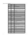
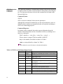
Table 7- Call Setup Result Codes
32
Code
Definition
0
No previous call (modem log has been cleared since any previous
calls)
1
No dial tone detected
2
Reorder signal detected, network busy
3
Busy signal detected
4
No recognized signal detected (e.g. no signal, or nothing recognizable)
5
Voice detected * if this is a voice modem (e.g. V.253) operating in
voice mode (e.g. +FCLASS=8.0)
6
Text telephone signal detected (see V.18)
7
Data Answering signal detected (e.g. V.25 ANS, V.8 ANSam)
8
Data Calling signal detected (e.g. V.25 CT, V.8 CI)
9
Fax Answering signal detected (e.g. T.30 CED, DIS)
A
Fax Calling signal detected (e.g. T.30 CNG)
B
V.8bis signal detected
C-F
Reserved
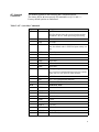
Table 8– Multimedia modes
Code
Definition
0
Data Only
1
FAX Only
2
Voice Only * if voice mode supported (e.g. V.253, IS-101)
3
VoiceView™
4
ASVD, V.61
5
ASVD, “V.34Q”
6
DSVD, Multi-Tech
7
DSVD, 1.2
8
DSVD, V.70
9
Video-telephony, H.324
A
Other V.80 call
B-F
Reserved
Table 9– DTE-DCE modes
Code
Definition
0
Async data
1
V.80 transparent synchronous mode
2
V.80 framed synchronous mode
3-F
Reserved
Table 10– V.34 INFO bit report (applicable only to V.34 or V.90/V.92 calls)
Bits
Source bits
Definition
31-30
INFO0 bit 20; 0
20-29
INFOc bits 79-88
16-19
INFOc bits 26-29 Pre-emphasis field, selected by the symbol
or 35-38 or 44-47 rate chosen
or 53-56- or 62-65
or 71-74
15-Dec
INFOa bits 26-29
11-Oct
MP bit 50; 0
0-9
INFOa bits 40-49
33
Table 11– gstnModulationSchemeActive from 3.7.2/V.58
Value
Description
0
V.17 (G3 Fax call)
1
V.21
2
V.22
3
V.22bis
4
V.23 Constant Carrier (1200/75)
5
V.23 Switched Carrier (half duplex)
6
V.26bis
7
V.26ter
8
V.27ter (G3 Fax call)
9
V.29 HD (G3 Fax call)
A
V.32 (difficult to distinguish from V.32bis)
B
V.32bis
C
V.34
D
V.34 HD (G3 Fax call)
E
V.90 Issue 1 (asymmetric)
F
V.90 Issue 2 (symmetric)
E-7F
Reserved (V.58)
80
X2™
81
K56FLEX™
82
V.FC
83
V.32terbo
84
Bell 212A (if modem supports B212A)
85
Bell 103 (if modem supports B103)
80-FF
Reserved for mfgs
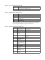
Table 12– errorControl Active from 3.5.2/V.58
Value
34
Description
0
Disable/none
1
V.42 LAPM
2
V.42 Alterative protocol (MNP™)
3-7F
Reserved (V.58)
80
MNP10™
81
ECP™ Enhanced Cellular Protocol
Table 12– errorControl Active from 3.5.2/V.58
Value
Description
82
ETC™ Enhanced Throughput Cellular
82-FF
Reserved for mfgs
Table 13– compressionActive from 3.2.2/V.58
Value
Description
0
None
1
V.42bis
2-7F
Reserved (V.58)
80
MNP5™
81-FF
Reserved for mfgs
Indicates that the DCE has gone on hook and that the previously existing
network connection has been cleared. These values are hex.
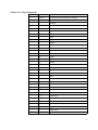
Table 14– callCleared codes from 3.6.4/V.58-1994
Value
Description
Notes
0
CauseUnidentified
Call setup issues
1
No Previous call
Not in V.58
2
Call is still in progress
Not in V.58
3
Call Waiting signal
detected
Not in V.58, only if modem can detect it
4
Delayed
Same as value 2A, CallAttemptsLimitExceeded
A
NMSinitiatedDialCall
-- Network Management System
B
NMSinitiatedLeasedLineRestoral
C
NMSinitiatedRedial
D
NMSinitiatedDialDisconnect
14
PowerLoss
15
EquipmentFailure
16
FrontPanelDisconnectRequested
17
FrontPanelLeasedLineRestoral
18
AutomaticLeasedLineRestoral
DCE
If there is a front panel with this control
35
Table 14– callCleared codes from 3.6.4/V.58-1994
Value
36
Description
Notes
19
InactivityTimerExpired
1E
cct116RestoralRequest
1F
cct108isOffInhibitsDia
l
20
cct108turnedOff
This is hangup with &D2
28
NoNumberProvided
Prohibited by some national regulations
29
BlacklistedNumber
2A
CallAttemptsLimitExceeded
Same as “Delayed”, see ETS 300 001
2B
ExtensionPhoneOffHook
If extension detection supported
2C
CallSetupFailTimerEx- e.g. S7 timeout
pired
2D
IncomingCallDetected
2E
LoopCurrentInterrupted
2F
NoDialTone
30
VoiceDetected
31
ReorderTone
32
SitTone
33
EngagedTone
34
LongSpaceDisconnect
And if modem program to abort on long
space
3C
CarrierLost
Signal Converter
3D
TrainingFailed
3E
NoModulationinCommon
3F
RetrainFailed
40
RetrainAttemptCountExceeded
41
GstnCleardownReceived
42
FaxDetected
46
InTestMode
47
IntrusiveSelfTestInitiated
50
AnyKeyAbort
DTE Interface
If incoming call while sending dial command.
Test
Call Control
Table 14– callCleared codes from 3.6.4/V.58-1994
Value
Description
Notes
51
DteHangupCommand
If ATH was used to terminate the previous
call.
52
DteResetCommand
If ATZ was used to terminate the previous
call.
5A
FrameReject
Error Control
5B
NoErrorControlEstablished
Error control was required
5C
ProtocolViolation
5D
n400exceeded
5E
NegotiationFailed
5F
DisconnectFrameReceived
60
SabmeFrameReceived
64
LossOfSynchronization
Data Compression
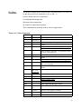
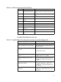
Example Modem Response and Usage
Table 15 - Completed Data Call, with some errors and rate retrain during the call
Modem response line
Description
DIAG <2A4D3263 0=10
This is version 1.0
DIAG <2A4D3263 1=06 2=0 3=0>
Data Answer signal detected; Data only;
Character async
DIAG <2A4D3263 5=“C14513902A”
6=“A145”
V.8 Call Menu indicates:
V.8 Joint Menu selects:
DIAG <2A4D3263 10=1F 11=0C
12=52>
Receive level = -31dbm; transmit level =
-12dbm; noise level = -82dbm
DIAG <2A4D3263 14=03 15=05
16=10>
Far end echo delay in milliseconds; Far
end echo loss in dB; Near end echo loss
= 16 dB
DIAG <2A4D3263 20=C 22=780
24=0C80 26=79E0 >
Transmitter: V.34 training completed;
V.34 carrier frequency = 1920; V.34
symbol rate = 3200; initial transmit rate
is 31200 bit/s
DIAG <2A4D3263 21=D 25=1F40
27=DAC0 >
Receiver: V.90 training completed; V.90
symbol rate = 8000; initial receive rate is
56000 bit/s
37
Table 15 - Completed Data Call, with some errors and rate retrain during the call
Modem response line
Description
DIAG <2
A4D3263 30=00 31=03 32=01
33=01>
No carrier loss events, 3 carrier rate renegotiations attempted; 1 carrier retrain
requested; 1 carrier retrain granted
DIAG <2A4D3263 34=7080
35=CB20>
Final transmit rate is 28800 bit/s; final
receive rate is 52000 bit/s
DIAG <2A4D3263 40=1 41=100>
LAPM negotiation completed; frame
size = 256
DIAG <2A4D3263 42=0 43=0>
No error control timeout or link NAKs
DIAG <2A4D3263 44=1 45=400>
V.42bis data compression used; dictionary size = 1024
DIAG <2A4D3263 50=2 51=2>
Hardware transmit and receive flow control
DIAG <2A4D3263 52=343CC 54=0>
213964 DTE characters transmitted, w/o
underrun
DIAG <2A4D3263 53=7230E6
55=47>
7483622 DTE characters received, 71
characters lost due to receive data overrun
DIAG <2A4D3263 56=29D 58=0001> 597 (decimal) frames transmitted, with 1
frame error
Event Reporting
Word
DIAG <2A4D3263 58=2A4B
59=0004>
10827 (decimal) frames received, with 4
frame errors
DIAG <2A4D3263 60=51>
Local PC initiated hangup
You can use the AT+VEM command to define events on which to report. The
list is encoded as a word composed of the following bits.
Note
All events are enabled by default and indicated by the underlined bit number.
Blank table entries are unsupported events.
A 1 in a bit-position indicates an event is reported.
A 0 in a bit-position indicates an event is not reported.
Read bits from right (Bit 0) to left (Bit 32).
Bit
0
Signal
Caller ID (effective only where function is supported by the phone
company. Not supported on Data/Fax modems.
1
2
38
Distinctive Ring (effective only where function is supported
Bit
Signal
3
RING
4
DTMF Detection
5
Receive Buffer Overrun
6
Fax Calling
7
Data Calling
8
9
Presumed Hang-Up (SILENCE) Time-Out
10
Presumed End-of-Message (QUIET) Time-Out
11
12
13
14
15
16
17
18
Ring Back
19
BUSY
20
DIALTONE
21
22
23
Playback Buffer Underrun
24
25
Fax or Data Answering Modem Detected
26
27
Voice Detected
28
29
30
31
32
39
40