1
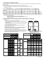
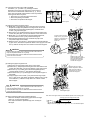
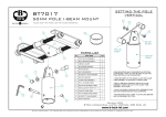
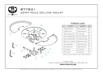
Mitsubishi Electric Air Conditioner CITY MULTI
CMY-R100VBK, CMY-R200VBK
Twinning Kit Installation Manual
¡For your safety, thoroughly read the following instructions prior to installation.
WT05221X02
Safety Precautions
¡Thoroughly read the following “Safety Precautions” to ensure proper installation.
¡Observe the following important safety precautions at all times.
¡Hazards that can occur from incorrect handling are classified by the symbols below:
WARNING
CAUTION
Incorrect handling can result in death or serious injury.
Incorrect handling can result in bodily injury and/or structure damage.
WARNING
Only a dealer or qualified technician should
perform installation.
Properly install all parts according to the
instructions in the Installation Manual.
¡Improper installation may result in refrigerant gas leakage
and equipment damage.
¡If the wrong twinning pipe or wrong size connecting pipe is
used, air conditioning performance will suffer.
Do not make any modifications or alterations.
Consult your dealer for repair.
When installing or relocating the unit, check
that no substance other than the specified
refrigerant (R410A) enters the refrigerant circuit.
¡Improper installation may result in water leakage, electric shock,
or fire.
¡Any presence of foreign substance or air can cause abnormal
pressure rise or explosion.
In the event of a refrigerant leak, thoroughly
ventilate the room.
After installation, check for a refrigerant leak.
¡If leaked refrigerant comes in contact with a heat source,
such as a fan heater, stove, or electric grill, toxic gases will be
generated.
¡If refrigerant leaks and comes in contact with an open flame,
toxic gases will be generated.
CAUTION
Do not touch the refrigerant pipes and
refrigerant circuit components with bare
hands during and immediately after operation.
Properly dispose of packing materials.
¡Plastic bags can pose suffocation and choking hazards: keep
them out of the reach of children. Tear the plastics bags
before disposing of them.
¡During or immediately after operation, certain parts of the unit
such as pipes and compressor may be either very cold or hot,
depending on the state of the refrigerant in the unit at the
time. To reduce the risk of frostbites and burns, do not touch
these parts with bare hands.
❈ See the Installation Manual that came with the outdoor unit for installation instructions.
1
1. Confirming the Package Contents
The following items are included with the Twinning Kit (CMY-R100VBK, CMY-R200VBK). Verify that all items are present before
starting installation.
❈ Always use the twinning pipes included in the kit when preparing the twinning kit.
If the pipes field-supplied do not fit the parts in the kit, use the accessory piping parts listed below.
(1) Package contents
1Low-pressure 2High-pressure
4Elbow pipe
3Fixing screw
Ø22.2 [7/8]
twinning kit twinning pipe
Model
pipe 8High-pressure pipe
5Elbow pipe 6Elbow pipe 7High-pressure
0 OD19.05 [3/4] A OD22.2 [7/8]
(for routing through (for routing through 9Pipe cover
Ø28.58 [1-1/8] Ø31.75 [1-1/4]
-ID15.88 [5/8]
-ID19.05 [3/4]
the bottom)
the front)
CMY-R100VBK
1
1
2
1
1
-
3
3
1
2
1
CMY-R200VBK
1
1
1
-
1
1
1
1
1
-
-
IPacking
JFixing plate
KInstallation Manual
(this booklet)
U-PIPE
B OD19.05 [3/4] C OD22.2 [7/8] D OD28.58 [1-1/8] E OD31.75[1-1/4] FU-PIPE GID19.05
[3/4] HSaddle
-ID22.2 [7/8] -ID28.58 [1-1/8] -ID22.2 [7/8]
ID25.4 [1] -ID25.4 [1]
-ID34.93 [1-3/8]
Model
LInsulation cover MCable tie
CMY-R100VBK
-
1
-
-
1
1
1
1
1
1
1
2
CMY-R200VBK
2
-
1
1
-
-
-
-
-
1
1
2
(2) List of field-supplied parts
· Refrigerant pipes other than the ones provided in the kit
· Heat-resistant insulation material (for field-supplied refrigerant pipes)
· Insulation cover tape
2. Selecting the Correct Size Refrigerant Pipes and Using the Twinning Kit
(1) Pipe size
1 Field-supply the pipes to be connected to the kit.
2 Choose the correct size pipe using the table below. Connect the fieldsupplied pipe to the twinning kit for the sizes in the table that are marked
with an asterisk (*).
3 If the pipe was cut with a pipe cutter, remove the burrs and eliminate
foreign materials before connecting.
❈ On the low-pressure side, the twinning kit connects to the pipes fieldsupplied inside the outdoor unit.
The distributor on the low-pressure side must be placed in the outdoor unit
that has a larger capacity index of the two, regardless of the relative
positions of the outdoor units or their addresses.
If the distributor is placed in the outdoor unit that has a smaller capacity,
refrigerant will not be properly distributed and compressor failure may result.
( If outdoor units that have the same capacity are used in combination, the
distributor can be placed in either outdoor unit.)
Package unit name
Component unit name
B0
Outdoor unit 2
C0
D0
High-pressure
A
E0
Low-pressure
B
F0
F
PURY-
PURY-
PURY-
Y(S)HM
Y(S)HMU
T(S)HMU
B0
C0
P450
P250
P200
P500
P250
P250
P550
P300
P250
P600
P300
P300
P650
P350
P300
P700
P400
P300
P750
P400
P350
P800
P400
P400
EP400
EP200
EP200
EP450
P250
EP200
EP500
EP300
EP200
EP550
EP300
P250
EP600
EP300
EP300
P144
P72
P72
P168
P96
P72
P192
P96
P96
P216
P120
P96
P240
P120
P120
P144
P72
P72
P168
P96
P72
P192
P96
P96
P216
P120
P96
P240
P120
P120
D0
E
Twinning pipe ~ Outdoor unit
CMY-R200VBK
Low-pressure
C or D
E or F
A1
A2
A3
B1
B2
B3
C1
C2
C3
D1
D2
D3
E1
E2
E3
F0
( Unit : mm [in] )
Ø22.2
[7/8]
CMY-R100VBK
A
To BC controller
Twinning pipe (high pressure)
B
To BC controller
High-pressure
Unit model
E0
D
C
( Unit : mm [in] )
A0
Outdoor unit 2
Twinning Kit (low pressure)
A0
Outdoor unit 1
Outdoor Twinning Kit
BC controller ~ Twinning pipe
Outdoor unit 1
Ø28.58(*)
[1-1/8]
Ø28.58(*)
[1-1/8]
Ø22.2
[7/8]
CMY-R100VBK
Ø28.58
[1-1/8]
PURY-
YHM
Ø34.93(*)
[1-3/8]
Ø28.58
[1-1/8]
Ø28.58(*)
[1-1/8]
Ø22.2
[7/8]
CMY-R100VBK
Ø28.58
[1-1/8]
PURY-
YHMU
C1
D1
E1
A2
B2
C2
D2
E2
A3
B3
C3
D3
E3
P200
P250
P300
P350
P400
Ø15.88(*)
[5/8]
Ø19.05
[3/4]
Ø19.05
[3/4]
Ø19.05
[3/4]
Ø22.2(*)
[7/8]
Ø19.05(*)
[3/4]
Ø22.2
[7/8]
Ø22.2(*A)
[7/8]
Ø28.58
[1-1/8]
Ø28.58
[1-1/8]
EP200
EP300
-
-
-
Ø15.88(*)
[5/8]
Ø19.05
[3/4]
-
-
-
Ø19.05(*)
[3/4]
Ø22.2
[7/8]
-
-
-
P72
P96
P120
-
-
Ø15.88(*)
[5/8]
Ø19.05
[3/4]
Ø19.05
[3/4]
-
-
Ø22.2
[7/8]
Ø28.58
[1-1/8]
-
-
Ø19.05 *
[3/4]
Ø28.58 *
[1-1/8]
CMY-R100VBK
B1
( )
( )
Ø22.2
[7/8]
A1
Ø28.58
[1-1/8]
PURY-
THMU
P72
P96
P120
-
-
Ø15.88(*)
[5/8]
Ø19.05
[3/4]
Ø19.05
[3/4]
-
-
Ø22.2
[7/8]
Ø28.58
[1-1/8]
-
-
( )
Ø19.05 *
[3/4]
( )
Ø28.58 *
[1-1/8]
-
*A : In case of CMY-R200VBK
See reverse.
2
(2) Low-pressure twinning kit in CMY-R100VBK
Use either F or G in table 1,(1) Package Contents
depending on the size of the pipe at the control valve on
the unit to be combined with. Attach items H, I, and J
to the stop valve sheet metal and then to the low-pressure
twinning kit to hold it into place.
1. Attach item J to the stop valve sheet metal.
2. Attach the packing and saddle.
3. Secure the low pressure twinning kit.
3
3
1
F or G
H,I,J
Stop valve
Section to be brazed field-supplied
(3) Routing the pipe through the bottom
(1) Braze item 7 high-pressure pipe to the stop valve so that the
dimples on the pipe are parallel to the edge of the cutout hole.
Expand the end of the field-supplied pipes, and braze them
to item 7 high-pressure pipe.
(2) Attach item 1 low-pressure twinning kit to the sheet metal of the
control valve with item 3 screw, and braze it to the control valve.
(3) Braze item 5 or 6 elbow pipe to the field-supplied pipe first,
and then braze it to item 1 low-pressure twinning kit.
(4) Flare the field-supplied pipe end, and braze the pipe to the
low-pressure pipe in the middle.
(5) Wrap the pipe in front of item 1 low-pressure twinning kit with item
9 pipe cover, and attach compressor cables to item 9 pipe cover with
item M cable tie to keep them out of direct contact with the pipes.
1
3
Connect the pipe so that the
dimples on the 7 high pressure
pipe are on an imaginary line
parallel to the edge of the
cutout hole.
CAUTION
· Before heating the pipes, place a wet towel on the control valve to
keep its temperature below 120 ˚C [248˚F].
· Direct the flame away from the cables and sheet metals inside the
unit so as not to burn them.
5,6
Field-supplied
pipes
Field-supplied pipes
9
Wrap the pipe cover here.
Attach compressor cables to
Pipe cover with Cable tie
to keep them out of direct
contact with the pipes.
(4) Routing the pipe through the front
(1) Braze item 8 high-pressure pipe to the control valve.
(2) Attach item 1 low-pressure twinning kit to the sheet metal of the
control valve with item 3 screw, and braze it to the control valve.
(3) Braze item 5 or 6 elbow pipe to the field-supplied pipe first,
and then braze it to item 1 low-pressure twinning kit.
(4) Braze either item 4 or 5 elbow pipe to the low-pressure pipe in
the middle.
(5) Wrap the pipe in front of item 1 low-pressure twinning kit with
item 9 pipe cover, and attach compressor cables to item 9 pipe
cover with item M cable tie to keep them out of direct contact
with the pipes.
3
1
9
Wrap the pipe cover here.
Attach compressor cables to
Pipe cover with Cable tie
to keep them out of direct
contact with the pipes.
CAUTION
· Before heating the pipes, place a wet towel on the control valve to
keep its temperature below 120 ˚C [248˚F].
· Direct the flame away from the cables and sheet metals inside the
unit so as not to burn them.
5,6
8
4,5
Field-supplied pipes
Note. Refer to the figure below for the installation position of the twinning pipe.
(5) Slope of twinning pipes (high-pressure side only)
Make sure the slope of the twinning pipes are at an angle
within ±15˚ to the horizontal plane.
If the slope exceeds the specified angle, the unit may be
damaged.
±15˚
Twinning pipe on the high-pressure side
Slope of the twinning pipe is at an angle within ±15˚ to the horizontal plane.
3
(6) The length of the straight pipe between indoor units and the twinning pipe (high-pressure pipe)
Use the pipes supplied in the twinning kit, and make sure the section of the field-supplied pipe that connects to the twinning
pipe has at least 500 mm [19-11/16 in] of straight section. (The section of the field-supplied pipe that connects to the twinning
pipe must have at least 500 mm [19-11/16 in] of straight section.) If the straight section is less than 500 mm [19-11/16 in],
it may result in equipment damage.
(7) Pipe connection (high-pressure side)
Make sure pipes from the twinning pipe to the outdoor unit are sloped downwards.
Outdoor unit 1
100mm [4 in]
or more
Downward slope
A
B
Outdoor unit 2
To BC controller
To BC controller
Upward slope
High-pressure
twinning pipe
High-pressure twinning pipe
Total pipe length = A + B < 5m [16-7/16 ft]
To indoor unit
200mm max.
· If high-pressure twinning pipe is installed above the base of the
outdoor unit, it should be no more than 200mm [7-7/8 in].
3. Pipe Connection Example
Connect the pipes between outdoor units,
using the figure below as a reference.
1Low-pressure twinning kit
Low-pressure connecting pipe
(field-supplied)
High-pressure connecting pipe
(field-supplied)
2High-pressure twinning pipe
Main low-pressure pipe (field-supplied)
Main high-pressure pipe (field-supplied)
4. Insulation Cover Installation
Install the insulation cover on the twinning kit after brazing the pipes and twinning kit.
Insulate all refrigerant pipes. Insulate the high-pressure and low-pressure pipes separately, and pipes located inside the unit as well as
the outside. Use heat-resistant insulation material (Heat resistant : at least 120˚C [248˚F], Thickness: high-pressure = 10 mm [13/32 in],
low-pressure = 20 mm [13/16 in] ). Position the edges of the insulation cover and heat-resistant insulation material so as not to leave a
gap, and then wrap the exterior perimeter of the pipe joints and middle with tape (field-supplied).
Heat-resistant insulation material (field-supplied)
Tape (field-supplied)
field-supplied pipe
field-supplied pipe
2High-pressure
twinning pipe field-supplied pipe
To be gap free
To be gap free
LInsulation cover
Heat-resistant insulation material (field-supplied)
Insulation cover
Heat-resistant insulation material (field-supplied)
Overlap margin of the tape
Insulation covers can shrink.
Overlap the tape as shown in the left
figure so that there will be no gap in
between the insulation cover or
field-installed insulation material.
Tape (field-supplied)
5. Miscellaneous Notes
Secure the field-supplied pipes with a pipe cover and a cable tie in place to keep them from coming in contact with other pipes as
necessary.
WT05221X02
See reverse.
4