Download Mitsubishi Electronics LT-4260 User's Manual
Transcript
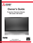
Owner’s Guide
LCD Television System
LT-4260
(LCD Display model: L423FR)
visit our website at
www.mitsubishi-tv.com
CAUTION
RISK OF ELECTRIC SHOCK DO NOT OPEN
CAUTION:
TO REDUCE THE RISK OF ELECTRIC SHOCK, DO NOT REMOVE COVER OR BACK.
NO USER SERVICEABLE PARTS INSIDE.
REFER SERVICING TO QUALIFIED SERVICE PERSONNEL.
The lightning flash with arrowhead symbol within an equilateral triangle is intended to alert the
user of the presence of uninsulated “dangerous voltage” within the product’s enclosure that may be
sufficient magnitude to constitute a risk of electric shock.
The exclamation point within an equilateral triangle is intended to alert the user to the presence of
important operating and maintenance (servicing) instructions in the literature accompanying the
product.
Note: This equipment has been tested and found to comply with the limits for a Class B digital device, pursuant to part 15
of the FCC Rules. These limits are designed to provide reasonable protection against harmful interference in a residential
installation. This equipment generates, uses and can radiate radio frequency energy and, if not installed and used in
accordance with the instructions, may cause harmful interference to radio communications. However, there is no guarantee
that interference will not occur in a particular installation. If this equipment does cause harmful interference to radio or
television reception, which can be determined by turning the equipment off and on, the user is encouraged to try to correct
the interference by one or more of the following measures:
• Reorient or relocate the receiving antenna.
• Increase the separation between the equipment and the receiver.
• Connect the equipment into an outlet on a circuit different from that to which the receiver is connected.
• Consult the dealer or an experienced radio/TV technician for help.
Product Name: Liquid Crystal High Definition TV system
CAUTION:
To assure continued FCC compliance, the user must use a shielded video interface cable with bonded ferrite cores at both
ends, when using the MonitorLink™/HDMI™ input.
Changes or modifications not expressly approved by Mitsubishi could void the user’s authority to operate this
equipment.
WARNING:
TO REDUCE THE RISK OF FIRE OR ELECTRIC SHOCK, DO NOT EXPOSE THIS PRODUCT TO RAIN
OR MOISTURE.
CAUTION:
TO PREVENT ELECTRIC SHOCK, MATCH WIDE BLADE OF PLUG TO WIDE SLOT, FULLY INSERT.
NOTE TO CATV SYSTEM INSTALLER:
THIS REMINDER IS PROVIDED TO CALL THE CATV SYSTEM INSTALLER’S ATTENTION TO ARTICLE
820-40 OF THE NEC THAT PROVIDES GUIDELINES FOR THE PROPER GROUNDING AND, IN PARTICULAR,
SPECIFIES THAT THE CABLE GROUND SHALL BE CONNECTED TO THE GROUNDING SYSTEM OF THE
BUILDING, AS CLOSE TO THE POINT OF CABLE ENTRY AS PRACTICAL.
Hg LAMP(S) INSIDE THIS PRODUCT CONTAIN MERCURY AND MUST BE RECYCLED OR DISPOSED OF
ACCORDING TO LOCAL, STATE OR FEDERAL LAWS.
Contents
Important Safeguards .................................................................................................................. 4
Cleaning Your LCD Television System ........................................................................................ 7
Chapter 1
Television System Overview
Chapter 2
Television System Setup
Chapter 3
Connections
Chapter 4
Remote Control Functions
Chapter 5
Menu Screen Operations
Chapter 6
Special Features
Thank You ................................................................................................................................... 9
Unpacking Your New TV System ................................................................................................ 10
Special Features ........................................................................................................................... 11
Side Control Panel and Card Reader ............................................................................................ 12
Side Panel Input/Output .............................................................................................................. 13
Attaching HD-6000 to 42" LCD Display ................................................................................... 15
Set-Back Configuration Setup ..................................................................................................... 16
Connecting a Computer ...................................................................................................... 20
Stand Alone Configuration Setup ................................................................................................ 21
Connecting a Computer ...................................................................................................... 22
Wall Mount Configuration Setup ................................................................................................ 23
Connecting a Computer ...................................................................................................... 27
Connecting a VCR to the LCD Side Panel .................................................................................. 29
Connecting an Audio Receiver .................................................................................................... 30
Connecting a DVD Player or Other S-Video Device ................................................................... 31
Connecting a Satellite Receiver/Cable Box................................................................................... 32
Connecting a Computer .............................................................................................................. 33
How Connections Affect the PIP and POP ................................................................................. 34
Overview of the TV Layer Buttons .............................................................................................. 37
Operation .................................................................................................................................... 38
Sleep Timer ................................................................................................................................. 39
Use With Other A/V Products .................................................................................................... 40
Operation of PIP, POP & Double Window ................................................................................. 42
The ViewPoint® Menu System .................................................................................................... 45
MAIN Menu ............................................................................................................................. 47
SETUP Menu .............................................................................................................................. 48
ADVANCED FEATURES Menu ............................................................................................... 50
AUDIO/VIDEO SETTINGS Menu ........................................................................................... 52
Available On-Screen Format Sizes.........................................................................................................57
Operation of PIP and POP and Double Window ........................................................................ 60
Appendix A: HD Input Connection Compatibility ..................................................................... 61
Appendix B: Supported PC Resolutions....................................................................................... 61
Appendix C: Remote Control Programming Codes..................................................................... 62
Appendix D: Media Command™ and Media Card Playback ..................................................... 64
Cable Management ...................................................................................................................... 66
Index............................................................................................................................................ 67
Troubleshooting ........................................................................................................................... 69
Warranty...................................................................................................................................... 74
IMPORTANT SAFEGUARDS
Please read the following safeguards carefully before using this product and retain for future reference.
Always follow all warnings and instructions marked on the product.
1.
Read, Retain and Follow All Instructions
2.
Heed Warnings
3.
Read all safety and operating instructions before operating the product. Retain the safety and operating instructions
for future reference. Follow all operating and use instructions.
Adhere to all warnings on the product and in the operating instructions.
Cleaning
Unplug the product from the wall outlet before cleaning. Do not use liquid, abrasive, or aerosol cleaners. Cleaners
can permanently damage the cabinet and screen. Use a lightly dampened cloth for cleaning.
4.
Attachments and Equipment
5.
Water and Moisture
6.
Accessories
Never add any attachments and/or equipment without approval of the manufacturer as such additions may result in
the risk of fire, electric shock or other personal injury.
Do not use the product where contact with or immersion in water is possible. Do not use near bath tubs, wash bowls,
kitchen sinks, laundry tubs, swimming pools, etc.
Do not place the product on an unstable cart, stand, tripod, or table. The product may fall, causing
serious injury to a child or adult and serious damage to the product. Use only with a cart, stand,
tripod, bracket, or table recommended by the manufacturer, or sold with the product. Any mounting
of the product should follow the manufacturer’s instructions, and should use UL 1678 listed wall
mounting brackets suitable for the weight and mounting surface used.
The product and cart combination should be moved with care. Quick stops, excessive force, and
uneven surfaces may cause the product and cart combination to overturn.
7.
Ventilation
8.
Power Source
9.
Slots and openings in the cabinet are provided for ventilation and to ensure reliable operation of the product and to
protect it from overheating. Do not block these openings or allow them to be obstructed by placing the product on
a bed, sofa, rug, or other similar surface. Nor should it be placed over a radiator or heat register. If the product is
to be placed in a rack or bookcase, ensure that there is adequate ventilation and that the manufacturer’s instructions
have been adhered to.
This product should be operated only from the type of power source indicated on the marking label. If you are not
sure of the type of power supplied to your home, consult your appliance dealer or local power company. The socketoutlet shall be installed near the equipment and shall be easily accessible.
Grounding or Polarization
This product is equipped with a three-wire grounding-type plug, a plug having a third grounding pin. This plug
will only fit into a grounding-type power outlet. This is a safety feature. If you are unable to insert the plug fully
into the outlet, contact your electrician to replace your obsolete outlet. Do not defeat the safety purpose of the
grounding-type plug.
10. Power-Cord Protection
Power-supply cords should be routed so that they are not likely to be walked on or pinched by items placed upon or
against them, paying particular attention to cords at plugs, convenience receptacles, and the point where they exit
from the product.
11. Lightning
For added protection for this product during a lightning storm, or when it is left unattended and unused for long
periods of time, unplug it from the wall outlet and disconnect the antenna or cable system. This will prevent
damage to the product due to lightning and power-line surges.
4
IMPORTANT SAFEGUARDS, continued
12. Power Lines
An outside antenna system should not be located in the vicinity of overhead power lines or other electric, light or
power circuits, or where it can fall into such power lines or circuits. When installing an outside antenna system,
extreme care should be taken to keep from touching such power lines or circuits as contact with them might be fatal.
13. Overloading
Do not overload wall outlets, extension cords or integral convenience receptacles as this can result in a risk
of fire or electric shock.
14. Object and Liquid Entry
Never push objects of any kind into this product through openings as they may touch dangerous voltage points or
short-out parts that could result in fire or electric shock. Never spill liquid of any kind on or into the product.
15. Outdoor Antenna Grounding
If an outside antenna or cable system is connected to the product, be sure the antenna or cable system is grounded so
as to provide some protection against voltage surges and built-up static charges.
Section 810 of the National Electric Code, ANSI/NFPA No. 70, provides
information with respect to proper grounding of the mast and supporting structure,
grounding of the lead in wire to an antenna discharge unit, size of grounding
conductors, location of antenna discharge unit, connection to grounding electrodes,
and requirements for the grounding electrode.
16. Servicing
Do not attempt to service this product yourself as opening or removing covers may
expose you to dangerous voltage or other hazards. Refer all servicing to qualified
service personnel.
EXAMPLE OF ANTENNA GROUNDING
ANTENNA
LEAD IN WIRE
GROUND CLAMP
ELECTRIC
SERVICE
EQUIPMENT
ANTENNA
DISCHARGE UNIT
(NEC SECTION 810-20)
GROUNDING
CONDUCTORS
(NEC SECTION 810-21)
GROUND CLAMPS
NEC — NATIONAL ELECTRICAL CODE
POWER SERVICE GROUNDING
ELECTRODE SYSTEM
(NEC ART 250, PART H)
17. Damage Requiring Service
Unplug the product from the wall outlet and refer servicing to qualified service personnel under the following
conditions:
(a) When the power-supply cord or plug is damaged.
(b) If liquid has been spilled, or objects have fallen into the product.
(c) If the product has been exposed to rain or water.
(d) If the product does not operate normally by following the operating instructions, adjust only those controls that
are covered by the operating instructions as an improper adjustment of other controls may result in damage and will
often require extensive work by a qualified technician to restore the product to its normal operation.
(e) If the product has been dropped or the cabinet has been damaged. The liquid crystal display used in this product
is made of glass. It can break if dropped. Do not come in contact with the liquid crystals or glass in case the LCD
display breaks.
(f) When the product exhibits a distinct change in performance - this indicates a need for service.
18. Replacement Parts
When replacement parts are required, be sure the service technician has used replacement parts specified by the
manufacturer or have the same characteristics as the original part. Unauthorized substitutions may result in fire,
electric shock or other hazards.
19. Safety Check
Upon completion of any service or repair to the product, ask the service technician to perform safety checks to
determine that the product is in safe operating condition.
20. Heat
The product should be situated away from heat sources such as radiators, heat registers, stoves, or other products
(including amplifiers) that produce heat. Do not place this product in an enclosed place (bookcase or wall) without
proper ventilation. Do not block the vents or openings on this product.
5
IMPORTANT SAFEGUARDS, continued
21. Transport/Handling
(a) Be sure to use another person to lift or carry this product. It is recommended that the product be carried by two
people holding it with both of their hands — one hand on each side of the product.
(b) Use caution when transporting the product. Be sure that items such as belt buckles, watches, shirt buttons, and
zippers do not scratch or rub the screen or cabinet.
(c) Do not grip the cut-outs shown in Diagram 1. These cut-outs are not handles.
Diagram 1.
DO NOT USE AS HANDLES
22. LCD Monitor
This monitor uses a technology composed of over 2.9 million thin film transistors. It is common to find a few
colored (non-active) “dots” on the screen. Do not be alarmed. This is a result of the manufacturing process found in
all panels. Your picture performance will not be affected.
23. Wall or Ceiling Mounting
The product should be mounted to a wall or ceiling only as recommended by the manufacturer. When mounting
the LCD display to a wall or ceiling, the stand and Set-Back Box (HD-6000) must be removed from the back of the
LCD display.
CAUTION
This product needs to be attached to the included stand or other optional mounting hardware.
Use the following optional accessories. Use with other optional accessories is capable of resulting in
instability causing possible injury.
Manufacturer’s name: Mitsubishi Digital Electronics America, Inc.
Tilt Wall Mount: LMOUNT-42T
To order LMOUNT-42Ts, please call our Parts Department at (800)553-7278.
Please contact Mitsubishi Digital Electronics America, Inc for approved optional accessories.
6
CLEANING
Cleaning
General Cleaning Warnings :
Normally, light dusting with a dry, non-scratching
duster will keep your product clean. If cleaning
beyond this is needed, please use the following
guidelines:
• DO NOT allow liquid to enter the product through
the ventilation slots or any crevice.
• DO NOT use any strong or abrasive cleaners as
these can scratch the surfaces.
First, turn off the product and unplug the power cord
from the power outlet.
• DO NOT use any commercial cleaners with
ammonia, bleach, alcohol, benzine, or thinners as
these can dull the surfaces.
Top and Sides of the Display:
• DO NOT spray liquids or cleaners directly on the
product’s surfaces.
•
Gently wipe down your product with a soft, nonabrasive cloth such as cotton flannel or a clean
cloth diaper, lightly moistened with water. Dry
with a second dry, soft, non-abrasive cloth.
• DO NOT scrub or rub the product harshly. Wipe
it gently.
• Excessive moisture or water may damage your
product. Use caution when wiping your product.
DO NOT use any kind of abrasive or
liquid cleaner on the surface of the TV
Display.
For further information, please call
Consumer Relations at:
800-332-2119
ENVIRONMENTAL CONDITIONS
Operating
Temperature: 5 - 35 deg C
Humidity: 30 - 80% relative (without condensation)
Storage
Temperature: 20 - 50 deg C
Humidity: 10 - 90% relative (without condensation)
7
Chapter . . .
Television System Overview
Thank You .................................................................................................................. 9
Unpacking Your New TV System ............................................................................. 10
Special Features ......................................................................................................... 11
Side Control Panel and Card Reader ......................................................................... 12
Side Panel Input/Output ........................................................................................... 13
1
Thank You for Your Purchase
Welcome to the wonderful and exciting world of digital television! We are honored that you chose Mitsubishi
as your premier home entertainment partner. The development team at Mitsubishi Digital Electronics America
(MDEA) understands that our customers demand and expect the very best. MDEA was founded on the
core beliefs and philosophies that drive us to deliver products that implement the latest in advanced television
technology.
While some televisions are destined for obsolescence in the near future, MDEA’s televisions are all HDupgradeable. This cornerstone of your home entertainment system will continue to provide unparalleled
enjoyment for years to come!
Whether this is your first Mitsubishi consumer electronics product or another addition to your growing
Mitsubishi system, we hope that this television will bring you many hours of enjoyment.
9
Unpacking Your New TV System
Please take a moment to review the following list of items to ensure that you have received everything below:
MOA01-01
Please send other correspondence to:
Enter the
PRODUCT REGISTRATION
Register your purchase and you’ll be
automatically entered for a chance to win
$5,000, $25,000 or even $50,000!
$100,000 Give Away V
OFFICIAL SWEEPSTAKES RULES: NO PURCHASE NECESSARY TO WIN. Sweepstakes is sponsored by a number of different
companies, will be offered in a number of different presentations, and will award the following prizes: one 1st Prize of $50,000; one 2nd Prize of
$25,000; and five 3rd Prizes of $5,000. Sweepstakes begins May 19, 2003, and ends December 31, 2005. Enter by completing this product
registration or a 3" x 5" card with your name, address, city, state, ZIP Code, and the words “$100,000 Give Away V” and mail to P.O. Box
174268, Dept. MOA, Denver, CO 80217-4268. Entries must be received no later than December 31, 2005, and are limited to one per household.
Mechanically reproduced entries not acceptable. Not responsible for late, lost or illegible entries. A random drawing held in January 2006, will
select the winners from all entries collectively received by the sponsoring companies. Odds of winning depend on the number of eligible entries
received from all sponsors’ presentations. Open to U.S. residents at least 18 years old, except employees and their families of the sweepstakes
judge, all of the sponsoring companies, and their respective subsidiaries. Each winner must submit a signed and notarized affidavit of eligibility
within a specified time after being notified of their prospective winner status, and if a satisfactory affidavit is not received within the stated time,
a new winner will be selected. By submitting an entry, winner agrees to the use of their name, address, and photograph for advertising/publicity
purposes without compensation. All entries become the property of the sweepstakes judge. No transfer or substitution of prize is allowed.
Winner is solely responsible for all taxes. All federal, state and local laws apply. Offer void in Florida and where prohibited by law. For notice of
sweepstakes winners, send a self-addressed, stamped envelope to: “$100,000 Give Away V”, P.O. Box 173133, Denver, CO 80217-3133.
(1) AC Cord
(1) RS-232C Cable
(1) HDMI Cable
(2) AA Batteries
(1) Remote Control
(1) Registration Card
(1) HD-6000
Owner’s Guide
(1) HD-6000 Digital Cable Ready
HDTV Receiver/Controller
(4) Tie Wraps
(1) Cable Management cover
(8) M4 Bolts
(2) M3 Bolts
(4) Mounting Hooks
(1) AC Cord
(1) USB Cable
(1) Registration
Card
(1) Owner’s Guide
for LT-4260
(1) LCD Display
First-Class
Postage
Required
Post Office will
not deliver
without proper
postage.
Mitsubishi Digital Electronics America, Inc.
9351 Jeronimo Rd.
Irvine, CA 92618-1904
P O BOX 174268
DENVER CO 80217-4268
!802174268688!
Included in the HD-6000 carton are the following items:
POWER
PRODUCT REGISTRATION
10
Special Features
Your new LT-4260 High Definition Television System has many special features. This makes it the perfect
control center for your home entertainment system. These special features include:
Multiple Connection Capability
On the HD-6000 back panel you will find a full complement of the connections needed for the most
sophisticated home theater system. Included are standard Audio/Video/S-Video, wideband component video,
FireWire®, IEEE 1394, CableCARD™ and both an HDMI™ Input and an HDMI™ Output.
TV Disc Internal Digital Video Recorder (DVR)
TV Disc is an internal 120GB high definition hard disk drive recorder (also called a digital video recorder or
DVR). It is able to record digital and analog programs received from CableCARD™ channels, Antenna 1,
Antenna 2, devices connected to Input 1, 2 or IEEE 1394 devices. This exciting feature may record as much
as 12 hours of high definition TV programming and includes live TV pause with instant replay. Now you
can record a high definition program and watch it later without any picture quality loss and without a VCR.
Recordings on the TV Disc can be sent by IEEE 1394 to D-VHS VCRs or to other IEEE 1394 compatible
TVs. When recording analog programs, TV Disc will even use Dolby Digital® Record to convert the analog
stereo to high quality digital stereo compatible with Dolby Digital® decoding surround receivers.
Digital Cable Ready (CableCARD™)
Your widescreen Mitsubishi HDTV receiver/controller is "Plug-and-Play" ready. It can descramble a cable
provider's one-way digital signals with the use of a CableCARD™ security module. The CableCARD™ is
used in place of a traditional cable box to access digital cable programming (including high definition). Contact
your local cable provider for availability information and service details.
NetCommand® Home Network Control System
Your Mitsubishi HDTV receiver/controller offers a new level of networking to combine selected older products
with new and future digital products. NetCommand supports IEEE 1394 connections, Audio Video Control
system (AV/C), 5C copy protection and IR control of selected older products such as VCRs, DVD players,
cable boxes or satellite receivers. NetCommand includes the ability to learn remote control signals directly from
many devices, allowing you to customize the NetCommand system in a way that works best for your viewing.
LT-4260
The HD-6000 is designed to work with all of the features of the Mitsubishi LT-4260 LCD HDTV display.
11
Side Control Panel and Card Reader
Many remote control buttons are duplicated on the side control panel. Please see Remote Control Functions,
page 37, for an explanation of their usage.
(left side of LCD Display)
(right side of LCD Display)
CARD 1 MMC & SD™
CARD 3 Compact Flash®
CARD 2 SmartMedia™
CARD 4 Memory Stick®
GUIDE
See Media Card Playback,
Page 64, For Details.
The ADJUST, ENTER, MENU, and CANCEL buttons may be used to access or navigate through the screen menus
12
Side Panel Input/Output
�����������������������
������������
�����������������������
������������
�
�
�
�
�
�
�
�����
�
6. PC Audio Input
This is used to send the sound from a computer to the LCD
Displays speakers.
�
��
1. Headphone
The Headphone Output sends the LCD Displays connected
audio signals to a pair of headphones. The audio output from
the TV’s speakers will be unavailable.
2. Audio Out
The Audio Output sends the LCD Displays connected audio
signals to an A/V receiver or other equipment.
3. Composite Input
These inputs can be used for the connection of a VCR, Super
VHS (S-VHS) VCR, laser disc player, or other A/V device to
the TV. With each input, you may connect to the S-VIDEO
or VIDEO terminal but not to both.
4. Component Input
This input can be used for the connection of A/V equipment
with component video outputs, such as a DVD player or
compatible Video Game System. Please see Appendix A, page
61, for signal compatibility.
7. HDMI™/MonitorLink™ Input
This is a Mitsubishi-exclusive proprietary digital interface for
the display of high quality digital video signals from Mitsubishi
products such as the HD-6000 HDTV Receiver/Controller.
All video signals, both analog and digital are sent digitally to
your Mitsubushi TV. Can also be used as a HDMI™ input
for other compatible sources.
Note: The HDMI™-HDTV input terminal is compliant
with the EIA-861 standard and is not intended for use with
personal computers.
8. MonitorLink™ control/RS-232C for HD-6000
A digital control interface that works in parallel with
MonitorLink™. While MonitorLink™ provides the digital
video signal, MonitorLink™ Control provides enhanced
functioning such as automatic power ON/OFF and input
selection. Can also be used with other compatible RS-232C
external devices. Please visit www.mitsubishi-tv.com for more
information or RS-232C command structure.
9. Authorized Card Reader
This USB input connects only to the HD-6000 and enables
the use of the media card reader located on the LCD Display
side panel. See Page 64 for details.
CAUTION
5. PC Input
This input can be used for analog RGB signals from a
personal computer. Supported resolutions include VGA,
SVGA, XGA, and WXGA only. Please see Appendix B, page
61 for supported PC Resolutions.
13
DO NOT CONNECT ANY USB
DEVICE TO THIS INPUT.
10. DVI Audio Input
Use this input to provide sound when an HDMI to DVI
adapter is used.
Chapter . . .
Television System Setup
Attaching HD-6000 to 42" LCD Display ................................................................. 15
Set-Back Configuration Setup ................................................................................... 16
Connecting a Computer ............................................................................................ 20
Stand Alone Configuration Setup ............................................................................. 21
Connecting a Computer ............................................................................................ 22
Wall Mount Configuration Setup ............................................................................. 23
Connecting a Computer ............................................................................................ 27
2
Television System Setup
The LT-4260 LCD Television System is extremely versatile. The System includes a 42" LCD Display and
a HD-6000 Digital Cable Ready HDTV Receiver/Controller. To take full advantage of all the features this
system has to offer, attach the HD-6000 to the 42" LCD Display.
Attaching HD-6000 to 42" LCD Display
The HD-6000 can be connected to the 42" LCD Display by one of the following methods.
Set-Back Configuration
Stand Alone Configuration
Wall Mount Configuration
When the HD-6000 is connected to the 42" LCD,
the HD-6000 front control buttons are inactive.
To control the HD-6000 (and 42" LCD), set the
remote control to the CABLE/DBS/DTV Layer
or use control buttons located on the side of the
LCD Display.
2
15
4
Set-Back Configuration Setup
CAUTION
• Do not remove the stand.
• The Display is heavy. Move it with two or more people.
1. Place the 42" LCD Display on a sturdy surface.
2. Remove the HD-6000 Receiver/Controller from its carton.
3. Remove the protective material from around the HD-6000 and place it on a sturdy surface.
4. Turn the HD-6000 over so that the bottom is facing up and gently place it on the protective material.
5. Attach the 4 Mounting Hooks.
����������������
When the HD-6000 is connected to the 42" LCD,
the HD-6000 front control buttons are inactive.
To control the HD-6000 (and 42" LCD), set the
remote control to the CABLE/DBS/DTV Layer
or use control buttons located on the side of the
LCD Display.
16
Set-Back Configuration Setup (continued)
6. Grasp the HD-6000 from the top and bottom. Slide the HD-6000 into place making sure that all 4
mounting hooks connect to the corresponding pin located on the LCD Display stand.
PIN ON LCD Display
HOOK ON HD6000
PIN ON LCD Display
HOOK ON HD6000
HOOK ON HD6000
PIN ON LCD Display
HOOK ON HD6000
PIN ON LCD Display
17
Set-Back Configuration Setup (continued)
7. Secure the HD-6000 to the stand using the two M3 Bolts.
18
Set-Back Configuration Setup (continued)
8. Connect the HDMI™ Cable from the HDMI™ Output connector on the back of the HD-6000 to the
HDMI™/MonitorLink Input connector located on the back of the LCD Display.
HD-6000 Back Panel (section detail)
LCD Display Back Panel (section detail)
9. Connect the USB Cable from the Authorized Card Reader connector on the back of the HD-6000 to
the AUTHORIZED CARD READER connector on the back of the LCD Display.
HD-6000 Back Panel (section detail)
LCD Display Back Panel (section detail)
10. Connect the RS-232C Cable from the MonitorLink™ Control RS-232C connector on the back of
the HD-6000 to the RS-232C/MonitorLink™ Control for HD-6000 connector on the back of the
LCD Display.
HD-6000 Back Panel (section detail)
19
LCD Display Back Panel (section detail)
Set-Back Configuration Setup (continued)
11. Connect the AC Power Cord from the back of the HD-6000 to the back of the LCD Display.
HD-6000 Back Panel (section detail)
LCD Display Back Panel (section detail)
12. Connecting a Computer (OPTIONAL)
• Your Mitsubishi LCD display supports VGA, SVGA,
XGA, and WXGA PC resolutions only.
See Appendix B: Supported PC Resolutions, P. 61
When connecting a PC to the LCD
Television System, connect the PC directly
to the LCD display. Do not connect the PC
to the HD-6000.
a. Connect a Mini D-sub 15-pin (RGB) cable from
the LCD Display back panel to PC or Macintosh®
LCD Display Side Panel
back panel.
b. Connect a PC Audio Cable (or 1/8” stereo
mini jack cable) from the LCD side panel to
PC or Macintosh back panel.
LCD Display Back Panel (section detail)
to PC or Macintosh® back panel
�
�
to PC or Macintosh® back panel
Figure 7. Connecting Computer
13. Refer to Chapter 2 (in the HD-6000 Owner's Guide) on how to connect A/V equipment (DVD player,
Cable Box, etc) to the back panel of the HD-6000.
14. Refer to HD-6000 Owner’s Guide for complete operating instructions. The HD-6000 controls all
features that the LCD HDTV system has to offer.
20
Stand Alone Configuration Setup
CAUTION
• Do not remove the stand.
• The Display is heavy. Move it with two or more people.
1. Place the 42" LCD Display on a sturdy surface.
2. Remove the HD-6000 Receiver/Controller from its carton.
3. Place the HD-6000 Receiver/Controller on a sturdy surface.
When the HD-6000 is connected to the 42" LCD,
the HD-6000 front control buttons are inactive.
To control the HD-6000 (and 42" LCD), set the
remote control to the CABLE/DBS/DTV Layer
or use control buttons located on the side of the
LCD Display.
4. Connect the HDMI™ Cable from the HDMI™ Output connector on the back of the HD-6000 to
the HDMI™/MonitorLink™ INPUT connector located on the back of the LCD Display.
HD-6000 Back Panel (section detail)
LCD Display Back Panel (section detail)
5. Connect the USB Cable from the Authorized Card Reader connector on the back of the HD-6000 to
the AUTHORIZED CARD READER connector on the back of the LCD Display.
HD-6000 Back Panel (section detail)
LCD Display Back Panel (section detail)
6. Connect the RS-232C Cable from the MonitorLink™ Control RS-232C connector on the back
of the HD-6000 to the RS-232C/MonitorLink™ Control for HD-6000 connector on the back of the
LCD Display.
HD-6000 Back Panel (section detail)
21
LCD Display Back Panel (section detail)
Stand Alone Configuration Setup (continued)
7. Connect the AC Power Cord from the back of the HD-6000 to the back of the LCD Display.
HD-6000 Back Panel (section detail)
LCD Display Back Panel (section detail)
8. Connecting a Computer (OPTIONAL)
• Your Mitsubishi LCD display supports VGA, SVGA,
XGA, and WXGA PC resolutions only.
See Appendix B: Supported PC Resolutions, P. 61
When connecting a PC to the LCD
Television System, connect the PC directly
to the LCD display. Do not connect the PC
to the HD-6000.
a. Connect a Mini D-sub 15-pin (RGB) cable from
the LCD Display back panel to PC or Macintosh®
LCD Display Side Panel
back panel.
b. Connect a PC Audio Cable (or 1/8” stereo
mini jack cable) from the LCD Display
side panel to PC or Macintosh back panel.
LCD Display Back Panel (section detail)
to PC or Macintosh® back panel
�
�
to PC or Macintosh® back panel
Figure 7. Connecting Computer
9. Refer to Chapter 2 (in the HD-6000 Owner's Guide) on how to connect A/V equipment (DVD player,
Cable Box, etc) to the back panel of the HD-6000.
10. Refer to HD-6000 Owner's Guide for complete operating instructions. The HD-6000 controls all
features that the LCD HDTV system has to offer.
22
Wall Mount Configuration Setup
CAUTION
• Mitsubishi recommends that only qualified service personnel mount the LCD display. Customers
should not attempt to do the work themselves. Mitsubishi bears no responsibility for improper
mounting or mounting that results in an accident or injury.
• Carefully read the installation instructions that come with the wall mount before starting
installation.
1. Before performing work make sure to disconnect the AC Power cord from the 42" LCD Display.
2. Before performing work spread the protective sheet, which was wrapped around the display, on a flat,
even surface. This will prevent the display from being damaged.
3. Gently lay the LCD Display face down on the protective sheet.
4. Do not touch or hold the screen face while carrying the display.
5. Remove the screws indicated by the arrows. Remove the stand cover.
����������������
23
When the HD-6000 is connected to the 42" LCD,
the HD-6000 front control buttons are inactive.
To control the HD-6000 (and 42" LCD), set the
remote control to the CABLE/DBS/DTV Layer
or use control buttons located on the side of the
LCD Display.
Wall Mount Configuration Setup (continued)
CAUTION
Be sure to use another person to hold or support the stand while removing the screws.
The stand can easily fall resulting in injury or damage.
6. Remove the Screws indicated by the arrows.
����������������
24
Wall Mount Configuration Setup (continued)
7. Slide the stand in the direction indicated by the arrows and remove it.
CAUTION
When the Stand's Metal Hooks (Right and Left) are unlocked, the Stand can easily fall resulting in
injury or damage.
�����
�����������
����������������
8. The LCD Display is now ready to mount.
9. Connect the HDMI™ Cable from the HDMI™ Output connector on the back of the HD-6000 to the
HDMI™/MonitorLink INPUT connector located on the back of the LCD Display.
HD-6000 Back Panel (section detail)
LCD Display Back Panel (section detail)
10. Connect the USB Cable from the Authorized Card Reader connector on the back of the HD-6000 to
the AUTHORIZED CARD READER connector on the back of the LCD Display.
HD-6000 Back Panel (section detail)
25
LCD Display Back Panel (section detail)
Wall Mount Configuration Setup (continued)
11. Connect the RS-232C Cable from the MonitorLink Control RS-232C connector on the back of the
HD-6000 to the RS-232C/MonitorLink Control for HD-6000 connector on the back of the LCD
Display.
HD-6000 Back Panel (section detail)
LCD Display Back Panel (section detail)
12. Connect the AC Power Cord from the back of the HD-6000 to the back of the LCD Display.
HD-6000 Back Panel (section detail)
LCD Display Back Panel (section detail)
26
Wall Mount Configuration Setup (continued)
13. Connecting a Computer (OPTIONAL)
• Your Mitsubishi LCD display supports VGA, SVGA,
XGA, and WXGA PC resolutions only.
See Appendix B: Supported PC Resolutions, P. 61
a. Connect a Mini D-sub 15-pin (RGB) cable from
the LCD Display Back panel to PC or Macintosh®
back panel.
When connecting a PC to the LCD Television
System, connect the PC directly to the LCD
display. Do not connect the PC to the HD-6000.
b. Connect a PC Audio Cable (or 1/8” stereo
mini jack cable) from the LCD side panel to
PC or Macintosh back panel.
LCD Display Side Panel
LCD Display Back Panel (section detail)
to PC or Macintosh® back panel
�
�
to PC or Macintosh® back panel
Figure 7. Connecting Computer
14. Refer to Chapter 2 (in the HD-6000 Owner's Guide) on how to connect A/V equipment (DVD player,
Cable Box, etc) to the back panel of the HD-6000.
15. Refer to HD-6000 Owner’s Guide for complete operating instructions. The HD-6000 controls all
features that the LCD HDTV system has to offer.
27
Chapter . . .
3
Connections
Connecting a VCR directly to LCD Side Panel ............................................................. 29
Connecting an Audio Receiver ...................................................................................... 30
Connecting a DVD Player or Other S-Video Device ..................................................... 31
Connecting a Satellite Receiver/Cable Box.................................................................... 32
Connecting MonitorLink™ or a Computer .................................................................. 33
How Connections Affect the PIP and POP .......................................................................34
Additional connection cables are not provided
with the TV. They should be available at
most electronic stores.
The Display Side Panel is shut-off
when the HD-6000 is connected to the
LCD Display using a HDMI™ cable.
Refer to Chapter 2 in the HD-6000
Owner’s Guide on how to connect A/V
equipment to the HD-6000. The HD6000 does not shutoff the PC INPUT.
Connecting a VCR directly to LCD Side Panel
NOTE: The LCD Display side panel connections shown below can only be used when the HD-6000 is not connected to
the LCD Display.
Composite Video with Audio or SVideo with Audio (Recommended)
����������������������
(Figure 1)
1.
2. Connect a set of audio cables from AUDIO OUT
on the VCR back panel to VIDEO INPUT/
AUDIO RIGHT & LEFT on the LCD Display
side panel.
���
�
�����
�
������������
������������
��
�������
• The red cable connects to the R (right) channel
• The white cable connects to the L (left) channel
�
�����
�
���
�
�
�����
�
�
�
���������
��������
���������
�
�
������
����
����������������������� ���
�������������������� �����
����
�������������������
��������������
Connect a video or a S-Video cable from VIDEO
OUT on the VCR back panel to VIDEO INPUT
on the LCD Display side panel.
�������
�
���
Figure 1. Connecting the VCR Audio/Video.
29
You may connect to the S-VIDEO or VIDEO
terminal but not to both.
Connecting an Audio Receiver Directly to LCD Side Panel
NOTE: The LCD Display side panel connections shown below can only be used when the HD-6000 is not connected to
the LCD Display.
Stereo Audio System
(recommended for shelf units or A/V receivers without
digital audio inputs)
(Figure 2)
1.
����������������������
���
�
Connect the audio cables from AUDIO
OUT on the LCD Display side panel to TV IN or
AUX IN terminals on the back of the audio system.
�����
• The red cable connects to the R (right) channel
• The white cable connects to the L (left) channel
2.
Turn off the LCD Display speakers through the
AUDIO/VIDEO SETTINGS Menu, page 52.
�������������������������������
�
3.
Set the audio system’s input to the TV or AUX
position to hear the LCD Displays audio through a
stereo system.
Additional connection cables are not provided
with the TV. They should be available at most
electronic stores.
�����
���
��
��
���
��
��
������
���
��
������
���
�
�
Figure 2. Connecting the Stereo Audio System.
These types of audio connection do NOT support
multi-channel digital audio. Please refer to your
other devices Owner’s Guide to verify.
A/V Receiver
��������������������������������
�
(Figure 3)
1.
���
Connect either a video cable or a S-Video cable
(but not both) from VIDEO MONITOR OUT
on the back of the A/V receiver to VIDEO INPUT
on the LCD Display side panel.
Connect a set of audio cables from AUDIO OUT
on the LCD Display side panel to AUDIO TV IN
on the back of the A/V receiver.
• The red cable connects to the R (right) channel
• The white cable connects to the L (left) channel
�����
����������������������
�
2.
���������
���
������
���
�
�����
������
������
����
���
�����
����
�
�������
Figure 3. Connecting the A/V Receiver.
Note: Please see your A/V receiver Owner’s Guide for more
detailed connections.
30
Connecting a DVD Player or Other S-Video Device Directly to
LCD Side Panel
NOTE: The LCD Display side panel connections shown below can only be used when the HD-6000 is not connected to
the LCD Display.
DVD Player/Video Game with
Component Video
�
(Figure 4)
���
�����
�
�
�
�
1.
Connect the Component Video cables from
(YCb Cr or Y Pb Pr) VIDEO OUT on the back
of the DVD player to COMPONENT VIDEO
INPUT on the LCD Display side panel. The correct
connections are:
A. Y to Y
B. Cb or Pb to Pb
C. Cr or Pr to Pr
2.
Connect a set of audio cables from AUDIO OUT
on the back of the DVD player to COMPONENT
VIDEO Input/AUDIO RIGHT & AUDIO LEFT
on the LCD Display side panel.
�����������
����������
��������������
�
���������
�
�
�
�
�����
���������������
���
�������������
������
�����
����������
����������
�����
��
�������
�����
�����������������������������������
���������������������������������
�
����������
�
������������
��
�
��������� ��������
���������
�����
��������������
���
������������������������������
�������������
�������
�������
������������������
����������������
�������������
�
Figure 4. Connecting a DVD Player with Component Video.
See Appendix A, page 61, for component video
signal compatibility information.
• The red cable connects to the R (right)channel
• The white cable connects to the L (left) channel
NOTE: Some video game systems support component
connections. Please refer to your video game
console Owner’s Guide.
NOTE: If your DVD player supports progressive
scan playback, be sure to set your player
accordingly. Please refer to your DVD player’s
Owner’s Guide.
For digital audio connections, see your DVD
and A/V receiver Owner’s Guides.
����������������������
Other S-Video Device
(Figure 5)
�
1.
���
�����
�
Connect a set of audio cables from AUDIO OUT
on the device back panel to VIDEO INPUT/
AUDIO RIGHT & AUDIO LEFT on the LCD
Display side panel.
• The red cable connects to the R (right) channel
• The white cable connects to the L (left) channel
2.
������������������
��������
���������
�����
�
�
���
�
���������
�����
�
�
�
�
Figure 5. Connecting an S-Video Device.
31
�
Connect a S-Video cable from VIDEO OUT on the
device back panel to VIDEO INPUT on the LCD
Display side panel.
Connecting a Satellite Receiver/Cable Box Directly to
LCD Side Panel
NOTE: The LCD Display side panel connections shown below can only be used when the HD-6000 is not connected to the
LCD Display.
See Appendix A, page 61 for component video
signal compatibility information.
For digital audio connections, see your DTV
receiver and A/V receiver Owner’s Guides.
Satellite Receiver/Cable Box with
Component Video Connections
����������������������
(Recommended)
(Figure 6)
1.
Connect RCA-type cables from the Satellite
receiver/Cable Box outputs to the LCD Display
side panel. Component VIDEO INPUT may be
used for 480i, 480p, 720p or 1080i components.
���
�
�
�����
�
�
�
2.
Connect the L (left) and R (right) audio
cables from the Satellite/Cable Box receiver to
COMPONENT VIDEO INPUT/AUDIO
RIGHT & AUDIO LEFT on the LCD Display
side panel.
3.
To utilize the benefits of a digital A/V receiver,
connect your Satellite/Cable Box receiver’s digital
audio out to a digital input on your digital A/V
receiver.
See your Satellite/Cable Box receiver and A/V
receiver Owner's Guides for instructions.
�����������������������������������������������������
�������
�
�
�
�
��
�
�
�
���
�������
�
��
����������
�
������
������������������������
�����������
�����
�����
�����
�
���������
����
����
���
�������
���������
��
������
������
�������
�����������
������������
Figure 6. Connecting a Satellite receiver with
component Video Connections.
32
Connecting a Computer Directly to LCD Display
LCD Display Side Panel
When connecting a PC to the LCD Television
System, connect the PC directly to the LCD
display. Do not connect the PC to the HD-6000.
LCD Display Back Panel (section detail)
to PC or Macintosh® back panel
�
�
to PC or Macintosh® back panel
Figure 7. Connecting Computer
Connecting a Computer
(Figure 7)
• Your Mitsubishi LCD display supports VGA, SVGA,
XGA, and WXGA PC resolutions only.
See Appendix B: Supported PC Resolutions, P. 61
a. Connect a Mini D-sub 15-pin (RGB) cable from
the LCD Display Back panel to PC or Macintosh®
back panel.
b. Connect a PC Audio Cable (or 1/8” stereo
mini jack cable) from the LCD Display side panel to
PC or Macintosh back panel.
The Mini D-sub 15-pin (RGB) and 1/8” (3.5mm)
stereo mini jack cables can be found at your local
electronics store.
Connecting your computer to this LCD will
allow you to display your computer’s images. Since
this monitor is widescreen (16:9 aspect ratio), the
display configuration will vary depending on which
video card or driver(s) you use. You may also need
to use a Macintosh® adapter when connecting to
some Macintosh® computers.
33
How Connections Affect the PIP (Picture-In-Picture) and
POP (Picture-Outside-Picture) and DW (Double Window)
This information only applies when the
HD-6000 is not connected to the LCD
Display.
To see a picture in the PIP, POP or Double Window you may need to select an input source. If other video
equipment is connected, you may be able to view these input sources as the PIP/POP. When connecting your
LCD Display, it is important to understand which main picture and PIP/POP input sources can and cannot be
used together. The table on this page shows which inputs can and cannot be used together and the limitations
they may have. If you press the INFO button it will display the current Input signal (480i, 480p, 720p, or
1080i), format, and sleep time.
See Operation of PIP and POP, page 60, for operating instructions.
PIP/POP
(sub)
Main
Input
Input
Component
HDMI
480i, 480p, 720p,
1080i
PC
OK
OK
OK
OK
Component
480i, 480p,
720p, 1080i
HDMI
OK
OK
OK
OK
OK
OK
OK
OK
PC
OK
OK
OK
OK
34
This page intentionally left blank
35
Chapter . . .
4
Remote Control Functions
Overview of the TV Layer Buttons ............................................................................... 37
Operation ...................................................................................................................... 38
Sleep Timer .................................................................................................................. 39
Use With Other A/V Products ...................................................................................... 40
Operation of PIP, POP and Double Window ............................................................... 42
Remote Control Functions: Overview of the TV Layer Buttons
Overview
(Figure 8, following page)
18-FORMAT: Change the shape and size of the
main TV picture.
1-Slide Switch: Select A/V product to be controlled
by the remote control.
19-REC: Manually record with a VCR or recordable
DVD.
2-POWER: Turns power on and off for LCD Display
and other connected A/V products.
20-REW/REV: Rewind or reverse search with a
VCR, reverse scan with a DVD, or skip reverse with a
CD.
3-DEVICE: Select the input to view; Component,
Input, PC, or HDMI™.
21-PLAY: Play a VCR, DVD, or CD.
4-VOLUME: Change sound level.
22-STOP: Stop a VCR, DVD, or CD.
5-MUTE: Turn sound on or off.
23-FF/FWD: Fast forward or forward search with
a VCR, fast play with a DVD, or skip
forward with a CD.
6-TV MENU: Display
system.
on-screen menu
7-ADJUST: Navigate menus, change settings, and
move the PIP on-screen location.
8-ENTER: Select a channel number or menu item.
9-HOME: Exit on-screen menus and return to TV
viewing.
10-INFO: Display on-screen summary of the current
input used and any broadcast information available
(including current Signal Source and Format).
Additionally, if you press the INFO key, it will display
sleep time.
11-AUDIO: Select the individual audio settings.
12-VIDEO: Select the individual video settings.
13-PIP CH: Scroll up or down through memorized
channels in PIP or POP.
14-PIP/POP: Cycle through PIP and POP display
choices.
15-EXCH: Exchange PIP or POP with the main TV
picture.
16-SLEEP: Set the LCD Display to turn off
within 2 hours. See Sleep Timer, page 39, for setup
instructions.
17-PIP DEVICE: Select the PIP or POP input
source.
37
24-PAUSE: Pause a VCR, DVD, AV Disc, or freeze
the PIP or POP image.
Remote Control Functions: Operation
Operation
1
Installing the Batteries:
(Figure 9)
2
1. Remove the remote control’s back cover by gently
pressing the ridged tab in the direction of the arrow
and sliding off the cover.
2. Load the batteries, making sure the polarities (+) and
(-) are correct. For ease of installation, install the
negative (-) side first.
4
3
5
6
8
7
9
For Best Results from the Remote Control:
Be within 20 feet of the equipment.
Do not press two or more buttons at the same time
unless instructed to.
Do not allow to get wet or become heated.
10
14
12
11
16
13
17
19
18
21
20
15
24
23
22
Avoid dropping on hard surfaces.
Do not use harsh chemicals to clean. Use only a
soft, lightly moistened cloth.
Do not mix new and old batteries.
Figure 8. Remote Control Functions.
Do not heat, take apart, or throw batteries into fire.
Use only AA batteries.
Operating the Remote Control:
You can use the remote to control the LCD Display
and other A/V (CABLE/DBS/DTV, VCR, DVD,
and AUDIO) products. Select the product you
want to control by moving the slide switch to the
appropriate position. The remote control has
been preset to operate the LCD Display and other
Mitsubishi products. To program the remote control
to operate other products, see Use of the Remote
Control with Other A/V Products, page 40.
Figure 9. Installing the batteries.
The remote control may return to its initial setting
when the batteries are changed. You may need to
reprogram.
38
TV MENU
HOME
Remote Control Functions: Sleep Timer
DEVICE
MENU
CANCEL
Sleep Timer
V-CHIP
AUDIO
INFO
VIDEO
(Figures 10 & 11)
Setting the Sleep Timer:
PIP/POP
PIP CH
PIP DEVICE
EXCH
FORMAT
SLEEP
1. Press SLEEP on the remote control.
2.
A message indicating the length of time the sleep
timer is to be set appears on the screen of the LCD
Display.
3.
Each press of SLEEP will increase the time
displayed by 30 minutes, until the maximum value
of 120 minutes is reached.
4.
After 5 seconds of inactivity, the message will
disappear.
5.
Press SLEEP to view the remaining time before the
timer turns the LCD Display off.
CONNECT
Figure 10 . Sleep button on remote control
REC
Sleep: 30 min.
PAUSE
PLAY
FF/FWD
REW/REV
STOP
Canceling the Sleep Timer:
1.
Figure 11. On-screen display for sleep timer
39
Press the SLEEP button to display the on-screen
message.
Use of the Remote Control with Other A/V Products
������������� ���� ���
�����
��
Programming the Remote Control
to Use with Other Brands of Audio
and Video Products:
(Figures 12-14 this page, figures 15-16 following page)
1.
Move the slide switch at the top of the remote to
the product you want to control.
2.
Press and hold the POWER button on the remote
control.
3.
Enter the first three digit code listed for your
equipment, and then release the POWER button
on the remote control.
4.
Point the remote control to the equipment and
press the POWER button.
Note: If the equipment responds, the remote control is
properly programmed to operate the equipment.
If the equipment does not respond, repeat steps
2-4 with the next three digit code listed in step 3
for your equipment.
��
��
��
�����
���������������
���������������
��������������������
�������
��������
���
�������
������������������
������
��������������
������������������������
����
�������������
�������������
��������
��������
��������
��������
����������
�����������
�������������
�����������
�������
������
���������
��������
������������������������������������
Figure 12. Programming the remote to control your
cable box.
If you cannot turn the cable box ON by pressing
POWER, try pressing CHANNEL or the number
buttons.
������������� ���� ���
�����
��
��
�� ���������������
��
�����
������������������������
��������������������
�����������
������������
���������������
���������
����������
�����������
��������������
���
���
���
���
���
���
�����������������������
������������������������������������
��������
���������
��������
�����������
�������������
�����������
������������
�����������
��������
Figure 13. Programming the remote to control your
satellite receiver.
������������� ���� ���
�����
��
��
��
When set to TV, the PLAY, STOP, REW/REV, and
FF/FWD buttons will operate the VCR after the
VCR codes have been properly programmed into the
remote control.
��
�����
���������
���������
����������
�������
���
������������������
���������
���
����
�������
��������������
��������
�������������
��������
�������������
�������������
�������������
�������������
���
��������
����
�����������
�������������
�����������
�������
������
���������
��������
������������������������������������
Figure 14. Programming the remote to control
your VCR.
40
Use of the Remote Control with Other A/V Products
������������� ���� ���
�����
��
��
��
��
�����
����������������
�������������
�����������
���
���������
�������
�����������
�������
����
�������
��������������
���
���
���
�������������
���
����
���
���
��������
����
�����������
�������������
�����������
�������
������
���������
��������
������������������������������������
Figure 15. Programming the remote to control your
DVD or LDP.
������������� ���� ���
�����
��
��
��
�� �����
������������������
�����������
�����������������������
����������������
�����
�������������
���
�������
�������
�����
�������
����
��������
������
��������������
��������������������
��������
��������������������
��������
�������������
��������
��������
��������
������������������
��������
��������
�������������
������������������
��������
������
�����������
�������������
�����������
�������
������
���������
��������
������������������������������������
Figure 16. Programming the remote to control your
A/V receiver.
If the slide switch is set to TV when you enter an A/V
receiver code, VOLUME and MUTE will control
the A/V receiver rather than the TV. To return
volume and mute control to the TV, set the slide
switch to TV, press and hold POWER and enter 000.
After entering the correct codes in each position of the
remote control, use the slide switch to select which
product will respond when an operational button is
pressed. If you enter a code from the AUDIO chart
while the slide switch is set to TV, the volume and
mute functions change to match the A/V receiver.
This is useful when using an A/V receiver with the
TV all the time. In all other cases, only one of the
below devices is allowed for each slide switch position.
TV position:
TV
A/V receiver (volume and mute only)
Cable/DBS/DTV position:
Cable box
Satellite receiver
DTV receiver
VCR position:
VCR
DVD position:
DVD
LD Player
Audio position:
A/V receiver
Mitsubishi CD player
If you have a Mitsubishi A/V receiver, the audio position
may be used in conjunction with select Mitsubishi CD
players. Your audio position must be programmed to
either 010 or 011. Plug the CD player power cord into a
switched outlet on the back of your A/V receiver. Pressing
the POWER button turns On the A/V receiver, along
with the CD player. In the audio position, for some
CD players, the transport controls (FF, Play, Rew, etc.)
operate the CD player.
Some manufacturers may change their products, or
they may use more than one remote control system.
If this is the case, your remote control may not be
able to operate your VCR, DVD, cable box, satellite
receiver, or A/V receiver.
41
Remote Control Functions: Operation of PIP, POP and
Double Window
Picture-In-Picture (PIP), Picture-Outside-Picture
(POP) and Double Window (DW) features allow
you to view Programming in different ways. While
watching the main screen, you can display programs
from other inputs. To see which inputs can and
cannot be used together, see How Connections
Affect the PIP and POP, page 34.
Activating the PIP, POP and
Double Window
Press PIP/POP to choose a display format. Each
time the PIP/POP button is pressed on the remote
control (within 3 seconds of each other), the PIP/
POP cycles through the following display options.
1.
2.
3.
4.
Double Window
POP: one POP
PIP: large PIP
PIP: small PIP
To turn PIP/POP Off, wait at least 10 seconds,
and press PIP/POP. The next time you activate
PIP/POP, the last used PIP/POP format will be
displayed first.
42
This page intentionally left blank
43
Chapter . . .
5
Menu Screen Operations
The ViewPoint® Menu System ..................................................................................... 45
MAIN Menu ............................................................................................................... 47
SETUP Menu ............................................................................................................... 48
ADVANCED FEATURES Menu ................................................................................. 50
AUDIO/VIDEO SETTINGS Menu ............................................................................. 52
The
Menu System
Your TV has Mitsubishi’s exclusive
on-screen operating system, which provides on-screen
information for menu choices and changes.
A picture (icon) will be highlighted and
can be selected using the remote control’s
ADJUST arrows. When selected, the
appropiate menu will appear or start an automatic
function. You may then make changes within the
menu or access available sub-menus.
A highlighted yellow button indicates that you
may make changes to the menu screen.
The
special features:
system includes the following
The currently selected icon or button is
highlighted with a rectangular yellow outline and
the text color will be yellow.
On-screen instructions provide complete menu
choice information.
Some on-screen menu options must be set before
other options are available.
Setup
Audio/Video
Advanced Features
Press ENT for setup of the LT-4260. Press MENU to exit.
CABLE/DBS/DTV
VCR DVD
Figure 17. MAIN
screen that
AUDIO
TV Menu: The first
appears when you press the TV MENU button from
your remote.
1
2
4
5
6
7
8
9
3
POWER
GUIDE
SQV
0
QV
CH
VOL
The following remote control buttons will help you
move quickly through the
system (Figure 18):
DEVICE
ADJUST
change.
or
to select the menu item you want to
ADJUST
to move to the setting field.
ADJUST
or
ADJUST
to move back to the menu item.
to change the settings.
ENTER (ENT) to enter into a menu, start an
automatic function, or select a checkbox.
TV MENU
HOME
DEVICE
MENU
CANCEL
V-CHIP
TV MENU to move back one menu screen at a time.
INFO
AUDIO
VIDEO
PIP DEVICE
FORMAT
CONNECT
Figure 18. These buttons on your remote
control are used for navigation within the
PIP/POP
PIP CH
EXCH
SLEEP
on-screen
operating
system.
CANCEL to clear a setting, or stop an automatic
function.
REC
HOME to exit all menus at once and return to TV
viewing.
PAUSE
PLAY
FF/FWD
REW/REV
STOP
45
MUTE
Main Menu Screens: Overview
SETUP Menu
(Figure 19)
Setup
Audio/Video
Basic (initial) setup instructions and functions are
available through the SETUP submenu screens.
Advanced Features
English
On
Español
Off
ENTER
Input Assignment
Language (idoma)
Front Button Lock
• Assign Input Assignments
• Select English or Spanish for the menus
or screen display
• Set the Front Button Lock
See pages 48-49 for more detailed setup information.
Press ENT to change Input Assignments. MENU to exit.
Figure 19. SETUP Menu
46
Main Menu Screens: Overview, continued
AUDIO/VIDEO SETTINGS
Menu
Setup
Audio/Video
Advanced Features
(Figure 20)
Adjust some or all of the A/V settings. Each input
can be set to your preferences. A/V Reset on the
menu allows you to return the A/V settings for the
current input to the factory presets. See pages 52-54
for more detailed setup information.
Component
Input
PC
Audio
On
On
Video
Off
Off
HDMI
A/V Memory Reset
Black Enhancement
Settings
TV Speakers
Press 65 to reset the selected device, then press ENT
Figure 20. AUDIO/VIDEO Settings Menu
ADVANCED FEATURES Menu
(Figure 21)
• Adjust colors automatically or manually, using
Color Balance
• Display a blue screen when viewing an input
with no signal
• Reduce Power consumption of the display when
connected to a non-active computer
See pages 50-51 for more detailed setup
information.
Setup
Audio/Video
Advanced Features
On
On
Off
Off
ENTER
Color Balance
PC Power Save
Video Mute
Press ENT to adjust each of the 6 colors.
Figure 21. ADVANCED FEATURES Menu
47
SETUP Menu: Input Assignment
INPUT ASSIGNMENT Menu
(Figure 22)
INPUT ASSIGNMENT turns off unused inputs,
turns them on again or changes the name of the input.
If you turn an input Off, it will be skipped when you
press DEVICE on the remote control. Choices are:
Setup
Audio/Video
Advanced Features
Input Assignment
Component
Component
Input
Input
PC
PC
HDMI
HDMI
ADJUST to select or change option MENU to return
Figure 22. INPUT ASSIGNMENT Menu
COMPONENT
Cycle through a list of preset names or Off
INPUT
Cycle through a list of preset names or Off
PC
HDMI™
Cycle through a list of preset names or Off
48
SETUP Menu: Language, Front Button Lock
Language
Setup
Audio/Video
(Figure 23)
Advanced Features
English
On
Español
Off
ENTER
Input Assignment
Language (idoma)
Display the on-screen menus in either English or
Spanish (Español). If you choose to change the
selection, all menu text will immediately switch to the
language of your choice.
Front Button Lock
Press 65 to select language. Press MENU to exit.
Figure 23. Language / Idioma
Front Button Lock
Setup
Audio/Video
(Figure 24)
Advanced Features
Disable controls on the front panel to prevent anyone
from accidentally changing settings.
English
On
Español
Off
ENTER
Input Assignment
Language (idoma)
Press 65 to disable the buttons on the front of the television
Figure 24. Front Button Lock
49
Front Button Lock
Select On to lock out the operations of the front panel
button and select Off to restore the operations of the
front panel buttons.
If the front panel buttons have been locked and you
misplace the remote control, you can restore the
function of the front panel buttons by pressing and
holding the MENU button on the side panel for
more than 8 seconds. If the LCD Display is already
on, a message will be displayed to confirm the release
of the Front Button Lock.
ADVANCED FEATURES Menu: Color Balance, Auto Color
Correction, PerfectColor ™, ColorView™, Reset Color
Color Balance Menu (Figure 25)
Setup
Audio/Video
The Color Balance Menu offers three choices: On
(Automatic), ColorView™, PerfectColor™. Press ENT
(ENTER) to select Color Balance Mode.
Advanced Features
On
On
Off
Off
ENTER
Color Balance
PC Power Save
Video Mute
Press ENT to adjust each of the 6 colors.
Figure 25. ADVANCED FEATURES MENU
Auto Color Correction: On (Figure 26)
Set the Auto Color Correction option to On to
optimize skin tone color automatically and continuously.
ColorView™, PerfectColor™ and Reset Color options are
grayed out and unavailable when On is selected for Auto
Color Correction.
PerfectColor™
PerfectColor™ is Mitsubishi’s exclusive color adjustment
system. Red, Green, Blue, Yellow, Magenta and Cyan can
be individually adjusted without affecting intensity of the
other spectrum colors.
Audio/Video
Setup
Advanced Features
ColorView™
Color Balance
On
PerfectColor™
ENTER
ENTER
Red, Green, Blue, Yellow, Magenta, and Cyan can be
individually adjusted without affecting the hues of the other
spectrum colors.
Reset Color
ColorView™
Auto Color Correction
PerfectColor™
Reset Color
Press 65 to select automatic or manual optimization of the 6 colors.
Figure 26. COLOR BALANCE Menu
PerfectColor™
Magenta
31
Red
31
Yellow
31
Green
31
Cyan
31
Blue
31
Select to reset the PerfectColor settings.
• Each active input can be individually reset.
PerfectColor™ & ColorView™ (Figure 27)
Individual sliders for Magenta, Red, Yellow, Green, Cyan
and Blue will be displayed. The sliders have a numeric
value, where 63 is the maximum. The default setting for
each color is 31 (center). Highlighted text will show which
slider you are adjusting.
• Each active input can be individually adjusted.
or
to navigate between colors and
Press Adjust
Adjust or to change the color slider settings.
The ColorView™ and PerfectColor™ options are only
available when Auto Color Correction is not On.
Figure 27. ColorView™ & PerfectColor™ Adjustment
Menu
50
ADVANCED FEATURES Menu: PC Power Save, Video Mute
PC Power Save
Setup
Audio/Video
(Figure 28)
Advanced Features
Your Mitsubishi LCD Display follows the VESA
approved DPMS Power Management guidelines.
On
On
Off
Off
ENTER
Color Balance
PC Power Save
Video Mute
Press 65 to turn PC Power Save Mode On or Off.
Figure 28. PC Power Save
This power management feature is an energy saving
function that automatically reduces the power
consumption of the display when your keyboard or
mouse is inactive for a fixed period of time. Your
display will go into “standby” and the screen will go
to black. The timer light will display amber while in
“standby”. To activate PC input again, simply move the
mouse or press a key on the keyboard.
Video Mute
Setup
Audio/Video
(Figure 29)
Advanced Features
Video Mute, when on, lets you display a blue
background when no signal is being received.
On
On
Off
Off
ENTER
Color Balance
PC Power Save
Automatic turn off TV when no signal is present.
Figure 29. Video Mute
51
Video Mute
AUDIO/VIDEO SETTINGS Menu: Overview
A/V Memory Reset
(Figure 43)
A/V Memory Reset will return the currently selected
input’s A/V memory to the factory settings. To reset
an input’s A/V memory, select the input you want to
reset, and press ENTER.
AUDIO SETTINGS and
VIDEO SETTINGS
(Audio Settings, Figure 44)
After selecting AUDIO SETTINGS or VIDEO
SETTINGS, you can adjust the settings by pressing
, , , or . For descriptions of the individual A/V
settings, see AUDIO/VIDEO Setting Descriptions,
pages 53-54.
Setup
Audio/Video
Component
Input
PC
The contrast in dark scenes is enhanced for better
picture quality. Brighter scenes will not be affected.
Audio
On
On
Video
Off
Off
HDMI
A/V Memory Reset
Settings
Black Enhancement
TV Speakers
Press 65 to reset the selected device, then press ENT
Figure 43. AUDIO/VIDEO SETTINGS menu
Setup
Audio/Video
Advanced Features
Component
Input
PC
Black Enhancement (Figure 45)
Advanced Features
Audio
On
On
Video
Off
Off
HDMI
A/V Memory Reset
Settings
Black Enhancement
TV Speakers
Press ENT to adjust Audio settings.
Figure 44. AUDIO SETTINGS
TV Speakers (Figure 46)
This selection will turn on or off the TV’s internal
speakers. You may select Off when sending the sound
through a separate stereo system or surround sound
A/V receiver.
Setup
Audio/Video
Component
Input
PC
Using the AUDIO and VIDEO
Buttons on the Remote Control
1. Press AUDIO or VIDEO to cycle through the
available settings.
2. Press or to adjust the setting. After 5 seconds
of inactivity, the setting display will disappear.
Advanced Features
Audio
On
On
Video
Off
Off
HDMI
A/V Memory Reset
Settings
Black Enhancement
TV Speakers
Press 65 to turn Black Enhancement on or off.
Figure 45. BLACK ENHANCEMENT
Setup
Audio/Video
Advanced Features
Component
Input
PC
Audio
On
On
Video
Off
Off
HDMI
A/V Memory Reset
Settings
Black Enhancement
TV Speakers
Press 65 to turn the internal TV speakers on or off.
Figure 46. TV SPEAKERS
52
AUDIO/VIDEO Setting Descriptions: Audio
Audio Settings
Bass
Enhances or reduces low frequency sound.
Treble
Enhances or reduces high frequency sound.
Balance
Adjusts the level of sound between the left and
right speakers.
Surround
Creates simulated stereo and surround effects.
Your choices are:
• Off: No surround effects. Use this setting
when using an A/V receiver with Dolby™
Pro Logic Surround, or Dolby™ Digital
Surround.
• Simulated Stereo: Your TV will create a
simulated stereo effect when watching a nonstereo program.
• Surround Sound: Your TV will create a
simulated surround effect when watching a
stereo program.
Level Sound
Automatically equalizes the volume level
of programs containing significant level
differences from one segment to another
(for example, regular programming to
commercials). To receive the best fidelity with
music programs, you can turn this setting to
Off.
Sub Woofer
Your TV is equipped with two stereo speakers
and a subwoofer. This function specifically
adjusts the subwoofer’s output (level of sound).
NOTE: A slider will display on-screen for each
setting. The slider has a numeric value, where 63 is
the maximum, the mid-range is 31 and the minimum
setting is 0.
53
AUDIO/VIDEO Setting Descriptions: Video
Video Settings
NOTE: A slider will display on-screen for each setting.
The slider has a numeric value, where 63 is the maximum, the
mid-range is 31 and the minimum setting is 0.
Film Mode (Auto)
Video media uses a video camera created at 30 frames
per second. Film media uses a film camera created
at 24 frames per second. Examples of video media
are live TV broadcast such as news, special events, or
video taped programs. Examples of film media are
motion pictures, made-for-TV movies, and many
prime time programs. Filmed media is converted by
the broadcaster or home video company to 30 frames
per second to match TV or video standards. This
conversion can leave subtle “picture artifacts” or
conversion errors.
The settings are On and Off. If you select On, the
system automatically detects if the signal source is Film
and corrects for conversion errors. If you select Off,
the system will never correct for conversion errors.
When the LCD Display is used together with the HD-6000, the
A/V Settings described below will be controlled by the HD-6000
except where noted.
Contrast
Provides a slider to adjust the white-to-black
level. Low contrast shows a variety of shades
in darker images, while high contrast shows
darker images more uniformly black and
makes colors appear more vibrant.
Brightness
Provides a slider to adjust the overall
brightness of the picture.
Sharpness1
Back Light
Provides a slider to adjust the detail and clarity.
Color1
Auto Position2
This function operates only in 480i mode.
Provides a slider to adjust the LCD Display illumination.
A lower setting preserves the life of the backlight lamps.
Automatically adjust V-Position, H-Position, Clock and
Clock-phase. The whole process takes about 5 seconds.
Provides a slider to adjust the color intensity.
Tint1
H Position2
Provides a slider to adjust the proportion of red
to green.
Color Temp (Color Temperature)
Provides a slider to center image by moving it to
the left or right (available for PC input only).
V Position2
Provides a slider to center image by moving it up or
down (available for PC input only).
This Setting is not available when the HD-6000 is
connected to the LCD Display.
Allows you to adjust how white images are
displayed. Your choices are:
• Low: White images will have a warm cast to
them. This adjustment is an average and can
vary due to ambient room lighting, video scene
brightness and the TV’s age.
• Medium: White images will be balanced between
the Low (warm) and High (cool) settings.
• High: White images will have a cool cast to
them. This setting may provide the most
realistic picture under bright lighting.
Video Noise
Reduces minor noise (graininess) in the
broadcast or input signal.
This function operates only in 480i mode.
This setting is not available when the HD-6000 (SET TO
PC INPUT) is connected to the LCD Display. This setting is
available for all other Inputs.
1
Video Clock 2
Provides a slider to adjust PC clock frequency.
Fine Detail2
Provides a slider to adjust PC image flicker (clock
phase).
H Resolution2
Provides a slider to adjust PC horizontal size by
increasing or decreasing the setting.
V Resolution2
Provides a slider to adjust PC vertical size by increasing
or decreasing the setting.
NOTE: For optimal picture performance, it is
recommended that you adjust your video settings
(specifically contrast and brightness) during initial
setup. Certain factors will affect your personal
preferences, including room lighting, glare reflections
and viewing angles/distance.
2
Available for PC Input only
54
This page intentionally left blank
55
Chapter . . .
Special Features
6
Available On-Screen Format Sizes ...................................................................................... 57
Operation of PIP and POP ............................................................................................... 60
Appendix A: HD Input Connection Compatibility................................................................61
Appendix B: Supported PC Resolutions ............................................................................. 61
Appendix C: Remote Control Programming Codes ............................................................ 62
Appendix D: Media Command™ and Media Card Playback .............................................. 64
Cable Management ............................................................................................................ 66
Index .................................................................................................................................. 67
Troubleshooting ................................................................................................................. 69
Warranty............................................................................................................................ 74
Available On-Screen Format Sizes
Format (picture shape) availability based on Input/Signal
Standard
Expand
Zoom
Stretch
Stretch
PLUS
Narrow
Real
PC
Expand
Full
Composite/S-video(480i)
480i/480P
Component
(Y/Pb/Pr)
1080i/720P
OK
OK
OK
OK
OK
OK
OK
OK
N/A
OK
OK
N/A
OK
OK
N/A
OK
OK
N/A
N/A
N/A
N/A
N/A
N/A
N/A
N/A
N/A
N/A
480P
HDMI
(Digital Video) 1080i/720P
OK
OK
OK
OK
OK
OK
N/A
N/A
N/A
OK
OK
N/A
N/A
N/A
N/A
N/A
N/A
N/A
Analog RGB (PC)
N/A
N/A
N/A
N/A
N/A
N/A
OK
OK
OK
Input signal
NOTE: You can find aspect ratios on the back of most DVD covers. Also, Anamorphic DVDs are usually
Standard
Default format for DTV and Component Input
displays a full-screen format. The Standard format
displays Anamorphic DVDs that have the 1.78:1 or
1.85:1 aspect ratios. However, Anamorphic DVDs
that have the 2.35:1 aspect ratio still display black
bars at the top and bottom of the screen, while
narrow (4:3) images are stretched evenly from side
to side.
Expand (480i/480p)
Enlarges the picture, cropping some of the image at
the top and bottom. The Expand format is useful
to reduce the letterbox top and bottom bars of nonAnamorphic DVDs or to correct narrow
4:3 images that have been stretched in the
Standard format.
HD Expand (1080i/720p)
Enlarges the picture to fit the screen vertically,
cropping some of the image on both sides. This
format is useful to remove or reduce black side bars
on HD broadcasts of 4:3 images with black bars
(See page 55).
Note: HD Expand is only available with 1080i/
720p signal.
Stretch
Default format for ANT and Inputs 1-2. The
Stretched format stretches narrow 4:3 images
across the screen, however, there is less stretch in
the center than the sides.
Note: Stretch is not available with 1080i/720p
signal.
Stretch Plus
Similar to Stretch mode. To minimize distortions
on the side, the picture is expanded to crop off
portions of the top and bottom. Useful when no
important information is shown at the top and/or
bottom of the screen.
Note: Stretch Plus is not available with 1080i/720p
signal.
Narrow
Displays narrow 4:3 images in their original shape
and adds stationary gray side bars to fill the screen.
Note: Narrow is not available with 1080i/720p
signal.
Real, PC Expand and Full
These formats are only available with a PC signal.
This format is only available with PC signal.
Zoom
Enlarges the picture, cropping some of the image
at each side, top and bottom. The Zoom format
is useful to remove or reduce the black top and
bottom bars on Anamorphic DVDs with 2.35:1
aspect ratio.
Note: Zoom is not available with 1080i/720p signal.
57
Available On-Screen Format Sizes, continued
Widescreen Picture (16:9 - HD 1080i/720p only) Example: A True HD Broadcast
Standard (Recommended)
HD Expand (Recommended for 4:3 images with Black Side
Bars)
Widescreen Picture (480i/480p)
Standard (Recommended)
Zoom (For letterbox 2.35:1 DVDs)
Stretch Plus
Expand
Stretch
Narrow
58
Input
Analog RGB(PC) Input
Format
640
VGA(640 x 480)
480
XGA(1024 x 768)
1280
SXGA(1280 x 1024)
59
768
768
720
1366
960
Vertical compress to 768
from 1024
1280
1366
768
1366
768
1360
768
768
768
768
1366
1280
1280
(1360 x 768)
768
768
768
1366
1024
1024
WXGA(1280 x 768)
Full
1024
768
768
PC720P(1280 x 720)
PC Expand
Real
1366
768
1360
768
1366
768
Operation of PIP and POP and Double Window (DW)
Picture Inside Picture (PIP) vs. Picture Outside Picture (POP)
You have the option to view two TV shows or inputs at the same time. For example, you can watch a game
show and a sports event on another channel, or a DVD movie and more. The PIP option allows you to view
another input as a picture-inside-picture. The POP option allows you to view a main picture and another input
as a picture-outside-picture at the side (only one moving POP).
Changing PIP/POP Inputs
Component
480i Standard
POP: Input
Press PIP DEVICE to browse through available PIP,
POP, or DW images.
MAIN
PICTURE
Exchanging Program Images
POP
Press ENTER/EXCH to exchange the main
picture with the PIP / POP picture.
Moving PIP Images
������
���������
����������
�����
�������
Press ADJUST , , , or to move the PIP display
anywhere on the main screen.
Freeze the PIP Picture
Press PAUSE in the TV layer to freeze the PIP image.
Press Pause again to return to a “live” image.
���
������
�����������
�������������
����������
����
�������
���
���������
�������������
���������
�����
�������
���
60
Appendix A: High Definition Input Connection Compatibility
Component Inputs
These inputs are compatible with most standard DVD
and DTV signals with component video outputs.
Compatible DTV signals are SDTV 480i, 480p, and
HDTV 720p, 1080i.
Input Levels with Component
Video
Y
Pb
Pr
Please check the DTV receiver specifications before
connecting.
= 1.0Vp-p (includes sync) 75ohms
= 700mVp-p, 75ohms (can also receive
signals from outputs labeled B-Y and Cb)
= 700mVp-p, 75ohms (can also receive
signals from outputs labeled R-Y and Cr)
Input when Used With HDMI
HDCP compliant
E-EDID (Enhanced-Extended Display Identification)
1.3 compliant
HDMI uncompressed, high-speed, digital
single-link connection
Suggested scan rates: 1080i, 720p, 480p
Appendix B: Supported PC Resolutions
Dots*lines
Vertical frequency(Hz)
Remark
60
VGA
640*480
72
75
60
SVGA
800*600
72
75
60
XGA
1024*768
70
75
SXGA
WXGA
61
1280*1024
60
75
1280*720
60
1280*768
75
1360*768
60
Compression
mode only
Appendix C: Remote Control Programming Codes
A/V Receivers
Mitsubishi.. .. ..
.. .. .. .. .. ..
Admiral . .. .. ..
Aiwa . .. .. .. ..
B & K .. .. .. ..
Bose . .. .. .. ..
Denon .. .. .. ..
.. .. .. .. .. ..
Fisher .. .. .. ..
Gerrard . .. .. ..
Harman Kardon ..
Jensen .. .. .. ..
JVC .. .. .. .. ..
Kenwood .. .. ..
KLH .. .. .. ..
Koss.. .. .. .. ..
Magnavox .. .. ..
Marantz .. .. ..
McIntosh .. .. ..
Nakamichi . .. ..
Onkyo .. .. .. ..
Optimus .. .. ..
Panasonic .. .. ..
Parasound .. .. ..
Philips .. .. .. ..
Pioneer .. .. .. ..
Polk Audio . .. ..
Quasar .. .. .. ..
RCA . .. .. .. ..
Sansui .. .. .. ..
Sharp .. .. .. ..
Sherwood .. .. ..
Sony . .. .. .. ..
SoundDesign .. ..
TEAC .. .. .. ..
Technics .. .. ..
Venturer .. .. ..
Victor .. .. .. ..
Yamaha.. .. .. ..
. 010, 011, 012, 013,
. 014, 360
. 220
. 225, 226, 241
. 352
. 351
. 234, 235, 236, 245,
. 246, 359, 361
. 204
. 213
. 215, 223, 242, 362
. 223, 229
. 232, 233
. 200, 208, 289
. 363
. 357
. 227, 228
. 224, 350, 360
. 216
. 206, 217
. 209, 214, 240, 247
. 203, 227, 231, 230
. 219, 218, 221
. 356
. 223, 248, 290
. 205, 207
. 353
. 219, 218, 221
. 203, 205, 227, 231,230
. 203, 211, 239
. 234, 237
. 354, 355
. 222, 249, 364, 365
. 238
. 212, 213, 210, 211
. 221, 218, 219
. 358
. 232, 233
. 201, 202, 243, 244
Cable Box
ABC . .. .. .. .. . 124
Archer .. .. .. .. . 125
Cableview .. .. .. . 105
Citizen .. .. .. .. . 122, 105
Color Voice .. .. . 128, 129, 130, 106, 107
Comtronics .. .. . 128, 129, 130 ,106, 107
Curtis .. .. .. .. . 112, 113
Diamond .. .. .. . 124, 125
Eagle .. .. .. .. . 129
Eastern.. .. .. .. . 134
GC Brand .. .. .. . 105
GE .. .. .. .. .. . 112, 113
Gemini.. .. .. .. . 122, 143
General Instrument
/Jerrold.. .. .. .. . 119, 120, 121, 122, 123
.. .. .. .. .. .. . 124, 125, 126, 127
Hamlin . .. .. .. . 112
Hitachi.. .. .. .. . 103, 124
Macom.. .. .. .. . 103, 104, 105, 108
Magnavox .. .. .. . 128, 129, 130, 106, 107,
.. .. .. .. .. .. . 133, 138
Memorex .. .. .. . 130
Movietime.. .. .. . 105
Oak .. .. .. .. .. . 102
Panasonic .. .. .. . 114
Paragon . .. .. .. . 117
Philips .. .. .. .. . 128, 129, 130, 106, 107,
.. .. .. .. .. .. . 133, 138, 131
Pioneer .. .. .. .. . 101, 116
Pulsar .. .. .. .. . 105
RCA . .. .. .. .. . 115
Regal .. .. .. .. . 112
Regency. .. .. .. . 134
Rembrant .. .. .. . 105, 138
Samsung .. .. .. . 105
Scientific Atlanta . . 112, 113, 194
Signature .. .. .. . 119, 124, 125, 126, 127,
.. .. .. .. .. .. . 120, 121, 122
SL Mark .. .. .. . 105, 101
Sprucer.. .. .. .. . 105,
Starcom . .. .. .. . 119, 124, 125, 126, 127,
.. .. .. .. .. .. . 120, 121, 122
Stargate . .. .. .. . 105
Teleview .. .. .. . 101, 105
Tocom .. .. .. .. . 135, 136
Toshiba.. .. .. .. . 104
Unika .. .. .. .. . 125
United Artists . .. . 102
United Cable .. .. . 119, 124, 125, 126, 127,
.. .. .. .. .. .. . 120, 121, 122
Universal .. .. .. . 122
Videoway .. .. .. . 106
Viewstar .. .. .. . 129, 130
Zenith/
Drake Satellite .. . 117, 100
DVD Players
Mitsubishi.. .. ..
Aiwa . .. .. .. ..
Apex . .. .. .. ..
Bose . .. .. .. ..
Denon .. .. .. ..
Ferguson .. .. ..
GE/RCA/Proscan
Harman Kardon ..
Hitachi.. .. .. ..
JVC .. .. .. .. ..
Kenwood .. .. ..
Mintek .. .. .. ..
Next Base .. .. ..
Normande.. .. ..
Onkyo .. .. .. ..
Oritron.. .. .. ..
Paite . .. .. .. ..
Panasonic .. .. ..
Philips/Magnavox
Pioneer .. .. .. ..
Saba.. .. .. .. ..
Sampo .. .. .. ..
Samsung .. .. ..
Sanyo .. .. .. ..
Sharp .. .. .. ..
SMC .. .. .. ..
Sylvania . .. .. ..
Sony . .. .. .. ..
Thompson.. .. ..
Toshiba.. .. .. ..
Venturer .. .. ..
Vialta .. .. .. ..
Wave .. .. .. ..
XWave .. .. .. ..
Yamaha.. .. .. ..
Zenith .. .. .. ..
. 003
. 261, 274
. 266, 283
. 286
. 250, 273
. 251
251, 256
. 282, 288
. 270
. 257
. 271, 289
. 285
. 284
. 251
. 267, 280
. 263, 268
. 262
. 250
258, 253, 272, 290
. 252
. 251
. 263
. 261
. 275
. 260
. 275
. 264
. 254, 278, 279
. 251
. 253, 287
. 281
. 277
. 269
. 269
. 250, 272, 276, 287
. 259
62
Appendix C: Remote Control Programming Codes, continued
Satellite Receivers
/DBS/DTV
Mitsubishi
HD/Satellite Receiver
Echostar/Dishnetwork
Express Vu . .. .. .
GE .. .. .. .. .. .
Gradient .. .. .. .
Hitachi.. .. .. .. .
Hughes.. .. .. .. .
Maganavox. .. .. .
Panasonic .. .. .. .
Philips .. .. .. .. .
RCA/Proscan
Samsung ..
Sony . .. ..
Star Choice
Toshiba.. ..
.. .. .. ..
Uniden .. ..
WebTV . ..
63
..
..
..
..
..
..
..
..
..
..
..
..
..
..
.
.
.
.
.
.
.
VCRs
Mitsubishi
006, 173
175, 82, 183, 188
175
176
186
173, 181, 184
173
171, 172
174
171, 172
176, 179,
180, 185
192
177
173
170, 189, 190,
191, 173
171, 172
187
Admiral . .. ..
Aiwa . .. .. ..
Akai . .. .. ..
Audio Dynamic
Bell & Howell.
Broksonic .. ..
Canon .. .. ..
Citizen .. .. ..
Craig .. .. ..
Curtis Mathes .
Daewoo . .. ..
DBX. .. .. ..
Dimensia .. ..
Emerson .. ..
.. .. .. .. ..
Fisher .. .. ..
Funai .. .. ..
GE .. .. .. ..
Go Video .. ..
Goldstar .. ..
Gradiente .. ..
Hitachi.. .. ..
Instant Replay .
Jensen .. .. ..
JVC .. .. .. ..
Kenwood .. ..
LXI .. .. .. ..
.. .. .. .. ..
Magnavox .. ..
Marantz .. ..
Marta .. .. ..
Memorex .. ..
MGA .. .. ..
.. .. .. .. ..
Minolta . .. ..
Multitech .. ..
NEC .. .. ..
Olympic .. ..
Optimus .. ..
Orion .. .. ..
Panasonic .. ..
..
..
..
..
..
..
..
..
..
..
..
..
..
..
..
..
..
..
..
..
..
..
..
..
..
..
..
..
..
..
..
..
..
..
..
..
..
..
..
..
..
001, 002, 060, 067,
068, 061, 062
. 055
. 047, 052
. 049, 034, 035, 036
. 031
. 025
. 040, 046
. 043, 045
. 026
. 025, 049, 026
. 065, 044, 047
. 063, 021, 044, 078
. 030, 031
. 065
. 023, 038, 039, 040, 045,
. 046, 062, 063
. 025, 028, 029, 027
. 047, 046, 040,054
. 065, 044, 079, 053
. 057, 069, 070, 071
. 026
. 054
. 043, 065, 020,047
. 044, 043
. 059
. 030, 031, 054, 076, 077
. 030, 026, 031
. 047, 026, 020, 027,
. 028, 025, 029
. 051, 043, 044
. 030, 031
. 026
. 044, 029
. 060, 067, 068, 061,
. 062
. 020, 065
. 067, 047, 024
. 030, 031, 054
. 044, 043
. 048, 041, 055, 026
. 046, 040
. 043, 044, 041, 042
VCRs
Penney .. .. ..
.. .. .. .. ..
Pentax .. .. ..
Philco .. .. ..
.. .. .. .. ..
Philips .. .. ..
Pioneer .. .. ..
Proscan . .. ..
.. .. .. .. ..
Quasar .. .. ..
Radio Shack ..
.. .. .. .. ..
RCA . .. .. ..
.. .. .. .. ..
Realistic .. ..
.. .. .. .. ..
Samsung .. ..
Sansui .. .. ..
Sanyo .. .. ..
Scott . .. .. ..
.. .. .. .. ..
Sears. .. .. ..
Shaintom .. ..
Sharp .. .. ..
Signature 2000
Singer .. .. ..
Sony . .. .. ..
.. .. .. .. ..
SV2000 . .. ..
Sylvania . .. ..
Symphonic . ..
Tashiro .. .. ..
Tatung .. .. ..
TEAC .. .. ..
Technics .. ..
Teknika . .. ..
Toshiba.. .. ..
Totevision .. ..
Vector Research
Wards .. .. ..
Yamaha.. .. ..
Zenith .. .. ..
..
..
..
..
..
..
..
..
..
..
..
..
..
..
..
..
..
..
..
..
..
..
..
..
..
..
..
..
..
..
..
..
..
..
..
..
..
..
..
..
..
..
. 044, 020, 065, 025,
. 030, 031
. 020, 031, 065
. 051, 044, 047, 043,
. 046, 040, 063
. 051, 043, 044
. 043
. 065, 020, 043, 044, 051,
. 066, 021, 022, 053
. 041, 042, 043, 044
. 053, 044, 025, 056, 029,
. 060, 047
. 053, 065, 020, 043, 044,
. 049, 051, 066, 021, 022
. 044, 025, 056, 029, 060,
. 047
. 057, 022, 024, 053
. 046, 040, 072
. 025, 029
. 021, 022, 024, 029, 060,
. 067, 068, 046, 040
. 025, 026, 027, 028, 020
. 037
. 055, 056
. 047, 055
. 037
. 048, 049, 050, 073, 074,
. 075
. 047
. 051, 043, 044, 047
. 047
. 026
. 030, 031
. 030, 047, 031
. 041, 042, 043, 044
. 044, 047, 032
. 021
. 026
. 031
. 055, 056, 029, 064, 026
. 025, 030, 031
. 064,026
�������������������������������������
������������������������������������������������������������������������������������������������������
�������������������������������������������������������������������������������������������������������
������������������������������������������������������������������������������
����������������
�����������������������
�������������������������������������������
��������
�
���������������������������������������������������������
���������������������������������������������������
������������������������������������������������
�����������������������������������������������
�����������������������������������������������
�����������������������������������������������
�������������������������������������������������
�����������
�
������������������������������������������������������
���������������������������������������������������
������������������������������������������������������
�������������������
������������������������������������������������������
��������������������������������������������������
��������������������������������������� �� �� ���� ���
��������������������������������������������������������
����������������������������������������������
��������������������������������������������
������������������������������������������������
�����������������������������������������������
�����������������������������������������������
����������������������������������������������������
�����������������������������
�������
������������������������������������
�������� ���������������������������
������
�����������������������������
�������
���������������������������������
������
�����������������������������������������
�
�������
������������������������������������������
��������������
��������������������������������
��������������������������������������������������
�����������������������
���������������� �� �� ���� �����������������������
��������������������������������������������������
���������������������������������������������������
�������������������������������������������������
��� ���������� ����� �����
��� ����������� ����� ������
�� ��������� ���� ���� �� ��
������ ����� ������ �����
�������������������������������������������������
��������������������������������������������������
��������������������������������������������
��� ��������� ����� ������
������������������������������������������������������
������������������������������������������������
�����������
����������������������������
����������������������������������
����������������������������
������
�������������������������������������
����������� �����������������������������������������
�
������������������������
�����
������������������������
�����
������������������������������
��������� �����������������������������������������������
�
������������������������������������
������
��������������������������������������
�
�
�������
�
�����������������������������������������������
��������������������������������������������� �
�
�������������������������������������������������
�������
����������������������������������������������������
64��
�������������������������������������������������
������������������������������������������
���������������������������������������������
����������������������������������������������
����������
������������������������������
���������������������������������������������
����������������� ���� ��������������������������
��������������������������������������������������
��������������
�����������������������������������������������������
��������������������������������������������������������
�����������������������
����������������
���������������������������������������������������
�������������������������������������������������
���������������������������������������������������
���������������������������������
��� ��������������������������������������������
�����������������������������������������
���������������������������������������������
������������������������������
��� ��������������������������������������������
����������������������������������������������
����������������������������������
�����������������������������������
������������������������������
�
������������������������������������������������������
�������������������������������������������������
���������������������������������������������������
������������������������������������������������������
�
���������������������������������������������
�������������������������������������������������
���������������������������������������������������
�������������������������������������������
�������������������������������������������
��� ������������������������������������������������
������������������������������������������������
�������������
������������������������������������
�� �������������������������������������������
��������������������������������������������
�������������
�������������������������������������������������
����������������������������������������������������
���������������������
������������������������������������������������������������
�����������������������������������������������������
�������������������������������������������������
�������������������������������
��������������������������������������������������
������������������������������������������������������
���������������������������
����������������������������
�������������������������������������������������������
��������������
���������������������������������������
�������������������������������������������
��
65
���������
����������������������������������������������
��������������������������������������������
���������������������������������������
������������������������������������������������
Cable Management
66
Index
A
A/V
Memory Reset 52
Receiver, Connecting 30
Activating the PIP and POP 42
Advanced Features Menu 47, 50-51
Appendices
A: High Definition Input Connection Compatibility 61
B: Supported PC Resolutions 61
C: Remote Control Programming Codes 62
Audio/Video Settings Menu 47, 52-54
A/V Memory Reset 52
TV Speakers 52
Audio Settings Menu 52
Audio Settings Description 53
Available On-Screen Format Sizes 57-59
B
Side Panel Input/Output 13
Black Enhancement Menu 52
C
Cable Box, Connecting 32
Cable Management 64
Changing PIP/POP 60
Cleaning 67
Color Balance Menu 50
ColorView 50
Component Inputs Connection Compatibility 61
Composite Video with Audio, Connecting 29
CONNECTING
Audio Receiver 30
Satellite Receiver 19
DVD Player 31
PC 33
S-Video Device 31
Connections Affect the PIP and POP 34
D
DTV Input Connection Compatibility 61
DVD Player with Component Video 31
F
Freeze the
PIP 60
Side-By-Side Picture 60
Front Button Lock 49
Side Control Panel 12
I
Input Assignment Menu 48
Input Levels when used with
HDMI Signals 61
Component Video 61
L
Language Menu 49
M
Main Menu Screens: Overview 46
Media Card Playback 64
Media Command 64
Menus (also see individual topic)
Advanced Features 50
Audio/Video Settings 52
Main 45
Setup 46
MonitorLink, Connecting 21
Moving PIP Images 60
P
PerfectColor 50
PC Power Save 51
PIP and POP
Activating 42
Changing 60
Freezing 60
How Connections Affect 34
Operation 42
R
Remote Control Functions
Operation 38
PIP and POP 42
Overview of the TV Layer Button 37
Sleep Timer 39
Use with Other Brands of Audio and Video Products 40
Reset Color 50
S
E
Exchanging Program Images PIP and POP 60
67
S-Video
Audio, Connecting 31
Device, Connecting 31
Safeguards 4
Setup Menu 46
Sleep Timer 39
Stereo Audio System, Connecting 30
T
Timer Menu 47
Troubleshooting 69
TV Speakers Menu 52
U
Use of the Remote Control with Other A/V Products 40, 41
V
Video Mute 51
Video Settings Description 54
Viewpoint Menu System 45
68
Troubleshooting
Problem
Possible Solution
• The TV remote control does not work.
•
•
•
•
Check that the batteries are installed correctly.
Check that the selected switch is set to “TV”.
Be no further than 20 feet from the TV when using the remote control.
Avoid using under or near strong fluorescent lighting.
• On-screen displays appear each time you change a function.
• This is part of normal TV operation.
• There is no sound even when the volume is turned up.
• Check to see if the MUTE button is on.
• Check that “TV Speakers” setting is On.
• Power is suddenly turned off.
• Check SLEEP TIMER and PC Power Save settings.
• The sound does not match the screen picture.
• If using stereo or A/V reveiver speakers, check input selection on the
stereo or A/V receiver.
• If using stereo or A/V receiver, check that AUDIO is from AUDIO
OUT on TV’s side panel.
• Picture is out of focus, or colors are not aligned.
• Check the Sharpness, ColorView, and input signal settings (page 50).
• You cannot see a picture when you play a VCR tape.
• If you connected your VCR with A/V cables, use the DEVICE button
to select the Input source (INPUT) that the VCR is connected to.
• Check your VCRs owner’s guide for further troubleshooting.
• Cannot set adjustments to factory setting
• Follow the steps below to reset system defaults to factory settings.
1. Press the TV MENU button followed by number buttons 1,2,and 3 on
the remote control.
Result: The above steps activate the Reset System Defaults menu screen
2. Press the ENTER button on the remote control.
Result : The settings reset to factory defaults.
3. Press the HOME or TV MENU button on the remote control to
return to the HOME or TV MENU screeen.
IMPORTANT: This function is not recommended unless it is mandatory
to reset system defaults to factory settings. This operation CANNOT be
undone and all customs settings will be erased.
69
NOTES
70
NOTES
71
NOTES
72
Trademarks and Copyrights
Firewire® is a registered trademark of Apple Computer, Inc.
CableCARD™ is a trademark of Cable Television Laboratories, Inc.
Dolby Digital®, Dolby Digital Record®, Dolby ProLogic Surround® and Dolby Digital Surround® are
registered trademarks of Dolby Laboratories
CompactFlash® is a trademark or registered trademark of the CompactFlash Association.
MultimediaCard™ is a trademark of Infineon Technologies and licensed to the MultiMediaCard Association
Memory Stick™ is a trademark of Sony Corp.
SmartMedia™ is a trademark of Toshiba Corp.
HDMI™, the HDMI logo and High-Definition Multimedia Interface are trademarks or registered trademarks
of HDMI Licensing LLC.
Macintosh® is a registered trademark of Apple Computer, Inc.
ColorView™ is a trademark of Thomson.
MonitorLink™ is a trademark of Mitsubishi Digital Electronics America.
73
MITSUBISHI LCD TV LIMITED WARRANTY
MITSUBISHI DIGITAL ELECTRONICS AMERICA, INC. (“MDEA”) warrants as follows to the original purchaser of this television from an authorized MITSUBISHI Audio/Video Dealer, should it prove defective by
reason of against defects arising from improper workmanship and/or material:
a. Parts. All parts (except any software incorporated into this television) are warranted for a period of one (1) year from the date of the original purchase at retail. We will repair or replace, at our option, any
defective part without charge for the part. Parts used for replacement may be replaced with those of like kind and quality and may be new or remanufactured. Parts used for replacement are warranted for the
remainder of the original warranty period.
b. Embedded Software. MDEA warrants that all software incorporated into this television set (the “Embedded Software”) will perform in accordance with the functional description of Embedded Software in all
material respects, but MDEA does not warrant that the Embedded Software is error-free. MDEA also does not warrant that the Embedded Software will be compatible under IEEE 1394 AV/C and HAVi software
standards with products produced by any other manufacturer. The limited warranty contained in this section shall continue for a period of one (1) year from the date of the original purchase at retail. If, after
prompt notice within the warranty period, MDEA determines that the Embedded Software has failed to perform in accordance with such functional description in all material respects and if such failure is
not due to accident, misuse, modification or misapplication of the Embedded Software, then MDEA shall modify or replace the nonconforming Embedded Software at no charge to you, which at MDEA’s sole
discretion may be fulfilled by means of modification or replacement software contained on a replacement memory card for Customer installation. The foregoing shall be MDEA’s sole obligation to you under
this limited warranty. All rights under this limited warranty on the Embedded Software also subject to your acceptance of and compliance with the terms of the Software License Agreement applicable to this
television, and this limited warranty on the Embedded Software shall be null and void if the Embedded Software is modified or changed in any manner except as specifically authorized by MDEA.
c. Labor. For certain items that are designed to be replaced by the consumer, including (but not limited to) some Embedded Software, the consumer is solely responsible for any replacement labor. For all other
parts we will provide the labor for a warranty repair by an authorized MITSUBISHI service center without charge for one (1) year from the original date of purchase at retail.
d. Notice. To obtain warranty service, you must notify an authorized MITSUBISHI service center of any defect within the applicable warranty time period.
e. This LCD Television uses transistors to create the screen image. This technology creates the image using small dots, or picture elements (pixels). Your LCD TV is manufactured to a high level of performance
and quality. In fact, 99.99% perfect in the number of properly functioning pixels. As in other display technology, sometimes a pixel is continuously active, inactive or the incorrect color. Our standard is clear;
MDEA warrants only that the percentage of properly functioning pixels will be not less than 99.99% of all pixels.
BEFORE REQUESTING SERVICE, please review the instruction booklet to insure proper installation and correct customer control adjustment. If the problem persists please arrange for warranty service.
1. TO OBTAIN WARRANTY SERVICE:
a. Contact your nearest authorized MITSUBISHI service center, whose name and address can be obtained from your MITSUBISHI dealer, by writing at the address provided below, calling MDEA at the 800-3322119, or by using the support feature of our website at www.Mitsubishi-tv.com.
b. Warranty service will be provided in your home or, if required, at an authorized service shop, provided that your television is located within the geographic territory customarily covered by an authorized
MITSUBISHI service center. If not, you must either deliver your television to an authorized service location at your own expense, or pay for any travel and/or transportation costs the service center may charge
to and from your home. Actual service labor will be provided without charge.
c. Proof of purchase date from an authorized MITSUBISHI dealer is required when requesting warranty service. Present your sales receipt or other document which establishes proof and date of purchase.
THE RETURN OF THE OWNER REGISTRATION CARD IS NOT A CONDITION OF COVERAGE UNDER THIS LIMITED WARRANTY. However, please return the Owner Registration Card so that we can contact you
should a question of safety arise which could affect you.
2. THIS LIMITED WARRANTY DOES NOT COVER:
a. Up to .01% pixel outages (small dot picture elements that are dark or incorrectly illuminated).
b. Cosmetic damage or any other damage where such damage is caused by unauthorized modification, alteration, repairs to or service of the product by anyone other than an authorized
MITSUBISHI service center; physical abuse to or misuse of the product (or any product damaged by excessive physical or electrical stress); any products that have had a serial number or any part thereof
altered, defaced or removed; product use in any manner contrary to the Owner’s Guide; freight damage; or any damage caused by acts of God or other factors beyond the reasonable control of MDEA, such as
power surge damage caused by electrical system or damages caused by use of third party mounting brackets or stands. This limited warranty also excludes service calls where no defect in the product covered
under this warranty is found, service calls related to unsatisfactory audio or visual reception or signal unless caused by a defect in the product that is covered under this limited warranty, all costs, expenses or
any other damages arising from product installation, or set-ups, any adjustments of user controls (including contrast, brightness, color, tint, fine tuning, sharpness), other adjustment necessary to prepare the
unit for display or use, connection with any external audio receiver, antenna, cable or satellite systems, or service of products purchased or serviced outside the U.S.A. Please consult the operating instructions
contained in the Owner’s Guide furnished with the product for information regarding user controls.
3. ANY EXPRESS WARRANTY NOT PROVIDED HEREIN, AND ANY REMEDY WHICH, BUT FOR THIS PROVISION, MIGHT ARISE BY IMPLICATION OR OPERATION OF LAW, IS HEREBY EXCLUDED AND DISCLAIMED. THE IMPLIED WARRANTIES OF MERCHANTABILITY AND OF FITNESS FOR ANY PARTICULAR PURPOSE ARE EXPRESSLY LIMITED TO A TERM OF ONE YEAR.
4. UNDER NO CIRCUMSTANCES SHALL MDEA BE LIABLE TO PURCHASER OR ANY OTHER PERSON FOR ANY INCIDENTAL, SPECIAL OR CONSEQUENTIAL DAMAGES, WHETHER ARISING OUT OF BREACH
OF WARRANTY, BREACH OF CONTRACT, OR OTHERWISE.
5. Some states do not allow limitations on how long an implied warranty lasts, or the exclusion or limitation of incidental, special, or consequential damages, so the above limitations or exclusions may not
apply to you.
6. This limited warranty gives you specific legal rights, and you may also have other rights which vary from state to state.
MITSUBISHI DIGITAL ELECTRONICS AMERICA, INC.
9351 Jeronimo Road
Irvine, CA 92618-1904
RETAIN THIS PORTION FOR YOUR RECORDS
SERIAL NO.
MODEL NO.
DEALER NAME
STREET ADDRESS
CITY
PHONE (
STATE
)
ZIP
PURCHASE DATE
DECLARATION OF CONFORMITY
This device complies with Part 15 of FCC Rules. Operation is subject to the following two conditions. (1) This device may
not cause harmful interference, and (2) this device must accept any interference received, including interference that may
cause undesired operation.
U.S. Responsible Party:
Address:
Tel. No.:
Mitsubishi Digital Electronics America
9351 Jeronimo Road
Irvine, CA 92618
(949) 465-6000
Type of Product:
Liquid Crystal Display
Equipment Classification:
Class B Peripheral
Models:
L423FR
We hereby declare that the equipment specified above
conforms to the technical standards as specified in the FCC Rules.
If you have questions regarding your television, please call our Consumer Relations advisors at (800)332-2119 or
send an email to [email protected].
To order replacement remote controls, please call our Parts Department at (800)553-7278 or contact us through our
website at: www.Mitsubishi-tv.com
Mitsubishi Digital Electronics America
9351 Jeronimo Road
Irvine, CA 92618
Printed in China
7S801691


