1
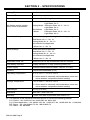
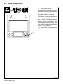
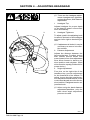
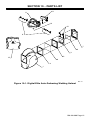
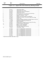
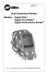
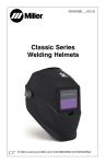
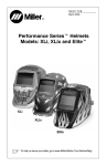
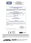
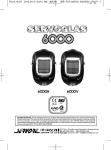
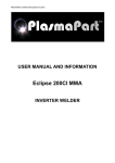
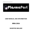
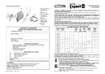
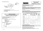
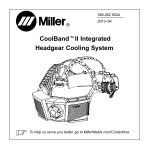
OM-234 388B
2007−08
®
Auto-Darkening Helmets
Model: Digital Elitet
To help us serve you better, go to www.MillerWelds.Com/HelmetReg/
TABLE OF CONTENTS
SECTION 1 − SAFETY PRECAUTIONS − READ BEFORE USING . . . . . . . . . . . . . . . . . . . . . . 1
1-1. Symbol Usage . . . . . . . . . . . . . . . . . . . . . . . . . . . . . . . . . . . . . . . . . . . . . . . . . . . . . . . . . . . . 1
1-2. Hazards . . . . . . . . . . . . . . . . . . . . . . . . . . . . . . . . . . . . . . . . . . . . . . . . . . . . . . . . . . . . . . . . . 1
SECTION 2 − SPECIFICATIONS . . . . . . . . . . . . . . . . . . . . . . . . . . . . . . . . . . . . . . . . . . . . . . . . . . . . 2
SECTION 3 − OPERATING INSTRUCTIONS . . . . . . . . . . . . . . . . . . . . . . . . . . . . . . . . . . . . . . . . . 3
3-1. Helmet Controls . . . . . . . . . . . . . . . . . . . . . . . . . . . . . . . . . . . . . . . . . . . . . . . . . . . . . . . . . . 3
3-2. On-Off Button And Low Battery Indicator . . . . . . . . . . . . . . . . . . . . . . . . . . . . . . . . . . . . . . 4
3-3. Mode Control . . . . . . . . . . . . . . . . . . . . . . . . . . . . . . . . . . . . . . . . . . . . . . . . . . . . . . . . . . . . . 5
3-4. Variable Shade Control . . . . . . . . . . . . . . . . . . . . . . . . . . . . . . . . . . . . . . . . . . . . . . . . . . . . 6
3-5. Sensitivity Control . . . . . . . . . . . . . . . . . . . . . . . . . . . . . . . . . . . . . . . . . . . . . . . . . . . . . . . . . 7
3-6. Lens Delay Control . . . . . . . . . . . . . . . . . . . . . . . . . . . . . . . . . . . . . . . . . . . . . . . . . . . . . . . . 8
3-7. Lens Adjustment Procedure . . . . . . . . . . . . . . . . . . . . . . . . . . . . . . . . . . . . . . . . . . . . . . . . 9
SECTION 4 − ADJUSTING HEADGEAR . . . . . . . . . . . . . . . . . . . . . . . . . . . . . . . . . . . . . . . . . . . . . 10
SECTION 5 − REPLACING THE LENS COVERS . . . . . . . . . . . . . . . . . . . . . . . . . . . . . . . . . . . . . 11
SECTION 6 − REPLACING THE BATTERY . . . . . . . . . . . . . . . . . . . . . . . . . . . . . . . . . . . . . . . . . . 12
SECTION 7 − INSTALLING OPTIONAL MAGNIFYING LENS . . . . . . . . . . . . . . . . . . . . . . . . . . 13
SECTION 8 − MAINTENANCE . . . . . . . . . . . . . . . . . . . . . . . . . . . . . . . . . . . . . . . . . . . . . . . . . . . . . 13
SECTION 9 − TROUBLESHOOTING . . . . . . . . . . . . . . . . . . . . . . . . . . . . . . . . . . . . . . . . . . . . . . . . 14
SECTION 10 − PARTS LIST . . . . . . . . . . . . . . . . . . . . . . . . . . . . . . . . . . . . . . . . . . . . . . . . . . . . . . . 15
SECTION 11 − LIMITED WARRANTY . . . . . . . . . . . . . . . . . . . . . . . . . . . . . . . . . . . . . . . . . . . . . . . 17
SECTION 1 − SAFETY PRECAUTIONS −
READ BEFORE USING
Protect yourself and others from injury — read and follow these precautions.
1-1. Symbol Usage
DANGER! − Indicates a hazardous
situation which, if not avoided, will
result in death or serious injury. The
possible hazards are shown in the
adjoining symbols or explained in
the text.
. Indicates special instructions.
Indicates a hazardous situation
which, if not avoided, could result in
death or serious injury. The possible
hazards are shown in the adjoining
symbols or explained in the text.
This group of symbols means Warning! Watch
Out! ELECTRIC SHOCK, MOVING PARTS,
and HOT PARTS hazards. Consult symbols
and related instructions below for necessary
actions to avoid the hazards.
NOTICE − Indicates statements not related to
personal injury.
1-2. Hazards
ARC RAYS can burn eyes and skin.
Arc rays from the welding process produce intense visible and invisible (ultraviolet and infrared) rays that can burn eyes and skin. Sparks fly off from the weld.
D Wear a welding helmet fitted with a proper shade of filter to protect your
face and eyes when welding or watching (see ANSI Z49.1 and Z87.1 listed
in Safety Standards). Refer to Shade and Sensitivity charts in Sections 3-4
and 3-5.
D Wear approved safety glasses with side shields under your helmet.
D Use protective screens or barriers to protect others from flash and glare;
warn others not to watch the arc.
D Wear protective clothing made from durable, flame-resistant material
(leather and wool) and foot protection.
WELDING HELMETS do not provide unlimited eye, ear and
face protection.
D Use impact resistant safety spectacles or goggles and ear protection at all
times when using this welding helmet.
D Do not use this helmet while working with or around explosives or
corrosive liquids.
D Do not weld in the overhead position while using this helmet.
D Inspect the auto-lens frequently. Immediately replace any scratched,
cracked, or pitted cover lenses or auto-lenses.
NOISE can damage hearing.
Noise from some processes or equipment can damage hearing.
D Wear approved ear protection if noise level is high.
OM-234 388 Page 1
SECTION 2 − SPECIFICATIONS
Viewing Field
97 x 60mm/3.81 x 2.62 in
Reaction Time
0.0000500sec (1/20,000)
Operating Modes
4 Modes: Weld, Cutting, Grind, X Mode
Available Shades
Weld Mode:
All shades provide continuous UV and IR protection.
Darkened State: No. 8 − No. 13
Light State: No. 3
Cutting Mode: Darkened State: No. 5 − No. 8
Light State: No. 3
Grind Mode: Light State: No. 3
X Mode:
Darkened State: No. 8 − No. 13
Light State: No. 3
Sensitivity Settings
Adjusts for varying ambient light and welding/cutting arc
Weld Mode: No. 0 − No. 10
Cutting Mode: No. 0 − No. 10
Grind Mode: Not Applicable
X Mode: No. 0 − No. 10
Delay Settings
Slows lens dark-to-light state
Weld Mode: No. 0 − No. 10
Cutting Mode: No. 0 − No. 10
Grind Mode: Not Applicable
X Mode: No. 0 − No. 10
Automatic Power Off
Shuts lens Off 15−20 minutes after last arc is struck
Low Battery Indicator
Display indicates 2−3 days remaining battery life
Power Supply
CR2450 Lithium Batteries (Miller Part No. 217 043)
Sensors
Independent/Redundant (Four)
Operating Temperature
14_F to 131_F / −10_C to +55_C
. When stored in extremely cold temperatures, warm helmet to ambient temperature before welding.
Storage Temperature
−4_F to 158_F / −20_C to +70_C
. When stored in extremely cold temperatures, warm helmet to ambient temperature before welding.
Total Weight
510.3 g (1 lb 2oz.)
Standards
ANSI Z87.1 and CSA/TUV
Warranty
2 years from date of purchase (see Section 11)
. The helmets in this manual are covered by one or more of the following patents:
U.S. Patent − No. 6,552,316, No. 6,483,090, No. 6,614,409
U.S. Patent Application − No. 29/223,100, No. 11/053,977, No. 10/565,858, No. 11/589,542
DE. Patent − No. 199 59 944 C2, No. 199 59 945 C2
FR. Patent − No. 9916004
OM-234 388 Page 2
SECTION 3 − OPERATING INSTRUCTIONS
3-1. Helmet Controls
1
On-Off Button (See Section
3-2)
Mode Control Button
(See Section 3-3)
Display Screen
Variable Shade Control
Buttons (See Section 3-4)
Sensitivity Control Buttons
(See Section 3-5)
Lens Delay Control Buttons
(See Section 3-6)
2
3
4
5
6
. The lens assembly saves the
shade, sensitivity, and delay
settings when the lens turns
off.
4
5
6
1
2
3
805 010
OM-234 388 Page 3
3-2. On-Off Button And Low Battery Indicator
1
On-Off Button
Press On-Off button to check if the
lens is working properly and to begin lens shade, sensitivity, and
delay adjustments.
When the On-Off button is pressed,
the lens should darken and return to
the clear state. Do not use the helmet if the lens does not function as
described. (See Section 9, Troubleshooting.)
2
Low Battery Indicator
The message “Low Battery” appears on the display screen when
2−3 days of battery life remains.
If battery power is low, replace with
CR2450 lithium batteries (2 required − Miller Part No. 217 043)
See Section 6.
1
2
805 010
OM-234 388 Page 4
3-3. Mode Control
1
Mode Control Button
Press button to select the mode appropriate for the work activity:
Weld Mode − used for most welding
applications. In this mode the lens
turns on when it optically senses a
welding arc. Adjust shade, sensitivity,
and delay settings as needed.
Cutting Mode − used for cutting applications. In this mode the lens turns
on when it optically senses a cutting
arc. Adjust shade, sensitivity, and
delay settings as needed.
Grind Mode − used for metal grinding
applications. In this mode the shade is
fixed shade No. 3. No lens adjustments are possible.
X Mode − used for outdoor or low current welding applications. In this mode
the lens turns on when it senses weld
current. Adjust shade, sensitivity, and
delay settings as needed.
. Nearby
welding may affect helmet operation when lens is in X
Mode. Stay at least 12 ft (3.7 m)
away from other welding activity.
1
805 010
OM-234 388 Page 5
3-4. Variable Shade Control
1
Shade Control Buttons
Use the shade control Down and
Up buttons to select the lens
shade in the darkened state. The
shade ranges for each mode are
as follows:
Weld − No. 8 − No. 13
Cutting − No. 5 − No. 8
Grind − No. 3 only
X Mode − No. 8 − No. 13
1
Start at the highest setting and adjust lighter to suit the application
and your personal preference.
Use the table below to select proper shade control setting based on
your welding process.
805 010
Application Welding
Arc Current in Amperes
Protective Shade No.
Stick Electrodes
Less than 40
40−80
80−175
175−300
300−500
9
10
11
12
13
MIG
Less than 100
100−175
175−300
300−500
10
11
12
13
Gas Tungsten Arc Welding
(TIG)
Less than 50
50−100
100−200
200−400
10
11
12
13
Air Carbon
Less than 500
500−700
12
13
Plasma Arc Cutting
60−150
150−250
250−400
11
12
13
Plasma Arc Welding
Less than 50
50−200
200−400
9
10
12
OM-234 388 Page 6
3-5. Sensitivity Control
1
Sensitivity Control Buttons
Use Sensitivity Control Low and Hi buttons
to make the lens more responsive to different light levels in various welding processes. Use a sensitivity setting of 5 for
most applications.
The sensitivity ranges for each mode are as
follows:
Weld, Cutting, X Modes − 0 − 10
Grind Mode − No sensitivity adjustment
It may be necessary to adjust helmet sensitivity to accommodate different lighting conditions or if lens is flashing On and Off. Adjust helmet sensitivity as follows:
1
. Adjust helmet sensitivity in lighting conditions helmet will be used in.
S
Press Sensitivity Low button to lower
setting to 0.
S
Face the helmet in the direction of use,
exposing it to the surrounding light conditions.
S
Press Sensitivity Hi button repeatedly
until the lens darkens, then press Low
button until lens clears. Helmet is ready
for use. Slight readjustment may be
necessary for certain applications or if
lens is flashing on and off.
805 010
Recommended Sensitivity Settings
Stick Electrode
Mid-Range
Short Circuiting (MIG)
Low/Mid-Range
Pulsed & Spray (MIG)
Mid-Range
Gas Tungsten Arc (TIG)
Mid/High-Range
Plasma Arc Cutting/Welding
Low/Mid-Range
Grinding
No sensitivity setting; use Grind mode
OM-234 388 Page 7
3-6. Lens Delay Control
1
Lens Delay Control
Use the Lens Delay Control Fast
and Slow buttons to adjust the time
for the lens to switch to the clear
state after welding or cutting.
The delay is particularly useful in
eliminating bright after-rays present in higher amperage applications where the molten puddle remains bright momentarily after
welding. Use the Lens Delay Control buttons to adjust delay from 0 to
10 (0.1 to 1.0 second).
. There is no lens delay adjustment in the Grind mode.
1
805 010
OM-234 388 Page 8
3-7. Lens Adjustment Procedure
. Lens assembly displays prior
settings when turned On. Retained settings are not shown
in example.
MODE
. In the Grind mode the lens is a
SHADE
fixed shade No. 3. No lens adjustments are possible.
SENSITIVITY
Adjusting Lens Assembly:
DELAY
MODE
WELD
SHADE
SENSITIVITY
S
Turn lens On. Display screen
appears.
S
Select mode (Weld, Cutting,
Grind, X-Mode)
S
Select Shade By Pressing
Down/Up Buttons.
S
Select Sensitivity By Pressing
Low/Hi Buttons.
S
Select Delay by Pressing
Fast/Slow Buttons.
S
Begin work.
DELAY
MODE
WELD
SHADE
12
SENSITIVITY
DELAY
MODE
WELD
SHADE
SENSITIVITY
12
6
DELAY
MODE
WELD
SHADE
SENSITIVITY
DELAY
12
6
5
805 010
OM-234 388 Page 9
SECTION 4 − ADJUSTING HEADGEAR
. There are four headgear adjust-
ments: headgear top, tightness,
angle adjustment, and distance
adjustment.
1
Headgear Top
Adjusts headgear for proper depth
on the head to ensure correct balance and stability.
1
3
2
Headgear Tightness
To adjust, push in the adjusting knob
located on the back of the headgear
and turn left or right to desired tightness.
. If adjustment is limited, it may be
necessary to remove the comfort cushion.
3
Distance Adjustment
Adjusts the distance between the
face and the lens. To adjust, loosen
both outside tension knobs and
press inward to free from adjustment
slots. Move forward or back to desired position and retighten. (Both
sides must be equally positioned for
proper vision.)
4
2
4
Angle Adjustment
Four pins on the right side of the
headband top provide adjustment
for the forward tilt of the helmet. To
adjust, loosen the right outside tension adjustment knob then lift on the
control arm tab and move it to the desired position. Retighten tension adjustment knob.
. When using the back distance
adjustment positions, only the
back three angle adjustment
pins can be used.
804 118
OM-234 388 Page 10
SECTION 5 − REPLACING THE LENS COVERS
Be sure wide edge
of gasket faces
helmet shell.
Be sure flat side
of gasket faces
helmet shell.
6
5
4
3
2
1
Ref. 805 012
!
Never use the autodarkening lens without the inside and outside lens covers properly installed. Welding
spatter will damage
the
auto-darkening
lens and void the
warranty.
1
Front Lens Gasket
2
Outside Lens Cover
3
Lens Assembly Gasket
4
Lens Assembly
5
Inside Lens Cover
6
Lens Frame
Remove the lens assembly
to remove either lens cover.
To remove the lens assembly, push down on the helmet
bottom retaining arms and
push the retaining clips toward the outside of the helmet. Lift up on the assembly
and pull free of the helmet.
Outside Lens Cover
Remove the outside lens
cover by pushing cover into
the helmet. Remove the rubber lens gasket and install on
the new lens cover. Reinstall
the lens assembly.
. Be sure the flat side of
lens cover gasket faces
the helmet shell.
Inside Lens Cover
To replace the inside lens
cover, remove the lens assembly from the lens frame
by pushing up on the top two
retaining tabs while gently
pushing the lens free.
Remove the lens cover by
sliding it out of either side.
Replace with the new cover
lens and reinstall the assembly in the helmet.
OM-234 388 Page 11
SECTION 6 − REPLACING THE BATTERY
To replace the batteries, remove the auto-darkening lens
assembly (see Section 5).
1
After removing the lens assembly, slide the battery holding trays out and remove the
old batteries.
1
+
+
Be sure Positive
(+) side of battery
faces up.
Battery Tray
Replace with CR2450 lithium
type batteries (2 required) or
equivalent (Miller Part No.
217043).
. Be sure Positive (+) side
of the battery faces up (toward inside of helmet).
Reinstall the battery trays. To
test, press the On button. The
display screen should turn on.
Reinstall the lens assembly.
. Left and right battery trays
are not interchangeable.
The auto−darkening helmet will not work if battery
trays are installed on the
wrong sides.
805 010
OM-234 388 Page 12
SECTION 7 − INSTALLING OPTIONAL MAGNIFYING LENS
1
Optional Magnifying Lens
Starting at the top, slide magnifying
lens into the helmet retaining brackets. Align the magnifying lens with
the auto-darkening lens assembly.
1
Reverse procedure to remove
magnifying lens.
. To prevent lens fogging, install
flat side of magnifying lens toward auto-darkening lens.
805 011
SECTION 8 − MAINTENANCE
NOTICE − Never use solvents or abrasive cleaning detergents.
NOTICE − Do not immerse the lens assembly in water.
The helmet requires little maintenance. However, for best performance clean
after each use. Using a soft cloth dampened with a mild soap and water solution,
wipe the cover lenses clean. Allow to air dry. Occasionally, the filter lens and
sensors should be cleaned by gently wiping with a soft, dry cloth.
OM-234 388 Page 13
SECTION 9 − TROUBLESHOOTING
Trouble
Remedy
Auto lens not ON – autolens does not darken momentarily when the On
button is pressed.
Check batteries and verify they are in good condition and installed
properly.
Not switching – auto-lens
stays light and does not
darken when welding or
cutting.
Stop welding or cutting immediately: Make sure the lens is turned
On.
Check battery surfaces and contacts, and clean if necessary.
Check battery for proper contact and gently adjust contact points
if necessary. This is particularly important if the helmet has been
dropped. Verify left and right battery trays are installed on the
correct sides.
If power is On, check the mode settings. Also review sensitivity
recommendations and adjust sensitivity if possible.
Clean lens cover and sensors of any obstructions. Make sure the
sensors are facing the arc; angles of 45_ or more may not allow
the arc light to reach the sensors.
Not Switching – auto-lens
stays dark after the arc is
extinguished, or the autolens stays dark when no
arc is present.
Reduce Sensitivity setting (see Section 3-5). In extreme light conditions, it may be necessary to reduce the surrounding light levels.
Sections of the auto-lens
are not going dark, distinct
lines separate the light and
dark areas.
Stop welding or cutting immediately: The auto-lens may be
cracked which can be caused by the impact of dropping the helmet.
Switching or Flickering –
the auto-lens darkens then
lightens while the welding
or cutting arc is present.
Review the sensitivity setting recommendations and increase the
sensitivity if possible. Be sure the arc sensors are not being
blocked from direct access to the arc light.
Inconsistent or lighter
auto-lens shading in the
dark-state, noticeable on
the outside edges and corners.
Referred to as an angle of view effect, auto-darkening lenses
have an optimum viewing angle.
. If the lens remains dark, press the On-Off button to return lens
to the clear state.
Weld spatter on the auto lens may also cause cracking. (The lens
may need to be replaced; most cracked lenses are not covered by
warranty).
Check the lens cover for dirt and spatter that may be blocking the
arc sensors. Increasing Lens Delay 0.1 − 0.3 second may also
reduce switching.
The optimum viewing angle is perpendicular or 90_ to the surface
of the auto-lens. When that angle of view varies in the dark-state,
welders may notice slightly lighter areas at the outside edges and
the corners of the lens. This is normal and does not represent any
health or safety hazard.
This effect may also be more noticeable in applications where
magnifying lenses are used.
OM-234 388 Page 14
SECTION 10 − PARTS LIST
11
8
10
12
9
Miller
7
2
3
5
13
6
4
1
804 111
Figure 10-1. Digital Elite Auto-Darkening Welding Helmet
OM-234 388 Page 15
Item
No.
Part
No.
Description
Quantity
Figure 10-1. Digital Elite Auto-Darkening Welding Helmet
1 . . . . . . . . . . . . 216 331 . . . . . . . . Helmet Shell, Black . . . . . . . . . . . . . . . . . . . . . . . . . . . . . .
1 . . . . . . . . . . . . 227 189 . . . . . . . . Helmet Shell, The Joker . . . . . . . . . . . . . . . . . . . . . . . . . . .
1 . . . . . . . . . . . . 234 066 . . . . . . . . Helmet Shell, Stars And Stripes II . . . . . . . . . . . . . . . . . . .
1 . . . . . . . . . . . . 223 454 . . . . . . . . Helmet Shell, Inferno . . . . . . . . . . . . . . . . . . . . . . . . . . . . .
2 . . . . . . . . . . . . 216 327 . . . . . . . . Inside Lens Cover (4-1/4 X 2-1/2) (5 Per Pkg.) . . . . . . . .
3 . . . . . . . . . . . . 234 760 . . . . . . . . Auto-darkening Lens Assembly . . . . . . . . . . . . . . . . . . . .
4 . . . . . . . . . . . . 216 337 . . . . . . . . Gasket, Front Lens − Cover . . . . . . . . . . . . . . . . . . . . . . .
5 . . . . . . . . . . . . 234 758 . . . . . . . . Gasket, Auto-Darkening Lens Assembly . . . . . . . . . . . . .
6 . . . . . . . . . . . . 216 326 . . . . . . . . Outside Lens Cover (4-11/16 X 5-5/8) (5 Per Pkg.) . . . .
7 . . . . . . . . . . . . 234 759 . . . . . . . . Frame, Lens . . . . . . . . . . . . . . . . . . . . . . . . . . . . . . . . . . . .
8 . . . . . . . . . . . . 770 246 . . . . . . . . Ratchet Headgear Assembly (Includes Items 9 And 10)
9 . . . . . . . . . . . . 770 248* . . . . . . . Adjustment Angle/Stop Hardware Kit . . . . . . . . . . . . . . . .
10 . . . . . . . . . . . 770 249 . . . . . . . . Fabric Headband . . . . . . . . . . . . . . . . . . . . . . . . . . . . . . . .
. . . . . . . . . . . . . . 079 975 . . . . . . . . Replacement O-rings For Kit 770 248 (5 Per Pkg.) . . . .
11 . . . . . . . . . . . 216 336 . . . . . . . . Comfort Cushion, Foam Rubber . . . . . . . . . . . . . . . . . . . .
12 . . . . . . . . . . . 216 339 . . . . . . . . Battery Tray Kit (Left/Right) . . . . . . . . . . . . . . . . . . . . . . . .
. . . . . . . . . . . . . . 217 043 . . . . . . . . Battery, Lithium (CR2450) . . . . . . . . . . . . . . . . . . . . . . . . .
. . . . . . . . . . . . . . 222 003 . . . . . . . . Hard Hat Adapters (Not Shown) . . . . . . . . . . . . . . . . . . . .
13 . . . . . . . . . . . 770 250 . . . . . . . . Helmet Bag − Miller . . . . . . . . . . . . . . . . . . . . . . . . . . . . . .
. . . . . . . . . . . . . . 212 235 . . . . . . . . Lens, 0.75 Magnification (Not Shown) . . . . . . . . . . . . . . .
. . . . . . . . . . . . . . 212 236 . . . . . . . . Lens, 1.00 Magnification (Not Shown) . . . . . . . . . . . . . . .
. . . . . . . . . . . . . . 212 237 . . . . . . . . Lens, 1.25 Magnification (Not Shown) . . . . . . . . . . . . . . .
. . . . . . . . . . . . . . 212 238 . . . . . . . . Lens, 1.50 Magnification (Not Shown) . . . . . . . . . . . . . . .
. . . . . . . . . . . . . . 212 239 . . . . . . . . Lens, 1.75 Magnification (Not Shown) . . . . . . . . . . . . . . .
. . . . . . . . . . . . . . 212 240 . . . . . . . . Lens, 2.00 Magnification (Not Shown) . . . . . . . . . . . . . . .
. . . . . . . . . . . . . . 212 241 . . . . . . . . Lens, 2.25 Magnification (Not Shown) . . . . . . . . . . . . . . .
. . . . . . . . . . . . . . 212 242 . . . . . . . . Lens, 2.50 Magnification (Not Shown) . . . . . . . . . . . . . . .
* Adjustment Hardware Kit With O-rings.
OM-234 388 Page 16
1
1
1
1
1
1
1
1
1
1
1
1
1
1
1
1
2
1
1
1
1
1
1
1
1
1
1
SECTION 11 − LIMITED WARRANTY
Effective January 1, 2007
LIMITED WARRANTY – Subject to the terms and conditions below. Miller
Electric Mfg. Co., Appleton, Wisconsin, warrants to its original retail purchaser that the new Miller equipment sold after the effective date of this
limited warranty is free of defects in material and workmanship at the time
it is shipped by Miller. THIS WARRANTY IS EXPRESSLY IN LIEU OF ALL
OTHER WARRANTIES, EXPRESS OR IMPLIED, INCLUDING THE
WARRANTIES OR MERCHANTABILITY AND FITNESS.
Miller Elite Series auto-darkening lens helmets are warranted for 2 years
from the date of purchase. Proof of purchase is required for warranty
transactions so it is imperative that a copy of the original invoice or sales
receipt be retained.
For warranty transactions, contact your Miller Distributor.
OM-234 388 Page 17
Visit our website at
www.MillerWelds.com
®
Miller Electric Mfg. Co.
An Illinois Tool Works Company
1635 West Spencer Street
Appleton, WI 54914 USA
PRINTED IN USA
© 2007 Miller Electric Mfg. Co.