1
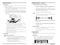
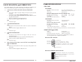
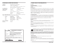
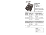
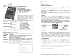
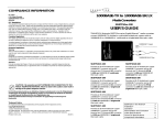
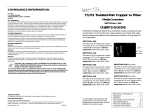
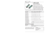
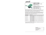
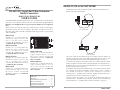
RS485-CF-0X in the NETWORK
The RS485-CF-0x can be used to install a fiber network extension between
RS-485 or RS-422 network nodes.
RS-485/422 Serial-Port Fiber Extension
Media Converters
RS485-CF-01, RS485-CF-02
USER’S GUIDE
The TRANSITION Networks RS485-CF-0x series serial-port fiber extension Media
Converters extend distances between RS-485 or RS-482 nodes for up to two (2)
kilometers over multimode fiber or up to twenty (20) kilometers over singlemode
fiber.
RS485-CF-0x series Media Converters allow RS-485 two-wire half-duplex
operation, RS-485 four-wire full-duplex operation, and RS-422 four-wire
operation, with switch-selectable termination and biasing resistors, at speeds from
1 Kb/s to 500 Kb/s.
RS-485/422 CABLE
RS485-CF-01(SM)
Provides one (1) terminal block RS485/RS-422 copper connector and
one (1) set of RX (receive) and TX
(transmit) ST 100BASE-FX connectors
to singlemode fiber @ 1300 nM.
RS485-CF-01(SC)
Provides one (1) terminal block RS485/RS-422 copper connector and
one (1) set of RX (receive) and TX
(transmit) SC 100BASE-FX connectors
to multimode fiber @ 850 nM.
RS485-CF-02
Provides one (1) DB-9 RS-485/RS-422
copper connector and one (1) set of
RX (receive) and TX (transmit) ST
100BASE-FX connectors to multimode
fiber @ 850 nM.
DB-9
Fiber
Provides one (1) terminal block RS485/RS-422 copper connector and
one (1) set of RX (receive) and TX
(transmit) ST 100BASE-FX connectors
to multimode fiber @ 850 nM.
RS485/422 to Fiber
Media Converter
RS485-CF-01
RS485-CF-02(SM)
Provides one (1) DB-9 RS-485/RS-422
copper connector and one (1) set of
RX (receive) and TX (transmit) ST
100BASE-FX connectors to singlemode
fiber @ 1300 nM.
RS-485/422 CABLE
One slide switch on the RS485-CF-0x series Media Converter allows site
selection of RS-485 2-wire (half-duplex) operation, RS-485 4-wire (fullduplex) operation, or RS-422 4-wire (full-duplex) operation (see page 3).
RS485-CF-02(SC)
A second slide switch on the RS485-CF-0x series Media Converter allows
echo prevention in two-wire mode or transmission only on "transmit/receive (B) RS-485 2wire, transmit - RS-422 and transmit/receive + (A) RS-485 2wire,
transmit + RS-422" pair (see page 3).
Provides one (1) DB-9 RS-485/RS-422
copper connector and one (1) set of
RX (receive) and TX (transmit) SC
100BASE-FX connectors to multimode
fiber @ 850 nM.
A 4-position dip switch on the RS485-CF-0x series Media Converter allows
site selection of 130 ohm terminator insertion on the "receive – RS485 4
wire, RS422 and receive + RS485 4 wire, RS422" pair or on the
"transmit/receive - (B) RS485 2wire, transmit - RS422 and transmit/receive +
(A) RS485 2wire, transmit + RS422" pair (see page 3.).
RS485-CF-0x in the Network . . . . . .2
Installation . . . . . . . . . . . . . . . . . . . .3
Operation . . . . . . . . . . . . . . . . . . . . .4
Fault Isolation and Correction . . . . .5
Cable Specifications . . . . . . . . . . . . .6
Technical Specifications . . . . . . . . . .7
Compliance Information . . . . . . . . . .8
The dip switch also allows site selection of 1K ohm pull down on
"transmit/receive - (B) RS485 2wire, transmit - RS422" or of 1K ohm pull up
on "transmit/receive + (A) RS485 2wire, transmit + RS422” (see page 3).
2
RS485-CF-0x
INSTALLATION
INSTALLATION -- Continued
Set Switches
COPPER /TERMINAL BLOCK CONNECTOR
Use small flatblade screwdriver or similar device to set recessed switches
according to site installation.
1.
Locate or build TIA/EIA-574-compliant terminal block cables
configured as shown on page 6 and with straight-through cable.
1.
Set the 2-wire /4-wire slide switch to the 4-wire setting to enable the
"receive – RS485 4 wire, RS422 and receive + RS485 4 wire, RS422"
pair for RS422 4 wire full duplex operation.
2.
2.
Set the RS-485/RS-422 slide switch to the RS-485 position to prevent
echo in two-wire mode. Set the RS-485/RS-422 slide switch to the RS422 to allow transmit only on "transmit/receive - (B) RS-485 2wire,
transmit - RS-422 and transmit/receive + (A) RS-485 2wire, transmit +
RS-422" pair.
Using a small flatblade screwdriver or a similar device, release each
terminal block installation location as necessary. Refer to the
diagram on page 6, connect the wires at one end of cable to the
Media Converter terminal block connector.
3.
Connect the other end of the cable to the node device.
FIBER
1.
DOWN=ON Inserts 130 resistor on "receive"*
DOWN=ON Inserts 130 resistor on "transmit"**
DOWN=ON Enables 1K "pull-down"***
DOWN=ON Enables 1K "pull-up"****
RS-485
1
2-wire
2
3
In
X
t
-F
pu
TX
4
-O
Connect the male TX and RX cable connectors at the other end of
the cable to the RX and TX connectors of the IEEE 802.3™
compliant fiber device.
C
B
Position 1 ON inserts 130 ohm terminator on the "receive – RS485
4 wire, RS422 and receive + RS485 4 wire, RS422" pair.
**
Position 2 ON inserts 130 ohm terminator on the "transmit/receive (B) RS485 2wire, transmit - RS422 and transmit/receive + (A) RS485
2wire, transmit + RS422" pair.
Connect to Power
*** Position 3 ON enables 1K ohm pull down on "transmit/receive - (B)
RS485 2wire, transmit - RS422".
**** Position 4 ON enables 1K ohm pull up on "transmit/receive + (A)
RS485 2wire, transmit + RS422
1.
Install the power adapter cord at the back of the Media Converter.
2.
Connect the power adapter plug to AC power.
3.
Verify that the Media Converter is powered by observing the
illuminated LED(s).
OPERATION
After installation, the Media Converter should function without operator
intervention.
Install Cable
Status LEDs:
COPPER /DB-9 CONNECTOR
Use the status LEDs to monitor Media Converter operation in the network.
NOTE: Shielded cables are required on the DB-9 for EMC compliance.
3.
RX
3.
D
00
*
2.
RX
Connect the male TX and RX cable connectors at one end of the
cable to the TX and RX female connectors, respectively, on the
Media Converter.
Config
Switches
1234
Refer to drawing and to notes below for setting 4-position DIP switch.
1.
TX
2.
9V
-1
E
MDI-X
TX
4
4-wire
MDI
3.
RS-422
Locate or build TIA/EIA-574-compliant fiber cable with male twostranded TX to RX connectors at both ends.
Locate or build TIA/EIA-574-DB-9 compliant cables configured as
shown on page 6, with a male DB-9 connector at one end of
cable and with a straight-through cable.
RXF
Flashing LED indicates data reception on the fiber link.
RXC
Flashing LED indicates data reception on the copper link.
P(o)W(e)R Steady LED indicates connection to external power.
Connect the male DB-9 connector at one end of cable to the
Media Converter female DB-9 connector.
RXF
RXC
Connect the other end of cable to the node device.
PWR
Fiber
3
4
DB-9
RS485-CF-0x
CABLE SPECIFICATIONS
FAULT ISOLATION and CORRECTION
If the Media Converter fails, isolate and correct the failure by determining the
answers to the following questions and then taking the indicated action:
1.
Fiber Cable
MULTIMODE
Is the P(o)w(e)r LED on the Media Converter illuminated?
NO
•
•
•
•
Fiber Optic Cable Recommended:
Optional:
Wavelength:
Is the power adapter the proper voltage and cycle frequency for the
AC outlet?
NOTE: Refer to the “Power Supply Requirements” on page 7.
Is the power adapter properly installed in the Media Converter and in
the grounded AC outlet?
Does the grounded AC outlet provide power?
Contact Technical Support at (800) 260-1312.
RS485-CF-01, RS485-CF-01(SC), RS485-CF-02, RS485-CF-02(SC):
Fiber Optic Transmitter Power:
min: -16.0 dBm
max: -10.0 dBm
Fiber Optic Receiver Sensitivity:
min: -32.0 dBm
max: -7.2 dBm
Link Budget:
16.0 dB
Typical Maximum Cable Distance**:
2 kilometers
SINGLEMODE
YES
•
2.
Proceed to step 2.
Is the RXF LED illuminated?
NO
•
•
Disconnect and reconnect the fiber cable to restart the initialization
process.
Contact Technical Support: (800) 260-1312.
YES
•
3.
•
•
Fiber Optic Cable Recommended:
Wavelength:
9 µm singlemode fiber
1300 nanometers
RS485-CF-01(SM), RS485-CF-02(SM)
Fiber Optic Transmitter Power:
Fiber Optic Receiver Sensitivity:
Link Budget:
Typical Maximum Cable Distance**:
min: -23.0 dBm
min: -34.0 dBm
11.0 dB
20 kilometers
max: -14.0 dBm
max: -14.0 dBm
**Actual distance dependent upon physical characteristics of network installation.
RS-485/422 Copper Cable
Proceed to step 3.
Gauge
24 to 22 AWG
Attenuation
20 dB/1000’ @ 10 MHz
Differential Characteristic Impedance
100 Ω ±10% @ 10 MHz
Maximum Cable Distance varies by baud rate: 4000ft[1220M] at <90kbaud
decreasing logarithmically to 300ft[92M] at 500kbaud).
Is the RXC LED illuminated?
NO
•
62.5 / 125 µm multimode fiber
100/140, 85/125, 50/125 µm mm fiber
850 nanometers
Disconnect and reconnect the copper cable to restart the
initialization process.
Restart the terminal device(s) to restart the initialization process.
Contact Technical Support: (800) 260-1312.
RS-485/422 DB-9 SIGNALS
YES
•
4.
Proceed to step 4.
Not Used
Not Used
Not Used
Not Used
Does the data fail to move across the link, even though both
LEDs are illuminated?
YES
•
•
Check the RS-485/RS-422 cables for proper configuration and
connection.
Contact Technical Support at (800) 260-1312.
9
8
7
6
5 Signal Ground
4 Receive (-) (B) RS-485 4-wire, (-) RS-422
3 Receive (+) (A) RS-485 4-wire, (+) RS-422
2 Transmit/Receive (+) (A) RS-485 2 or 4-wire, (+) RS-422
1 Transmit/Receive (-) (B) RS-485 2 or 4-wire, (-) RS-422
Protective Ground
RS-485/422 TERMINAL BLOCK SIGNALS
6
5
4
3
2
1
5
6
Transmit/Receive (-) (B) RS-485 2-wire, (-) RS-422 Transmit
Transmit/Receive (+) (A) RS-485 2-wire, (+) RS-422 Transmit
Receive (+) RS-485 4-wire, RS-422
Receive (-) RS-485 4-wire, RS-422
Ground
Ground
RS485-CF-0x
TECHNICAL SPECIFICATIONS
COMPLIANCE INFORMATION
Standards
ANSI/TIA/EIA-485-A, IEEE 802.3™
Data Rate
1000 baud to 500,000 baud.
UL Listed
C-UL Listed (Canada)
CISPR22/EN55022 Class A + EN55204
CE Mark
(No rate setting is required. The Media Converter
adjusts automatically to the baud rate.)
Case Dimensions
4.7" x 3.0" x 1.8"
(119mm x 76mm x 46mm)
Shipping Weight
3 pounds
(1.4 kilograms)
Environment
Temperature:
0-50°C (32° to 122° F )
This equipment has been tested and found to comply with the limits for a class A digital
device, pursuant to part 15 of the FCC rules. These limits are designed to provide reasonable
protection against harmful interference when the equipment is operated in a commercial
environment. This equipment generates, uses, and can radiate radio frequency energy and, if
not installed and used in accordance with the instruction manual, may cause harmful
interference to radio communications. Operation of this equipment in a residential area is
likely to cause harmful interference, in which case the user will be required to correct the
interference at the user's own expense.
Storage Temperature: -20 to 85°C
Humidity
10-90%, non condensing
Altitude
0-10,000 feet
Power Supply Requirements Replace the power supply only with the equivalent input
rating (see below) and output rating (regulated 9VDC at 500 mA).
TN PN
Requirement
Location
3525
3525
3518
3514
3348
240 volts, 50 hertz
230 volts, 50 hertz
120 volts, 60 hertz
100 volts, 50-60 hertz
240 volts, 50 hertz
United Kingdom
Europe
USA/Canada/Mexico
Japan
Australia
Power Consumption
2.2 Watts
Warranty
Lifetime
FCC Regulations
Canadian Regulations
This digital apparatus does not exceed the Class A limits for radio noise for digital apparatus
set out on the radio interference regulations of the Canadian Department of Communications.
Le présent appareil numérique n'émet pas de bruits radioélectriques dépassant les limites
applicables aux appareils numériques de la class A prescrites dans le Règlement sur le
brouillage radioélectrique édicté par le ministère des Communications du Canada.
European Regulations
Warning
This is a Class A product. In a domestic environment this product may cause radio
interference in which case the user may be required to take adequate measures.
Achtung !
Dieses ist ein Gerät der Funkstörgrenzwertklasse A. In Wohnbereichen können bei Betrieb
dieses Gerätes Rundfunkstörungen auftreten, in weichen Fällen der Benutzer für
entsprechende Gegenmaßnahmen werantwortlich ist.
Attention !
Ceci est un produit de Classe A. Dans un environment domestique, ce produit risque de créer
des interférences radioélectriques, il appartiendra alors à l'utilsateur de prende les measures
spécifiques appropriées.
CAUTION: RJ connectors are NOT INTENDED FOR CONNECTION TO THE
PUBLIC TELEPHONE NETWORK. Failure to observe this caution could result in
damage to the public telephone network.
DECLARATION OF CONFORMITY
Der Anschluss dieses Gerätes an ein öffentlickes Telekommunikationsnetz in den EGMitgliedstaaten verstösst gegen die jeweligen einzelstaatlichen Gesetze zur Anwendung der
Richtlinie 91/263/EWG zur Angleichung der Rechtsvorschriften der Mitgliedstaaten über
Telekommunikationsendeinrichtungen einschliesslich der gegenseitigen Anerkennung ihrer
Konformität.
Name of Mfg:
Transition Networks
6475 City West Parkway, Minneapolis MN 55344 USA
Model:
RS485-CF-0x Series Serial-Port Extension Media Converters
Part Number(s):
RS485-CF-01, RS485-CF-01(SM), RS485-CF-01(SC),
RS485-CF-02, RS485-CF-02(SM), RS485-CF-02(SC)
Regulation:
EMC Directive 89/336/EEC
Purpose: To declare that the RS485-CF-0x to which this declaration refers is in
conformity with the following standards.
EMC-CISPR 22: 1985 Class A; EN 55022: 1988 Class A; EN 50082-1:1992;
EN 60950 A4:1997; IEC 801.2, IEC 801.3, and IEC 801.4; IEC 950
Trademark Notice
All registered trademarks and trademarks are the property of their respective owners.
Copyright Restrictions
© 2000, 2002, 2003 TRANSITION Networks.
All rights reserved. No part of this work may be reproduced or used in any form or by any
means - graphic, electronic, or mechanical - without written permission from TRANSITION
Networks.
Printed in the U.S.A.
33158.D
I, the undersigned, hereby declare that the equipment specified above conforms to the above
Directive(s) and Standard(s).
_April 11, 2000_____
Stephen Anderson, Vice-President of Engineering
Date
7
8
RS485-CF-0x