1
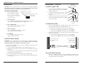
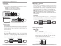
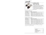
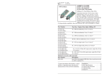
USER’S GUIDE
E-100BTX-FX-N-01
E-100BTX-FX-NLP-01
PCI Media Converter
• Ethernet
• Copper to Fiber
-NLP-01 • 100Base-TX to 100Base-FX
Transition Networks E-100BTX-FX-N-01
and E-100BTX-FX-NLP-01 series media
-N-01
converters connect 100Base-TX
twisted-pair copper cables to 100BaseFX fiber optic cables and are PCI
(Peripheral Component Interconnect)
powered. These converters are designed to install directly inside a PC workstation
or file server and mount on any slot on a standard PCI. No additional power
supply is needed since the power is drawn directly from the PCI slot. Two LEDs
allow for network monitoring.
The E-100BTX-FX-N-01 series media converter is 4.8 in. (121 mm) wide while the
E-100BTX-FX-NLP-01 series media converter is 3.2 in (80 mm) wide.
Part Number
E-100BTX-FX-N-01
E-100BTX-FX-NLP-01
Port One - Copper
100Base-TX
RJ-45
100 m (328 ft)*
Port Two - Duplex Fiber-Optic
100Base-FX
ST, 1300 nm multimode
2 km (1.2 miles)*
E-100BTX-FX-N-01(SC)
E-100BTX-FX-NLP-01(SC)
RJ-45
100 m (328 ft)*
SC, 1300 nm multimode
2 km (1.2 miles)*
E-100BTX-FX-N-01(SM)
E-100BTX-FX-NLP-01(SM)
RJ-45
100 m (328 ft)*
SC, 1310 nm single mode
20 km (12.4 miles)*
* Typical maximum cable distance. Actual distance is dependent upon the
physical characteristics of the network installation.
Installation . . . . . . . . . . . . . . . . . .2
Operation . . . . . . . . . . . . . . . . . . .4
Cable Specifications . . . . . . . . . . .5
Technical Specifications . . . . . . . .6
Troubleshooting . . . . . . . . . . . . . .7
Compliance Information . . . . . . . .8
E-100BTX-FX-N-01 / E-100BTX-FX-NLP-01
Installation
Installation -- Continued
CAUTION: Wear a grounding device and observe electrostatic discharge
precautions when setting the 4-position switch. Failure to observe this caution
could result in damage to, and failure of, the media converter.
Set the 4-Position Switch
•
The 4-position switch is
located on the circuit board.
•
Use a small flat-blade
screwdriver to set the
recessed switches.
1.
2.
Auto-Negotiation (up = enable)
Pause (up = enable)
Link Pass-Through (up = enable)
Far End Fault
(up = enable)
Install the Copper Cable
1.
Use the enclosed 100Base-TX compliant
copper cables with male, RJ-45 connectors
installed at both ends.
2.
Connect the RJ-45 connector at one end of
the cable to the RJ-45 port on the media
converter.
3.
Connect the RJ-45 connector at the other end
of the cable to the RJ-45 port on the network
interface card (NIC).
1 2 3 4
Auto-Negotiation
up
Enable Auto-Negotiation for the copper link (see page 4).
down Disable Auto-Negotiation for the copper link.
Pause Control Frame
up
Enable the pause feature (see page 5).
down Disable the pause feature.
3.
Link Pass-Through
up
Enable Link Pass-Through (see page 4).
down Disable Link Pass-Through.
4.
Far-End Fault
up
Enable Far-End Fault (see page 5).
down Disable Far-End Fault.
Install the Fiber Cable
Locate or build 100Base-FX compliant fiber cable with male, twostranded TX to RX connectors installed at both ends.
2.
Connect the fiber cables to the media converter as described:
• Connect the male TX cable connector to the female TX port.
• Connect the male RX cable connector to the female RX port.
3.
Connect the fiber cables to the other device (another media converter,
hub, etc.) as described:
• Connect the male TX cable connector to the female RX port.
• Connect the male RX cable connector to the female TX port.
Connect the fiber cable
to the media converter
as shown.
CAUTION: Wear a grounding device and observe electrostatic discharge
precautions when installing the slide-in-module. Failure to observe this caution
could result in damage to, and failure of, the media converter.
2
Tech Support: 1-800-260-1312 International: 00-1-952-941-7600 (24 hours)
RJ-45 port
on the media
converter
1.
Install the Slide-in-Module
To install the E-100BTX-FX-N-01 or the E-100BTX-FX-NLP-01 media
converter slide-in-module:
1. Locate an empty installation slot on the PC workstation or file server.
2. Remove the screws that secure the cover over the installation slot. Retain
the screws.
3. Carefully slide the slide-in-module into the installation slot, aligning the
module with the installation guides.
4. Ensure that the module is firmly seated in the installation slot.
5. Use the screws from step 2 to secure the module to the workstation or file
server housing.
RJ-45 port
on the network
interface card (NIC)
Connect the fiber cable
to the other device
(media converter,
hub, etc.) as shown
RX
RX
TX
TX
Power the Media Converter
Both the E-100BTX-FX-N-01 and the E-100BTX-FX-NLP-01 media
converters are powered by the PCI (Peripheral Component Interconnect)
edge connector on the circuit board.
[email protected] -- Click the “Transition Now” link for a live Web chat.
3
E-100BTX-FX-N-01 / E-100BTX-FX-NLP-01
Operation -- Continued
Operation
Pause Control Frame
LED Indicators
Use the status LEDs to monitor the media converter operation in the network.
FX LED on = The fiber link has been established.
TX LED on = The copper link has been established.
(Both LEDs off = No power to the media converter.)
FX
NOTE: Enable the pause feature if it is present on ALL network devices
attached to the media converter(s). Otherwise, disable the pause feature.
TX
E-100BTX-FX-NLP-01
TX 100Base-FX
RX
The pause feature is used to temporarily suspend data transmission in order to
relieve buffer congestion. If a media converter needs some time to clear
network congestion, it will send a pause signal to the media converter at the
other end, which will wait a predetermined amount of time before retransmitting the data. This feature reduces data bottlenecks, allows for a more
efficient use of the network devices, and prevents the loss of valuable data.
NOTE: Disable the pause feature in networks with E-911, VoIP, or other timecritical applications.
LINK
FX
TX
100Base-TX
Far-End Fault
FX
When a fault occurs on an incoming fiber link (1), the media converter
transmits a Far-End Fault signal on the outgoing fiber link (2). In addition the
Far-End Fault signal also activates the Link Pass-Through feature, which, in
turn, disables the link on the copper portion of the network (3) and (4).
TX
E-100BTX-FX-N-01
TX 100Base-FX
RX
LINK
FX
TX
original fault
on the fiber link
100Base-TX
Near-End
Device
4
Media
Converter A
media converter A
disables the copper link
Product Features
1
Media
Converter B
2
Far-End Fault
signal is sent
3
Far-End
Device
media converter B
disables the copper link
Auto-Negotiation
The Auto-Negotiation feature allows the media converter to automatically
configure itself to achieve the best possible mode of operation over a link.
This feature allows quick and easy installation because the optimal link is
established automatically. No user intervention is required to determine the
best mode of operation.
The Link Pass-Through feature allows the media converter to monitor both the
fiber and copper RX (receive) ports for loss of signal. In the event of a loss of
an RX signal (1), the media converter will automatically disable the TX
(transmit) signal (2), thus, “passing through” the link loss (3). The far-end
device is automatically notified of the link loss (4), which prevents the loss of
valuable data unknowingly transmitted over an invalid link.
media converter A
disables the fiber TX link
1
Media
Converter A
original fault
on the copper link
4
Copper Cable
Category 5:
Gauge:
24 to 22 AWG
Attenuation: 22.0 dB /100m @ 100 MHz
Link Pass-Through
Near-End
Device
Cable Specifications
2
media converter B
loses the fiber RX link
3
• Straight-through (MDI) twisted-pair cable must be used.
• Shielded (STP) or unshielded (UTP) twisted-pair cable may be used.
• Pins 1&2 and 3&6 are the two active pairs in an Ethernet network .
• RJ-45 Pin-out: Pin 1 = TD+, Pin 2 = TD-, Pin 3 = RD+, Pin 6 = RD• Use only dedicated wire pairs for the active pins:
(e.g., blue/white & white/blue, orange/white & white/orange, etc.)
• Do not use flat or silver satin wire.
Straight-Through Cable
Media
Converter B
4
Far-End
Device
media converter B
disables the copper link
Tech Support: 1-800-260-1312 International: 00-1-952-941-7600 (24 hours)
Twisted Pair #1
1
2
1
2
Twisted Pair #2
3
6
3
6
[email protected] -- Click the “Transition Now” link for a live Web chat.
5
E-100BTX-FX-N-01 / E-100BTX-FX-NLP-01
Cable Specifications -- Continued
The physical characteristics must meet or exceed IEEE 802.3™ specifications.
Troubleshooting
1.
Are both FX and TX LEDs illuminated?
NO
• Confirm that the media converter is properly inserted into the PC
workstation or the file server.
• Confirm that the PC workstation or the file server is properly
connected to the power source and is turned on.
• Contact Tech Support: 1-800-260-1312, Int’l: 00-1-952-941-7600.
YES
• Proceed to step 2.
2.
Is FX LED illuminated?
NO
• Check the fiber cables for proper connection.
• Verify that the TX and RX cables on the media converter are
connected to RX and TX ports, respectively, on the other device.
• Disconnect and reconnect the fiber cable to restart the initialization
process.
• Restart the attached device to restart the initialization process.
• Contact Tech Support: 1-800-260-1312, Int’l: 00-1-952-941-7600.
YES
• Proceed to step 3.
3.
Is TX LED illuminated?
NO
• Check the twisted-pair copper cables for proper connection.
• Disconnect and reconnect the copper cable to restart the
initialization process.
• Restart the attached device to restart the initialization process.
• Contact Tech Support: 1-800-260-1312, Int’l: 00-1-952-941-7600.
YES
• Contact Tech Support: 1-800-260-1312, Int’l: 00-1-952-941-7600.
Fiber Cable
Bit Error Rate:
Single mode fiber (recommended):
Multimode fiber (recommended):
Multimode fiber (optional):
<10-9
9 µm
62.5/125 µm
100/140, 85/140, 50/125 µm
E-100BTX-FX-N-01, E-100BTX-FX-NLP-01
E-100BTX-FX-N-01(SC), E-100BTX-FX-NLP-01(SC)
1300 nm multimode
Fiber Optic Transmitter Power:
min: -19.0 dBm
max: -14.0 dBm
Fiber Optic Receiver Sensitivity:
min: -30.0 dBm
max: -14.0 dBm
Link Budget:
11.0 dB
E-100BTX-FX-N-01(SM), E-100BTX-FX-NLP-01(SM)
1310 nm single mode
Fiber Optic Transmitter Power:
min: -15.0 dBm
max: -8.0 dBm
Fiber Optic Receiver Sensitivity:
min: -31.0 dBm
max: -8.0 dBm
Link Budget:
16.0 dB
The fiber optic transmitters on this device meet Class I Laser safety requirements per IEC825/CDRH standards and comply with 21 CFR1040.10 and 21CFR1040.11.
Technical Specifications
For use with models E-100BTX-FX-N-01 or E-100BTX-FX-NLP-01 or equivalent.
Standards:
IEEE 802.3™
Data Rate:
100 Mb/s
Dimensions: (-NLP)
3.154" x 5.280" x 0.932" (80 mm x 134 mm x 24 mm)
Dimensions: (-N)
4.762" x 5.280" x 0.932" (121 mm x 134 mm x 24 mm)
Weight:
3 oz. (91g) (approximate)
Power Consumption:
600 mA @ 5 VDC
MTBF:
1,034,000 hours (MIL217F2 V5.0) (MIL-HDBK-217F)
4,735,000 hours (Bellcore7 V5.0)
Environment:
Tmra*
Storage Temp:
Humidity:
Altitude:
Warranty:
0 to 50°C (32 to 122°F)
-25 to 85°C (-13 to 185°F)
5 to 95%, non condensing
0 to 10,000 feet
Lifetime
*Manufacturer’s rated ambient temperature. Tmra range for this slide-in-module depends
on the physical characteristics and the installation configuration of the file server or PC
workstation in which this slide-in-module will be installed.
Product is certified by the manufacturer to comply with DHHS Rule 21/CFR, Subchapter J
applicable at the date of manufacture.
CAUTION: Visible and invisible laser radiation when open. Do not stare into the beam or
view directly with optical instruments.
CAUTION: Use of controls, adjustments or the performance of procedures other than
those specified herein may result in hazardous radiation exposure.
Declaration of Conformity
Name of Mfg:
Transition Networks
6475 City West Parkway, Minneapolis MN 55344 USA
Model:
E-100BTX-FX-N-01 & E-100BTX-FX-NLP-01 Media Converter
Part Number:
E-100BTX-FX-N-01, E-100BTX-FX-N-01(SC), E-100BTX-FX-N-01(SM)
E-100BTX-FX-NLP-01, E-100BTX-FX-NLP-01(SC), E-100BTX-FX-NLP-01(SM)
Regulation:
EMC Directive 89/336/EEC
Purpose: To declare that the E-100BTX-FX-N-01 and E-100BTX-FX-NLP-01 to
which this declaration refers is in conformity with the following standards.
E-100BTX-FX-NLP-01(xx): CISPR 22:1997+A1:2000; EN 55022:1998+A1:2000 Class A;
FCC Part 15 Subpart B; 21CFR subpart J
E-100BTX-FX-N-01(xx): CISPR 22:1997+A1:2000; EN 55022:1998+A1:2000 Class A;
EN 55024:1998; FCC Part 15 Subpart B; 21CFR subpart J
I, the undersigned, hereby declare that the equipment specified above conforms to the above
Directive(s) and Standard(s).
September 19, 2003
Stephen Anderson, Vice-President of Engineering
6
Tech Support: 1-800-260-1312 International: 00-1-952-941-7600 (24 hours)
Date
[email protected] -- Click the “Transition Now” link for a live Web chat.
7
Compliance Information
E-100BTX-FX-NLP-01(xx): CISPR22/EN55022 Class A; CE Mark
E-100BTX-FX-N-01(xx):
CISPR22/EN55022 Class A + EN55024; CE Mark
FCC Regulations
This equipment has been tested and found to comply with the limits for a Class A digital
device, pursuant to part 15 of the FCC rules. These limits are designed to provide reasonable
protection against harmful interference when the equipment is operated in a commercial
environment. This equipment generates, uses, and can radiate radio frequency energy and, if
not installed and used in accordance with the instruction manual, may cause harmful
interference to radio communications. Operation of this equipment in a residential area is
likely to cause harmful interference, in which case the user will be required to correct the
interference at the user's own expense.
Canadian Regulations
This digital apparatus does not exceed the Class A limits for radio noise for digital apparatus
set out on the radio interference regulations of the Canadian Department of Communications.
Le présent appareil numérique n'émet pas de bruits radioélectriques dépassant les limites
applicables aux appareils numériques de la Class A prescrites dans le Règlement sur le
brouillage radioélectrique édicté par le ministère des Communications du Canada.
European Regulations
Warning This is a Class A product. In a domestic environment this product may cause radio
interference in which case the user may be required to take adequate measures.
Achtung! Dieses ist ein Gerät der Funkstörgrenzwertklasse A. In Wohnbereichen können
bei Betrieb dieses Gerätes Rundfunkstörungen auftreten. In diesem Fäll ist der Benutzer für
Gegenmaßnahmen verantwortlich.
Attention! Ceci est un produit de Classe A. Dans un environment domestique, ce produit
risque de créer des interférences radioélectriques, il appartiendra alors à l'utilsateur de
prende les measures spécifiques appropriées.
CAUTION: RJ connectors are NOT INTENDED FOR CONNECTION TO THE
PUBLIC TELEPHONE NETWORK. Failure to observe this caution could result in
damage to the public telephone network.
Der Anschluss dieses Gerätes an ein öffentlickes Telekommunikationsnetz in den EGMitgliedstaaten verstösst gegen die jeweligen einzelstaatlichen Gesetze zur Anwendung der
Richtlinie 91/263/EWG zur Angleichung der Rechtsvorschriften der Mitgliedstaaten über
Telekommunikationsendeinrichtungen einschliesslich der gegenseitigen Anerkennung ihrer
Konformität.
Technical Support
Technical support is available at [email protected]
US and Canada: 1-800-260-1312 (24 hours) International: 00-1-952-941-7600 (24 hours)
Chat live via the Web with Transition Networks Technical Support.
Log onto www.transition.com and click the Transition Now link.
Transition Networks - 6475 City West Parkway - Minneapolis, MN 55344, USA
telephone: 952-941-7600, toll free: 800-526-9267, fax: 952-941-2322
Trademark Notice
All registered trademarks and trademarks are the property of their respective owners.
Copyright Restrictions
© 2004-2005 Transition Networks. All rights reserved. No part of this work may be
reproduced or used in any form or by any means - graphic, electronic, or mechanical without written permission from Transition Networks. Printed in the U.S.A.
33288.B