1
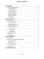
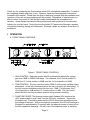
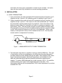
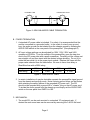
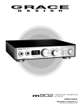
OWNERS MANUAL
MODEL 201
MICROPHONE PREAMPLIFIER
PO Box 204 Boulder, CO. 80306 303.443.7454 fax: 303.444.4634
Revision C March, 2000
© Copyright 1996, Lunatec LLC
TABLE OF CONTENTS
I. OPERATION . . . . . . . . . . . . . . . . . . . . . . . . . . . . . . . . . . . . . . . . . . . . . . . . . . . 2
A. FRONT PANEL CONTROLS . . . . . . . . . . . . . . . . . . . . . . . . . . . . . . . . . . . . . . . . . . . . . . . . 2
1. GAIN CONTROL
........................................................ 2
2. TRIM CONTROL
........................................................ 2
3. PHANTOM POWER . . . . . . . . . . . . . . . . . . . . . . . . . . . . . . . . . . . . . . . . . . . . . . . . . . . . . 2
4. PHASE REVERSE . . . . . . . . . . . . . . . . . . . . . . . . . . . . . . . . . . . . . . . . . . . . . . . . . . . . . . . 3
5. 20dB ATTENUATOR
.................................................... 3
6. PEAK INDICATOR . . . . . . . . . . . . . . . . . . . . . . . . . . . . . . . . . . . . . . . . . . . . . . . . . . . . . . . 3
7. MEMO PAD
............................................................. 3
B. SETTING THE GAIN . . . . . . . . . . . . . . . . . . . . . . . . . . . . . . . . . . . . . . . . . . . . . . . . . . . . . . . . 3
II. INSTALLATION . . . . . . . . . . . . . . . . . . . . . . . . . . . . . . . . . . . . . . . . . . . . . . . . 4
A. AUDIO TERMINATIONS . . . . . . . . . . . . . . . . . . . . . . . . . . . . . . . . . . . . . . . . . . . . . . . . . . . . 4
1. Input connections . . . . . . . . . . . . . . . . . . . . . . . . . . . . . . . . . . . . . . . . . . . . . . . . . . . . . . . . 4
2. Output connections . . . . . . . . . . . . . . . . . . . . . . . . . . . . . . . . . . . . . . . . . . . . . . . . . . . . . . . 4
3. 600 Ohm balanced cable . . . . . . . . . . . . . . . . . . . . . . . . . . . . . . . . . . . . . . . . . . . . . . . . . 4
B. POWER TERMINATION . . . . . . . . . . . . . . . . . . . . . . . . . . . . . . . . . . . . . . . . . . . . . . . . . . . . 5
1. AC power cable . . . . . . . . . . . . . . . . . . . . . . . . . . . . . . . . . . . . . . . . . . . . . . . . . . . . . . . . . . 5
2. AC input voltage . . . . . . . . . . . . . . . . . . . . . . . . . . . . . . . . . . . . . . . . . . . . . . . . . . . . . . . . . 5
a. Fuse table . . . . . . . . . . . . . . . . . . . . . . . . . . . . . . . . . . . . . . . . . . . . . . . . . . . . . . . . . . . . 5
3. AUDIO GND switch. . . . . . . . . . . . . . . . . . . . . . . . . . . . . . . . . . . . . . . . . . . . . . . . . . . . . . . 5
C. MECHANICAL . . . . . . . . . . . . . . . . . . . . . . . . . . . . . . . . . . . . . . . . . . . . . . . . . . . . . . . . . . . . . . 5
1. Rack mounting . . . . . . . . . . . . . . . . . . . . . . . . . . . . . . . . . . . . . . . . . . . . . . . . . . . . . . . . . . . 5
III. MAINTENANCE . . . . . . . . . . . . . . . . . . . . . . . . . . . . . . . . . . . . . . . . . . . . . . . 5
A. Introduction . . . . . . . . . . . . . . . . . . . . . . . . . . . . . . . . . . . . . . . . . . . . . . . . . . . . . . . . . . . . . . . . . 5
B. PEAK LED ADJUSTMENT PROCEDURE
.................................. 5
1. Equipment needed . . . . . . . . . . . . . . . . . . . . . . . . . . . . . . . . . . . . . . . . . . . . . . . . . . . . . . . 6
2. Procedure . . . . . . . . . . . . . . . . . . . . . . . . . . . . . . . . . . . . . . . . . . . . . . . . . . . . . . . . . . . . . . . . 6
C. Input offset adjustment . . . . . . . . . . . . . . . . . . . . . . . . . . . . . . . . . . . . . . . . . . . . . . . . . . . . . . 7
1. Equipment needed . . . . . . . . . . . . . . . . . . . . . . . . . . . . . . . . . . . . . . . . . . . . . . . . . . . . . . . 7
2. Procedure . . . . . . . . . . . . . . . . . . . . . . . . . . . . . . . . . . . . . . . . . . . . . . . . . . . . . . . . . . . . . . . . 8
IV. SPECIFICATIONS . . . . . . . . . . . . . . . . . . . . . . . . . . . . . . . . . . . . . . . . . . . . . 9
Page 1
Thank you for purchasing the Grace design model 201 microphone preamplifier. It is built to
be completely reliable and easy to use. However, there are some important instructions
included in this manual. Please take the time to familiarize yourself with the installation and
operation of the unit and most problems will be avoided. Regardless of what sources you
plan to record, the model 201 will be the invisible link between the microphone and
recorder. Grace Design has been building professional audio products for the recording
industry for over ten years. During this time the model 201 has evolved through a process
of extensive listening, testing and refinement. We hope it helps you achieve a new level of
excellence.
I. OPERATION
A. FRONT PANEL CONTROLS
Figure 5. FRONT PANEL CONTROLS
1. GAIN CONTROL Each gain control has 24 positions and adjusts the voltage
gain from 18dB to 64dB in 2dB steps. For reference, the 9 o'clock position is
30dB, the 12 o'clock position is 42dB, and the 3 o'clock position is 56dB.
2. TRIM CONTROL The trim control provides 10dB of continuously variable output
attenuation. In the fully clockwise position the trim is at unity (no attenuation). In
the fully counter-clockwise position the trim is at -10dB. For reference, the 3
o'clock position is -4dB and the 12 o'clock position is -8dB. The trim control
should be left in the fully clockwise position during normal recording.
3. PHANTOM POWER The phantom power switch (labeled 48V) connects the
+48V power supply to pins 2 and 3 on the XLR input connector. This switch
illuminates red. It should be noted that the LED in this switch actually monitors
the voltage at the input. With no microphone connected, the LED will continue to
illuminate for approximately 10 seconds after the phantom power is turned off as
the filter capacitors discharge. As well, even if the phantom power is switched
Page 2
off, the LED will illuminate if voltage is being fed from an external source. (i.e.
when using a direct split in a remote recording application.)
4. PHASE REVERSE The phase reverse switch (labeled ∅ ) reverses the absolute
polarity of the music signal at the input of the preamplifier. The switch illuminates
green and provides power for a sealed gold contact relay located on the
preamplifier circuit board. This eliminates signal wiring to the front panel and
switch contact performance problems.
5. 20dB ATTENUATOR The 20dB attenuator switch (labeled -20) attenuates the
input signal 20dB. The switch illuminates amber when engaged. Like the phase
reverse switch, this switch controls a sealed Gold contact relay on the
preamplifier circuit board. With the -20 switch engaged, the effective gain range
becomes -2dB to 44dB.
6. PEAK INDICATOR The LED peak indicator, which monitors the output signal,
turns green at -14dB and switches to red at +16dB (12dB before clipping in
balanced mode and 6dB before clipping in unbalanced mode). The threshold
level for peak indication is adjustable on each channel. See section V.
Maintenance.
7. MEMO PAD The Memo pad can be used with dry-erase or wet-erase type
markers. If using dry-erase markers, black is recommended. Grease pencils are
not recommended.
B. SETTING THE GAIN
1.
Turn the gain control fully counter-clockwise, turn the trim control fully clockwise
and check that the +48V phantom power is off. Connect the microphone and
then turn on the phantom power if required. When sending a signal to a tape
recorder that has fixed input levels, simply increase the gain until the optimum
recording level is reached. If the peak indicator flashes red excessively with the
gain control in the fully counterclockwise position, engage the -20dB attenuator.
2. When sending a signal to a tape recorder with an input attenuator use the
following procedure: With the sound source present, turn the preamplifier gain
control clockwise until the peak LED begins flashing red, then reduce the gain
until the red stops flashing. Since red indicates a peak level which is 12dB
before clipping (6dB in unbalanced mode) it is OK for it to come on periodically
during recording. If peak indicator flashes red excessively with the gain control in
the fully counterclockwise position, engage the -20dB attenuator. Adjust the
recorder input control for the optimum recording level.
3. The trim control can be used for ultra fine output level adjustment as well as for
level riding during recording. It should be noted that the maximum output level of
the preamplifier is reduced by the amount of output attenuation being used. For
instance, if the trim is set to -6dB the maximum output level of the preamplifier
will drop from +28dBu to +22dBu. Since the LED peak indicator monitors signal
Page 3
level before the trim control, preamplifier overload can be avoided. It is best to
leave the trim control fully clockwise for normal recording operations.
II. INSTALLATION
A. AUDIO TERMINATIONS
1. Input connections are made via female XLR connectors with pin 2 positive, pin 3
negative and pin 1 ground. 48V phantom power is supplied on pins 2 and 3.
2. Output connections are made via male XLR connectors with pin 2 positive, pin 3
negative and pin 1 ground. If the output is to be used unbalanced, pin 1 should
be connected to signal ground and pin 2 to signal hot. Due to the nature of the
balanced output stage, pin 3 should be left open for unbalanced operation. See
figure below. Note: This will provide a signal of positive absolute polarity when
the preamplifier is being used with microphone which produces a positive voltage
on pin 2 with positive air pressure on the front of the diaphragm. While a vast
majority of microphones conform to this standard a few do not. Use the phase
reverse switch to compensate if necessary.
2
1
HOT
GND
SHIELD
3 (OPEN)
Figure 1. UNBALANCED OUTPUT CABLE TERMINATION
3. The balanced output driver is capable of driving a matched 600Ω line. This type
of termination can be very advantageous for driving very long lines because it
provides maximum power transfer through the cable. With a higher power music
signal, aberrations caused by distributed capacitance and inductance in the
cable are minimized which improves transient performance and harmonic
integrity. To create a 600Ω balanced line, simply connect a 301Ω 1% metal film
resistor between pins 2 and 3 at the destination end of the cable. This
termination combines with the preamplifiers 300Ω output impedance to provide a
matched 600W line.
Page 4
RECORDER END
PREAMP END
2
1
1
2
301
3
3
Figure 2. 600Ω BALANCED CABLE TERMINATION
B. POWER TERMINATION
1. A standard AC power cable is included. For safety, it is recommended that the
cord be connected to a grounded outlet. In the event of noise from a ground
loop, the audio ground can be isolated from the chassis ground by throwing the
AUDIO GND switch on the rear panel of the preamplifier. (See paragraph 3)
2. AC input voltage settings can be adjusted for 100V, 120V, 220V and 240V
operation at 50-60Hz. From the outside of the preamplifier, open the trap door
next to the IEC power inlet with a small screwdriver. Carefully pull the voltage set
cam straight out and then insert with the desired voltage showing. Do not try to
rotate the cam while it is in the power input module. Replace the fuses with the
proper value selected from the table below. Be sure to use a time delay or
Slow-Blow fuse with a 250V rating
Voltage
100V
120V
220V
240V
Fuse rating
0.25A
0.25A
0.125A
0.125A
Figure 3. FUSE VALUE TABLE
3. In certain installations it may be desirable separate the preamplifier signal ground
from the chassis and earth grounds. Noise inducing ground loops can be broken
while retaining the safety feature of the grounded AC power cord. The 201
should not be operated with a ground lift or "cheater" plug on the AC power cord.
To isolate the audio ground from the chassis ground simply set the AUDIO GND
switch on the rear panel from EARTH to ISO.
C. MECHANICAL
1. The model 201 can be rack mounted in a standard 19" equipment rack. If
desired the rack mount ears can be removed by removing the 3 #6-32 flat head
Page 5
screws that hold each rack ear in place. After removing the rack ears replace the
two lower screws on each side of the preamplifier.
III. MAINTENANCE
A. The model 201 was designed to be maintenance free for many years. It is highly
unlikely that your unit will require service. However, there are two adjustments that
may need to be made from time to time. These procedures should be made only by
a qualified service technician or the Grace Design factory.
B. PEAK LED ADJUSTMENT PROCEDURE The peak LED threshold levels may be
adjusted to a user defined operating level. This circuit is set at the factory with the
green threshold at -14dBu and the red threshold at +16dBu. The relationship
between the two thresholds is fixed. The procedure for adjusting the red threshold
follows.
1. EQUIPMENT NEEDED
i. Sine wave audio signal generator or oscillator output from a mixing console.
ii. Audio level meter or VTVM
iii. Plastic alignment tool or small screwdriver
iv. Appropriate interconnect cables
v. #2 Phillips screwdriver
2. PROCEDURE
i. With the power off, remove the top cover from the 801. Set all of the gain
controls to the 9 O'clock position. (30dB gain)
ii. Connect the audio generator to the input of channel 1. Set the output level to
approximately -20dBu @1KHz. If the generator has an unbalanced output
refer to Figure 6 below for termination information.
2
XLR MALE
HOT
SHIELD
1
3
Figure 6. UNBALANCED INPUT CABLE
iii. Connect the level meter to the output of channel 1. Set the input attenuator to
+20dbu range. If the generator has an unbalanced input refer to Figure 1 for
termination information.
Page 6
iv. Apply power to the generator, preamplifier, then the level meter.
v. Adjust the generator output level so that the preamplifier output level is at the
desired red threshold. If the proper level can't be reached, adjust the
preamplifier gain control.
vi. Locate VR1 on the channel 1 audio circuit board. (See figure 7) Adjust VR1
until the peak LED is between green and red. The color should appear amber
when the setting is correct.
vii. Repeat this procedure for channel 2.
viii.If it is desired to calibrate the peak indicator to a specific tape recorder input
level, simply replace the level meter with the recorder. Adjust the signal
generator so that the desired peak level is indicated on the recorder and then
adjust VR1 until the peak LED is between green and red.
Figure 7. PEAK LED ADJ. VR1 AND OFFSET ADJ. VR2 LOCATIONS
C. INPUT OFFSET ADJUSTMENT: The input amplifiers in the 201 are ultra precision
laser trimmed devices that have a very low input offset. However, even the smallest
differential offset at the input can result in an audible "click" when the gain control is
turned. It should be noted that this type of click will be audible when no signal is
present. With no signal present there is no signal amplitude to be changed unless
input offset is present. The DC servo circuit in the 201 corrects any DC errors that
appear at the output of the instrumentation amplifier stage. It can not correct the
very small offset at the inputs. This procedure nulls the input offset and minimizes
the clicking sound with no signal present. In contrast, there will almost always be an
audible click if turning the gain control while a signal is present. This is because the
gain control, being a stepped control, will make an instantaneous change in
amplitude when turned, which creates a transient signal.
Page 7
1. EQUIPMENT NEEDED
i.
ii.
iii.
iv.
Oscilloscope with a DC coupled 10mV input range.
Unbalanced output cable. (see Figure 1.)
Plastic alignment tool or a small screwdriver.
#2 Phillips screwdriver
2. PROCEDURE
i. Remove the 12 #6-32 flat head screws from the top lid but leave the lid in
place.
ii. Set all of the preamplifier gain controls to minimum. Set the trim controls to
maximum. Turn on the 201 preamplifier and the oscilloscope and allow to
warm up for at least 45 minutes.
iii. Connect the output cable from channel 1 of the preamplifier to the
oscilloscope input.
iv. Set the oscilloscope vertical sensitivity to 10mV/division and input coupling to
DC.
v. Set the oscilloscope horizontal sweep rate to 0.5mS/division.
vi. Adjust the trigger for a stable sweep and the vertical position so that the trace
is on the zero line.
vii. Remove the top lid and locate potentiometer VR2. (See Figure 7.)
viii.While watching the scope, turn the gain control to the 12 o'clock position and
watch for the offset to change. If the trace moves in the positive direction
rotate VR2 in the clockwise direction. If the trace moves in the negative
direction rotate VR2 in the counter-clockwise direction. Adjust VR2 until the
trace is again on the zero line.
ix. Return the gain control to minimum gain. At this point the DC servo may have
developed a correction voltage in an attempt to zero the offset generated
while at the higher gain. Therefore the trace might not return exactly to the
zero line. What is important here is the relative offset between low and high
gain settings. Turn the gain control quickly between minimum and 12 o'clock
then back to minimum and watch the change in offset. Adjust VR2 so that the
trace stays still while turning the gain up and down. This step provides a
coarse adjustment. To make a fine adjustment repeat this step but turn the
gain control all the way to maximum and check that the offset is constant to
within plus or minus 10mV
x. Repeat steps vii and viii for channel 2.
xi. The input offset does drift with temperature and having the lid off will allow the
circuitry to cool. It is advisable to replace the lid and let the preamplifier warm
up again (about 20 minutes) and then recheck your adjustments.
Page 8
IV.SPECIFICATIONS
FREQUENCY RESPONSE
@ 40dB gain /± 0.2dB
@ 40dB gain /± 3dB
20Hz-300kHz
4.5Hz-1.0MHz
THD+N
@ 40dB gain +20dbu out
<.0015%
INTERMODULATION DISTORTION
@40dB gain +25dBu out
<.0025%
NOISE - REFERRED TO INPUT
@60dB gain 50 Ω source
-130dB
PHASE DEVIATION
50-20kHz
<2°
CROSSTALK
@40dB gain
-109dB
CMRR
@60dB gain, 3.5Vcm, 1kHz
@60dB gain, 3.5Vcm, 10kHz
Output CMRR
80dB
97dB
60dB
MAXIMUM OUTPUT LEVEL
Balanced
Unbalanced
+28dBu
+22dBu
IMPEDANCE
Input
Output
Minimum Load Impedance
1600Ω
150Ω
50Ω
GAIN RANGE
2dB steps
18-64dB
POWER CONSUMPTION
@120VAC 60Hz
15 Watts max.
WEIGHT
6.4 lbs.
DIMENSIONS
1U rack mount x 10" deep
Page 9