1
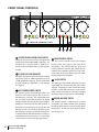
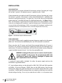
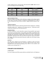
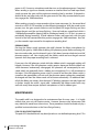
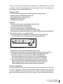
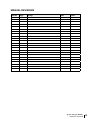
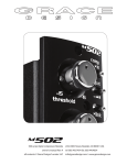
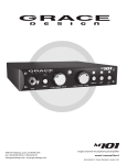
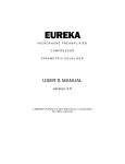
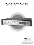
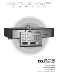
m801 microphone preamplifier Manual RevB owner’s manual all contents ©2006 Grace Design/ Lunatec LLC Welcome Thank you for purchasing the Grace Design m801 microphone preamplifier. With the combination of unmatched sonic performance and total reliability, the m801 is the ultimate, state of the art microphone preamplifier solution. We have designed the m801 to be as easy and intuitive to use as possible. However, we strongly recommend that you read this product manual thoroughly to familiarize yourself with the unique features and capabilities of the m801. Also, please do not hesitate to contact us directly if you have any questions, comments, or concerns with your new m801 microphone preamplifier. Thanks for reading and happy recording!! -The Grace Design Team Contents 2 Welcome 2 Important Safety Information 3 Front Panel Controls 4 Rearpanel Connections 5 Power Supply 5 Installation 6 Preamplifier Operation 7 Maintenance 8 Specifications 11 Cleaning and Maintenance 12 Warranty Information 12 grace design m801 owner’s manual Important Safety Information GENERAL •Indoor use only •Ordinary Protection: This equipment should not be exposed to dripping or splashing. •Avoid placing objects filled with liquids, such as vases or glasses, on this equipment. •Class I Equipment (grounded type) •Electrical rating: 100-120/220-240V~ 50-60Hz 60W •Mains supply voltage fluctuations are not to exceed ±10% of the nominal supply voltage. •Pollution Degree 2 •Installation (Overvoltage) Category II for transient overvoltages. •Maximum Relative Humidity: <80% •Operation temperature range: 10 °C to 40 °C •Storage and transportation temperature range –40 °C to 70 °C •Maximum altitude: 3000m (9843 ft) •Equipment suitable for continuous operation •Weight: preamplifier - 6.8kg (15lbs) / power supply unit - 2.8kg (6.25lbs) SAFETY MARKING SYMBOLS CAUTION: READ ACCOMPANYING DOCUMENTS This symbol, located on the equipment and in this manual, refers to important instructions. Read this manual thoroughly before operating this equipment. WARNING: ELECTRICAL SHOCK HAZARD This symbol, located on the equipment and in this manual, indicates the potential for electrical shock hazard. DC POWER OUTPUT This symbol, located on the equipment and in this manual, indicates a DC power output connection. SERVICE INFORMATION The Grace Design m801 contains no user serviceable components. Contact Grace Design for repair and upgrade information. In the event that your Grace Design m801 needs to be returned to the factory, contact us for a return authorization number. grace design m801 owner’s manual 3 Front Panel Controls A 1 B 2 40 30 50 20 +48V 60 - 20dB ribbon 3 40 30 50 20 +48V 4 40 30 60 50 20 - 20dB ribbon 60 30 50 20 - 20dB ribbon +48V 5 40 +48V 60 - 20dB ribbon GRACE DESIGN USA C A 24 position gold contact gain switch Each gain control has 24 positions and adjusts the voltage gain from 18dB to 64dB in 2dB steps. For reference, the 9 o’clock position is 28dB, the 12 o’clock position is 40dB, and the 3 o’clock position is 52dB. B bi-color LED peak indicator The LED peak indicator, which monitors the output signal, turns green at -14dB and switches to red at +16dB (12dB before clipping). The threshold level for peak indication is adjustable on each channel (see page 8). C 48V phantom power switch The phantom power switch (labeled +48V) connects the +48V power supply to pins 2 and 3 on the XLR input connector. This switch illuminates red. It should be noted that the LED in this switch actually monitors the voltage at the input. With no microphone connected, the LED will continue to illuminate for approximately 10 seconds after the phantom power is turned off as the filter capacitors discharge. As well, even if the phantom power is switched off, the LED will illuminate if voltage is being fed from an external source. (i.e. when using a direct split in a remote recording application.) 4 grace design m801 owner’s manual D D E F phase reversal switch The phase reverse switch reverses the absolute polarity of the music signal at the input of the preamplifier. The switch illuminates green and provides power for a sealed gold contact relay located on the preamplifier circuit board. This eliminates signal wiring to the front panel and switch contact performance problems. E -20 pad switch The 20dB attenuator switch attenuates the input signal 20dB. The switch illuminates amber when engaged. Like the phase reverse switch, this switch controls a sealed gold contact relay on the preamplifier circuit board. With the -20 switch engaged, the effective gain range becomes -2dB to 44dB. F ribbon mic mode switch This switch activates a 10dB increase in overall preamplifier gain while simultaneously disabling the 48V phantom power circuit to protect ribbon microphones. As well, the input coupling capacitors are bypassed. 4 30 20 +48V - Rearpanel Connections A 8 A XLR mic input connector B 7 pin XLR DC input 6 OUT B 5 C XLR output connector Output connections are made via male XLR connectors with pin 2 positive, pin 3 negative and pin 1 ground. parallel XLR output connector An additional set of parallel XLR outputs are provided for sending line signals to additional recording devices or mixers. m801 power supply front GRACE DESIGN +24 -24 +5 +48 BOULDER, CO USA O I CAUTION: ALWAYS CONNECT DC POWER CORD BEFORE TURNING ON MAIN POWER A B A LED Voltage indicators B Power switch C AC line input D DC output E Ground - ISO switch rear FOR m801 ONLY PUSH 120Vac 6 2 4 C 1 7 5 D 3 E grace design m801 owner’s manual 5 PUSH 1 3 2 5 D D An 8’ (2.8m) DC power cord is supplied to connect the power supply unit to the preamplifier unit. This cord can be identified by the 7 pin XLR connectors at each end. OUT A OUT B 7 C 5 6 OUT B 8 PUSH 1 OUT B MIC IN OUT A 7 Input connections are made via female XLR connectors with pin 2 positive, pin 3 negative and pin 1 ground. 48V phantom power is supplied on pins 2 and 3. 3 2 OUT A 8 B MIC IN 6 7 OUT A DC INPUT PUSH 1 3 MIC IN 2 2 PUSH MIC IN 3 PUSH m801 microphone preamplifier 1 GRACE DESIGN USA Installation AUDIO CONNECTIONS Input connections are made via female XLR connectors with pin 2 positive, pin 3 negative and pin 1 ground. 48V phantom power is supplied on pins 2 and 3. Output connections are made via male XLR connectors with pin 2 positive, pin 3 negative and pin 1 ground. If the output is to be used unbalanced, pin 1 should be connected to signal ground and pin 2 to signal hot. Due to the nature of the balanced output stage, pin 3 should be left open for unbalanced operation. See figure 1 below. Note: This will provide a signal of positive absolute polarity when the preamplifier is being used with a microphone which produces a positive voltage on pin 2 with positive air pressure on the front of the diaphragm. While a vast majority of microphones conform to this standard a few do not. Use the phase reverse switch to compensate if necessary. HOT 2 GND 1 SHIELD 3 (open) figure 1 - Unbalanced output cable termination POWER CONNECTIONS An 8’ (2.8m) DC power cord is supplied to connect the power supply unit to the preamplifier unit. This cord can be identified by the 7 pin XLR connectors at each end. Please note that the DC power cord should be connected before the AC power is turned on. This prevents incorrect power sequencing which can cause damage to the audio circuits. To avoid any interference with the low level audio circuitry, the power supply should be located at least 3’ (1m) from the preamplifier unit. WARNING: A damaged DC power cord can create a shock hazard as voltages of 72VDC can be present. Do not operate the m801 with a damaged DC power cord. Replace a damaeged DC power cord with a replacement from Grace Design. A standard AC power cable is included. For safety, the power supply cord must be connected to a grounded outlet. AC input voltage settings can be adjusted for 100V, 120V, 220V and 240V operation at 50-60Hz. If your line Voltage is 230VAC then use the 240V setting. From the rear of the power supply unit, open the trap door next to the IEC power inlet with a small screwdriver. Carefully pull the voltage select cam straight out and then insert with the desired voltage showing. Do not try to rotate the cam while it is in the power input 6 grace design m801 owner’s manual module. Replace the fuses with the proper value selected from table 1 below. Be sure to use a time delay fuse with a 250V rating. CAM SETTING LINE VOLTAGE FUSE VALUE 100V~ 100V~ 250V~ T 750mA L 120V~ 120V~ 250V~ T 750mA L 220V~ 220V~ 250V~ T 500mA L 240V~ 230V~ 250V~ T 500mA L 240V~ 240V~ 250V~T 500mA L table 1 - fuse value table CHECK LINE VOLTAGE SETTINGS The power supply unit has been set from the factory to operate at the voltage required for your part of the world. However, it’s important to double-check this in order to ensure no damage will come to the unit if power is applied while the setting is incorrect. TURNING THE POWER ON The power switch is located on the front panel of the Power Supply Unit. Switching the rocker switch to the I position turns the mains power on. Switching the rocker switch to the O position turns the mains power off. GROUNDING OPTIONS In certain installations, it may be desirable to separate the preamplifier signal ground from the chassis and earth grounds. Noise inducing ground loops can be broken while retaining the safety feature of the grounded AC power cord. The m801 should not be operated with a ground lift or “cheater” plug on the AC power cord. To separate the preamplifier signal ground from the chassis and earth grounds, simply set the AUDIO GND toggle switch on the rear panel of the power supply unit to the desired setting (ISO or EARTH). MOUNTING The m801 power supply can be rack mounted in a standard 1U rack tray, and two power supply units will fit side by side. The power supply unit chassis has a #10-32 threaded insert on the bottom for mounting. Use a #10-32 x 1/2” or a #10-32 x 3/8” machine screw, no longer than 1/2”. Preamplifier Operation SETTING THE GAIN First, turn the gain control fully counter-clockwise and check that the +48V phantom grace design m801 owner’s manual 7 power is off. Connect a microphone and then turn on the phantom power if required. When sending a signal to a recorder, converter or interface that has fixed input levels, simply increase the gain until the optimum recording level is reached. If the peak indicator flashes red excessively with the gain control in the fully counterclockwise position, engage the -20dB attenuator. When sending a signal to a tape recorder with an input attenuator (i.e. the record level control on a DAT or CDR recorder) use the following procedure: With the sound source present, turn the gain control clockwise until the peak LED begins flashing red, then reduce the gain until the red stops flashing. Since red indicates a peak level which is 12dB before preamplifier clipping (6dB in unbalanced mode), it is OK for it to come on periodically during recording. If peak indicator flashes red excessively with the gain control in the fully counterclockwise position, engage the -20dB attenuator. Now adjust the recorder input control for the optimum recording level. RIBBON MIC MODE Pressing the ribbon switch optimizes the m801 channel for ribbon microphones by boosting the gain by 10dB while disabling 48V phantom power. Before activating ribbon mic mode, make sure the channel’s gain is fully down (counter-clockwise) and 48V phantom power is off. Now simply press the ribbon switch and turn the gain control upwards until the proper recording level is achieved. If you press the 48V phantom switch while the ribbon switch is engaged, nothing will happen. However, if the 48V phamtom switch remains depressed and the ribbon mic switch becomes inadvertantly disengaged, 48V phantom will consequently be activated, which can potentially harm a ribbon your microphone if it is still connected to the input. If the 48V phantom power switch is turned of and then the ribbon switch is turned on the preamplifier will wait until the phantom power voltage has completely discharged and then the ribbon mode will activate automatically. An additional benefit of the ribbon mic mode is that the input DC blocking capacitors are relay bypassed to further simplify the m801’s signal path. Incidentally, the ribbon mode works very well with many lower output dynamic microphones as well as ribbon types. Maintenance The model m801 was designed to be maintenance free for many years. It is highly unlikely that your unit will require service. However, there are two adjustments that may need to be made from time to time. These procedures should be made only by a qualified service technician or the Grace Design factory. PEAK LED ADJUSTMENT PROCEDURE The peak LED threshold levels may be adjusted to a user defined operating level. This 8 grace design m801 owner’s manual circuit is set at the factory with the green threshold at -14dBu and the red threshold at +16dBu. The relationship between the two thresholds is fixed. The procedure for adjusting the greed / red threshold follows: EQUIPMENT NEEDED •Sine wave audio signal generator or oscillator output from a mixing console. •Audio level meter or VTVM with dBu or dBm scale •Plastic alignment tool or small screwdriver •Appropriate interconnect cables •#2 phillips head screwdriver PROCEDURE 1) With the power off, remove the eight phillips head screws from the top cover and remove it from the m801 2) Set all of the gain controls to the 30dB position 3) Connect the audio generator to the input of channel 1 4) Set the generator output level to approximately -20dBu @1KHz. 5) If the generator has an unbalanced output, refer to figure 2 below for termination information 6) Connect the level meter to the output of channel 1. 7) Set the input attenuator to +20dBu range. If the level meter has an unbalanced input, refer to figure 1 (p. 6) for unbalanced output termination information. HOT SHIELD 2 1 3 XLR MALE figure 2 - Unbalanced input cable 8) Apply power to the generator, preamplifier, then the level meter. 9) Adjust the generator output level so that the preamplifier output level is at the desired red threshold. If the proper level can’t be reached, adjust the preamplifier gain control. 10) Locate VR1 (see figure 3 p.10) on the channel 1 audio circuit board and adjust until the peak LED is between green and red. The color should appear amber when the setting is correct. Repeat this procedure for channels 2 through 8. 11) If it is desired to calibrate the peak indicator to a specific converter/recorder input level, simply connect the output of the preamplifer to the converter/recorder. Adjust the signal generator so that the desired peak level is indicated on the recorder and then adjust VR1 until the peak LED is between green and red. INPUT OFFSET ADJUSTMENT The input amplifiers in the m801 are ultra-precision laser trimmed devices which have a very low input offset. However, even the smallest differential offset at the input can result in an audible “click” when the gain control is turned. It should be noted that this type of click will be audible when no signal is present. With no signal present there is grace design m801 owner’s manual 9 no signal amplitude to be changed unless input offset is present. This procedure nulls the input offset and minimizes the clicking sound with no signal present. In contrast, there will almost always be an audible click if turning the gain control while a signal is present. This is because the gain control, being a stepped control, will make an instantaneous change in amplitude when turned, which creates a transient signal. EQUIPMENT NEEDED •DC Volt meter with at least 1mV sensitivity •Plastic alignment tool or a small screwdriver. •#2 phillips head screwdriver PROCEDURE 1) Remove the 8 phillips head screws from the top lid but leave the lid in place. 2) Set all of the preamplifier gain controls to maximum. 3) Turn on the m801 preamplifier and allow to warm up for at least 45 minutes. (go get a nice cup of coffee and do some stretches) 4) Remove the top lid and locate the DC offset test points TP1 and TP2 (figure 3). Place the Volt meter probes into these holes. 5) Locate DC offset potentiometer VR2 and rotate it for a reading of 0.000VDC +/- 0.003V. 6) The input offset does drift with temperature and having the lid off will allow the circuitry to cool. It is advisable to replace the lid and let the preamplifier warm up again (about 20 minutes) and then re-check your adjustments. VR2 (OFFSET ADJUST) TP1 AND TP2 (OFFSET TEST POINTS) +48 -18 +18 +15 -15 +5 C8 D8 J3 C11 D3 Q2 R23 R25 R22 C25 C27 R26 R24 U8 R30 R34 R31 D10 D9 Q3 R29 C30 R33 R32 U5 C4 C3 R12 R11 D1 C24 C29 C23 C28 grace design m801 owner’s manual C46 R40 R36 R39 C33 C32 U9 figure 3 - offset test point and peak LED adjust trimpots 10 J7 C39 R41 C31 D13 C34 R35 R38 C45 R37 K3 C44 U10 C40 R4 R2 C17 C16 C10 R20 D7 C9 D6 R19 R18 D5 R17 D4 R15 C5 U4 Q1 U7 C41 J5 C6 R16 R14 R13 C2 C1 R3 R1 D2 J2 U1 R45 R44 C35 L1 RED WIRE D12 C12 D11 C13 K4 C36 R27 R21 C21 C19 C18 R52 R5 K2 K1 C26 C14 U2 R42 U6 R7 R6 J8 C37 C15 C7 C42 R47 R46 R28 R43 R8 C38 TP2 D14 U3 AT132 REV TP1 L2 R9 OFFSET J4 C22 C20 R10 J1 VR1(PEAK LED ADJUST) R51 R50 R49 R48 C43 J6 Specifications PREAMPLIFIER SPECIFICATIONS FREQUENCY RESPONSE @ 40dB gain ± 3dB 50Ω source 4.5Hz-350KHz @ 40dB gain ± 0.2dB 50Ω source 18Hz-65KHz THD+N @ 20dB gain +20dBu out, 1kHz <.0008% @ 40dB gain +20dBu out, 1kHz <.0009% @ 60dB gain +20dBu out, 1kHz <.0070% INTERMODULATION DISTORTION @40dB gain +20dBu out SMPTE/DIN 1:1 (50Hz, 7kHz) <.0020% SMPTE/DIN 4:1 (50Hz, 7kHz) <.0030% NOISE - REFERRED TO INPUT @60dB gain 50Ω source -130dB @60dB gain 150Ω source -127dB @60dB gain 600Ω source -123dB PHASE DEVIATION 100-20KHz @40dB gain <3° CROSSTALK Any Channel @40dB gain 1kHz -140dB Any Channel @40dB gain 10kHz -130dB CMRR @60dB gain, 3.5Vcm, 1KHz >70dB @60dB gain, 3.5Vcm, 10KHz >70dB PHANTOM POWER Voltage +48V +0.9/ -0.0 6.8kΩresistor match tolerance +/- 0.1% MAXIMUM OUTPUT LEVEL 1kHz, 100KΩ load +28dBu IMPEDANCE Input 4350Ω Output 190Ω DIMENSIONS 15lbs (6.8kg) Weight Height 2U Width 19” 10” Depth POWER SUPPLY SPECIFICATIONS POWER CONSUMPTION 100-240VAC 50/60Hz 60 Watts max DIMENSIONS Weight 6.25lbs (2.8kg) Height 1.7” Width 8.5” Depth 8.5” grace design m801 owner’s manual 11 Cleaning and Maintenance Your m801 amplifier chassis is constructed out of high quality stainless steel. Under normal circumstances, virtually no maintenance is required to keep the unit looking shiny and new. However, if your unit becomes smudged or dirty, here are some cleaning tips: We recommend using either Pledge furniture polish or Zep brand stainless steel cleaner (available at the hardware store). Apply cleaner to a clean, dry, lint free cloth and gently wipe all stainless surfaces, taking care not to allow the cleaning product to build up around the panel switches or knobs. Warranty Information Grace Design warrants all of our products to be free of defective parts and workmanship for a period of five years.This warranty period begins at the original date of purchase and is transferable to any person who may subsequently purchase the product during this time. This warranty excludes the following conditions: normal wear and tear, misuse, customer negligence, accidental damage, unauthorized repair or modification, cosmetic damage and damage incurred during shipment. During the time of this warranty, Grace Design will repair or replace, at its option, any defective parts or repair defective workmanship without charge, provided the customer has appropriate proof of purchase and that the product has its original factory serial number. In order for Grace Design to provide efficient and timely warranty service, it is important that you mail the completed warranty registration card enclosed with all of our products within 10 days of the original date of purchase. You may also register your product directly with Grace Design by telephone (303-4437454 Monday-Friday 9:00am to 5:00pm MST), or you can register your product online at www.gracedesign.com. This warranty is in lieu of all other warranties whether written, expressed, or implied, INCLUDING ANY WARRANTIES OF MERCHANTABILITY OR FITNESS FOR A PARTICULAR PURPOSE. In no event will Grace Design be liable for lost profits or any other incidental, consequential or Exemplary damages, even if Grace Design is aware of the possibility of such damages. In no event will Grace Design’s liability exceed the purchase price of the product This warranty gives the customer specific legal rights. The customer may also have other rights, which vary from state to state. Some states do not allow limitations on implied warranties or consequential damages, so some of the limitations of the above may not apply to a particular customer. 12 grace design m801 owner’s manual Manual Revisions Revision Page Change Date Initials A all initial release 5/23/07 edg B all / 13 updated layout / added revision table 1/29/09 edg grace design m801 owner’s manual 13