1
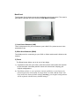
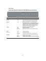
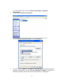
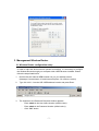
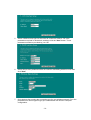
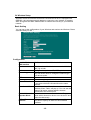
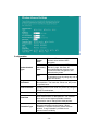
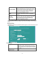
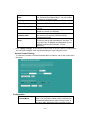
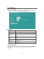
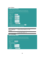
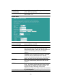
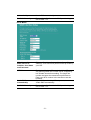
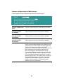
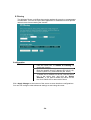
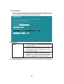
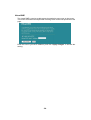
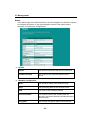
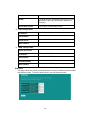
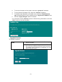
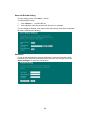
User’s Manual Wireless Broadband Router Model No. SP916GK http://www.micronet.info TABLE OF CONTENTS 1.1 INTRODUCTION ............................................................................................1 1.2 PACKAGE CONTENT....................................................................................1 1.3 FEATURES ....................................................................................................1 1.4 SPECIFICATIONS..........................................................................................2 BACK PANEL ...........................................................................................................3 FRONT PANEL .........................................................................................................4 2. INSTALLING AND USING WIRELESS ROUTER............................................5 2.1 Network configuration setup .......................................................................5 2.2 Computer configuration setup.....................................................................5 3. MANAGEMENT WIRELESS ROUTER ............................................................7 3.1 Wireless Router configuration setup ..........................................................7 3.2 Setup Wizard .................................................................................................8 3.3 Operation Mode Setup................................................................................11 3.4 Wireless Setup ............................................................................................12 BASIC SETTING ............................................................................................................................12 ACTIVE WIRELESS CLIENT TABLE.............................................................................................13 ADVANCED SETTING ...................................................................................................................13 SECURITY SETTING.....................................................................................................................15 ACCESS CONTROL SETTING .....................................................................................................16 WDS SETTING...............................................................................................................................17 3.5 TCP/IP Setting .............................................................................................18 LAN INTERFACE SETTING...........................................................................................................18 WAN INTERFACE SETTING .........................................................................................................18 STATIC IP MODE...........................................................................................................................19 DHCP CLIENT MODE....................................................................................................................19 PPPOE MODE ...............................................................................................................................20 PPTP MODE ..................................................................................................................................21 COMMON CONFIGURATIONS FOR WAN INTERFACE .............................................................22 3.6 Firewall Configuration ................................................................................23 PORT FILTERING..........................................................................................................................23 IP FILTERING ................................................................................................................................24 MAC FILTERING............................................................................................................................25 PORT FORWARDING....................................................................................................................26 URL FILTERING.............................................................................................................................27 VIRTUAL DMZ................................................................................................................................28 3.7 Management ................................................................................................29 STATUS..........................................................................................................................................29 STATISTICS ...................................................................................................................................30 DDNS..............................................................................................................................................31 TIME ZONE SETTING ...................................................................................................................31 SYSTEM LOG ................................................................................................................................31 UPGRADE FIRMWARE .................................................................................................................32 SAVE AND RELOAD SETTING .....................................................................................................33 PASSWORD...................................................................................................................................33 Product Specifications .....................................................................................34 Appendix A ........................................................................................................35 Glossary ............................................................................................................36 1.1 Introduction Thank you for purchasing Micronet SP916GK Wireless Broadband Router. SP916GK with built-in 4-port 10/100Mbps Fast Ethernet Switch is the latest generation of Wireless router product for Home/Office and SOHO users. This fullfeature and self-contained compact Wireless Router will allow broadband access in both of LAN and Wireless environment. This device has been specifically designed to provide LAN and Wireless users the most cost-effective method with multiple accesses to the Internet. Using just single public IP address (IP Sharing) SP916GK enables multiple users to share the Internet through an ADSL or cable modem. The friendly WEB-based graphics interface makes setup easy for any inexperienced users. Moreover, the built-in 4-port 10/100Mbps switch lets users enjoy the network by simply plugging in the network cable into the device without the need to buy additional switch. This device is also an Access Point. It has a built-in wireless LAN. Users can connect to Internet using wireless network interfaces anywhere within the range of its radio transmission. It’s ideal for SOHO users who require instant and convenient access to Internet without connecting cables. It has embedded DHCP server and simplified IP address management. There’s no need for MIS personnel to take care of daily technical services. What is more, NAT/firewall is also implemented on this compact Router Box for protecting whole LAN from outside attack. This user guide is aimed at easy installation procedures of this device. Before your installation, please read the following procedures carefully. 1.2 Package Content Before you start installing the product, please verify the following items are in the package: • • • • • • Wireless Broadband Router Quick Installation Guide Manual CD Detachable antenna Accessories Power adapter 1.3 Features • • • • • • Complies with IEEE 802.11b/g wireless standards Provides one 802.11b/g wireless Reverse SMA detachable antenna High speed transfer data rate up to 54Mbps Supports wireless data encryption with 64/128-bit WEP, WPA (TKIP with IEEE 802.1x), WPA2 and AES functions Supports system log Supports authentication for wireless connectivity based on ESSID -1- • • • • • • • • • • • • Provides MAC access control and hidden SSID function WDS supported with WEP, TKIP and AES encryption Channel : USA 11, Europe 13, Japan 14 Supports NAT/NAPT IP Sharing Supports Static IP, PPPoE, PPTP, & DHCP client SPI Anti-DoS Firewall; Virtual DMZ; DNS relay; UPnP Provides DHCP server Supports VPN pass through Supports ALG for FTP, NetMeeting, VPN pass-through, DDNS (DynDNS, TZO) Supports firmware upgrade function via Web Compliant with FCC Part 15.247 for US, ETS 300 328 for Europe Flash : 2MB NOR type, SDRAM : 8MB 1.4 Specifications • • • • • • • • • • • • • • • Standards: IEEE 802.11b/g (Wireless), IEEE 802.3, IEEE 802.3u (Ethernet) Data Rate: 54/48/36/24/18/12/11/9/6/5.5/2/1Mbps auto fallback Security: 64/128-bit WEP Data encryption, WPA, 802.1x, and Access Control List Frequency Band: 2.400~2.4835GHz (Industrial Scientific Medical Band) Radio Technology: OFDM/ DSSS Antenna: External detachable dipole antenna (with RP-SMA connector) Receiver Sensitivity: 54Mbps OFDM, 10%PER, -71dBm 11Mbps CCK, 10%PER, -81dBm 1Mbps BPSK, 10%PER, -92dBm Connectors: 4 RJ-45 LAN ports of 10/100M, and 1 RJ-45 WAN port Power: 12VDC, 1A Transmit Power: 16~18dBm (Typical) LEDs: Power, LAN Link/Activity, WAN Link/Activity, Wireless Activity Dimension/Weight: Temperature: Operating: 00 ~ 400C (320 ~ 1040F) Humidity: 10-90% (Noncondensing) Certification: FCC, CE Note The WAN “idle timeout” auto-disconnect function may not work due to abnormal activities of some network application software, computer virus or hacker attacks from the Internet. For example, some software sends network packets to the Internet in the background, even when you are not using the Internet. So please turn off your computer when you are not using it. This function also may not work with some ISP. So please make sure this function can work properly when you use this function in the first time, especially your ISP charge you by time used. -2- Back Panel The diagram (fig1.0) below shows the broadband router’s back panel. The router’s back panel is divided into three sections, LAN, WAN and Reset: 1) Local Area Network (LAN) The 4 LAN ports are for you to connect to your LAN’s PCs, printer servers, hubs and switches etc. 2) Wide Area Network (WAN) The WAN port is for connecting to your xDSL or Cable modem and is linked to the Internet. 3) Reset The Reset button allows you to do one of two things. 1) If problem occurs with your router, press the router’s reset button with a pencil tip (for less than 4 seconds) and the router will re-boot itself, keeping your original configurations. 2) If problem persists, or you experience extreme problems, or you forgot your password, press the reset button for longer than 4 seconds, and the router will reset itself to the factory default settings (warning: your original configurations will be replaced with the factory default settings) -3- Front Panel On the router’s front panel, there are LED lights that inform you of the router’s current status. Below is an explanation of each LED and what each stands for. LED Light Status PWR ON Status ON WAN ON Off Flashing LAN ON Off Flashing LAN is connected No LAN connection LAN port has Activity (ACT), data being sent ON Off Flashing Wireless LAN has been activated(steady green) Wireless LAN is disabled Wireless LAN has Activity (ACT) data being sent (Port 1-4) WLAN Description This indicator lights green when the Wireless Router is receiving power; otherwise, it is off. The LED will be off for a few seconds when the system is starting. The LED will then start to blink periodically to show the Wireless Router is working normally. If the LED stays green/off, it means the system failed; you need to contact your agent or try to reboot the system WAN is connected (steady green) No WAN connection WAN port has Activity (ACT), data being sent -4- 2. Installing and Using Wireless Router This Chapter provides a step-by-step guide to the installation and configuration of the Wireless Router. We suggest you go over the whole chapter before doing more advanced operation. 2.1 Network configuration setup Steps to build up the network: Step1. Connect the ADSL or Cable modem to the Ethernet WAN port on the back of the Wireless Router by using the UTP cable. Step2. Connect the phone line from the wall socket to the line-in port on the ADSL modem, or the coaxial cable to the line-in port on the Cable modem. Step3. Plug in the power adapter to the modem and turn on the power. Install the Ethernet card into the computer by referring to the User Guide that came with the card. Step4. Connect the computer to the Wireless Router by using standard twisted-pair Ethernet cable from the computer’s Ethernet card to a 10/100Mbps Ethernet port on the back of the Wireless Router. Step5. Plug in the power adapter to the Router and the other side to the wall outlet. 2.2 Computer configuration setup In order to communicate with this Wireless Router, you have to configure the IP addresses of your computer to be compatible with the device. The router supports DHCP server, which is enabled as default. Users using “Obtain an IP address automatically” to configure IP address may skip the following IP configuration instruction section. Note: 1. The default network setting of the device: IP address: 192.168.1.1 Subnet Mask: 255.255.255.0 DHCP Server: enabled 2. In the following TCP/IP configuration guide, the IP address “192.168.1.2 ” is assumed to be your IP address if you want to specify IP addresses manually. Please DO NOT use 192.168.1.1 as the IP address for 192.168.1.1 has been set as the default IP for this device. 3. The following TCP/IP configuration guide uses Windows XP as the presumed operation system. Procedures to configure IP addresses for your computer 1. If you are in Classic Start menu view, click StartÆSettingsÆControl PanelÆNetwork Connections. -5- 2. If you are in Start menu view, click StartÆControl PanelÆ Network Connections. Double click “Local Area Connection” 3. Choose Internet Protocol (TCP/IP) and click Properties. 4. You may choose “Obtain an IP address automatically” (recommend) to get IP address automatically or choose “Use the following IP address” to specify IP addresses manually. Please click the OK button after your configuration. -6- 3. Management Wireless Router 3.1 Wireless Router configuration setup In order to make the whole network operate successfully, it is necessary to configure the Wireless Router through your computer with a WEB browser installed. Please follow the steps listed below. 1. Double click the Internet WEB browser icon on your desktop screen (Netscape Communicator 4.0 and Internet Explorer 3.0 or above version) 2. Type 192.168.1.1 into the URL WEB address location and press Enter. 3. The Username and Password Required window appears. - Enter admin in the User Name location (default value). - Enter admin in the Password location (default value). - Click “OK” button -7- 4. The Graphic User Interaface After the password authorization, the Setup Wizard shows up as the home page of the Graphic User interface. You may click on each folder on left column of each page to get access to each configuration page. 3.2 Setup Wizard If you are using the router for the first time, you may follow the procedures of the setup wizard to do a step-by-step configuration. Note: The following instruction does an overall introduction to the Setup Wizard. For detail information to each item, please refer to instruction of each page. 1. To start the Setup Wizard, click the “Next” button to proceed. -8- 2. Select your demanding operation mode and click “Next”. 3. Mark the check box to enable synchronizing time by NTP server. Select the religion you live in and a NTP server by clicking the drop list, then click “Next” 4. Specify an IP address and subnet mask for connecting to the router in LAN. -9- 5. Select a WAN access type for the router to connect to Internet. Fill in the parameters required in each blank, and then click the “Next” button. Those parameters should be provided by your ISP. 6. Select the wireless parameters that are used for associating with this router and click “Next” 7. Click the drop list to select the encryption type for your wireless network. Fill in the parameters for the encryption type you selected and click finish to complete configuration. - 10 - 3.3 Operation Mode Setup To select an operation mode for this router, click on the mode that you want to perform and click the button to execute. - 11 - 3.4 Wireless Setup Wireless Access Point builds a wireless LAN and can let all PCs equipped with IEEE802.11b/g wireless network adaptor to connect to your Intranet. It supports WEP encryption and MAC address filter to enhance the security of your wireless network. Basic Setting You can set up the configuration of your Wireless and monitor the Wireless Clients associate with your AP. Configuration Disable Wireless LAN Interface To Disable interface of Wireless LAN To select a band for this device to match 802.11b, 802.11g or both. Configure this device as AP, WDS or both. Mode When you configure this device in AP mode, this Network type drop list allows users to change the network type into ad-hoc mode. The name of the wireless network SSID Select the region you live in. Country The channel used by the wireless LAN. All devices Channel Number in the same wireless LAN should use the same channel. Associated Clients Click "Show Active Clients" button, then an "Active Wireless Client Table" will pop up. You can see the status of all active wireless stations that are connected to the access point. Mark this checkbox to enable Universal Repeater Enable Universal Mode which allows this device to act as an AP and Repeater Mode client simultaneously. SSID of Extended While you enable the Universal Repeater Mode, you have to specify an SSID for the extended Interface interface. Band - 12 - Click <Apply changes> button at the bottom of the screen to save the above configurations. You can now configure other advanced settings or start using the router (with the advance settings in place) Active Wireless Client Table This is the window that pops up after clicking the “Show Active Clients” button. MAC Address MAC address of this active wireless station. Tx Packet The number of transmitted packets that are sent out from this active wireless station. The number of received packets that are received by this active wireless station. The transmission rate Rx Packet TX Rate Refresh Shows if the wireless client is in Power Saving mode This is the time in second before dissociation. If the wireless keeps idle longer than the expired time, this wireless router will dissociate it. The wireless client station has to re-associate when it is active. Refresh the "Active Wireless Client Table". Close Close the "Active Wireless Client Table". Power Saving Expired Time Advanced Setting You can set advanced wireless LAN parameters of this router. The parameters include Authentication Type, Fragment Threshold, RTS Threshold, Beacon Interval, Data Rate, Preamble Type, Broadcast SSID, IAPP and 802.11g Protection. We recommend not changing these parameters unless you know what these changes will do to the router. - 13 - Configuration Open System mode Authentication Type Fragment Threshold RTS Threshold Beacon Interval Data Rate Preamble Type Wireless AP can associate with this wireless router without WEP encryption. You should also set up WEP key in the Shared Key "Security" page. Wireless AP associated with this wireless router mode should use WEP encryption in the authentication phase. The wireless client can associate with Auto this wireless router by using any one of these two Modes. Specifies the maximum size of packet during the data transition. The lower the values set, the poorer the performance. If the packet size is smaller the RTS threshold, the wireless router will not send this packet by using the RTS/CTS mechanism. Specifies the period of time for a beacon broadcast. The "Data Rate" is the highest limit for wireless router transmission of data packets. The wireless router will use the highest possible selected transmission rate to transmit the data packets. It defines the length of CRC block in the frames during the wireless communication. "Short Preamble" is suitable for heavy traffic wireless network. "Long Preamble" provides more communication reliability - 14 - Broadcast SSID IAPP 802.11g Protection If you enable "Broadcast SSID", every wireless station located within the coverage of this wireless router can find this wireless router easily. If you are building a public wireless network, enabling this feature is recommended. Disabling "Broadcast SSID" can provide better security. Enables multiple AP to communicate and pass information regarding the location of associated Stations. Some 802.11g wireless adapters support 802.11g protection, which allows the adapters to search for 802.11g singles only. Select the “Disabled” to disable supporting 802.11g protection or select “enable” to support this function. Click the <Apply Changes> button at the bottom of the screen to save the above configurations. You can now configure other advanced settings or start using the router. Security Setting At the page, you can set up the WEP, WPA Encryption to ensure the security of your Wireless network. Configuration Encryption Use 802.1x Authentication To enable WEP, WPA, WPA2 and WPA2 Mixed encryption modes, select the option in the drop list. If you select none, all data will be transmitted without Encryption and every station can access the router. To enable the 802.1x, click the check box of the item. - 15 - WPA Cipher Suite There are two items, “Enterprise (WPA-Radius)” and “Personal (Pre-Shared Key)”. You can select the mode by clicking the item. Select the WPA Cipher Suite to be TKIP or AES WPA2 Cipher Suite Select the WPA2 Cipher Suite to be TKIP or AES WPA Authentication Mode Pre-Shared key Format To define the format, select what you need in the drop list. Enter the Pre-shared Key according to the prePre-shared Key shared key format you selected. Mark this checkbox to enable Pre-authentication Enable Preafter selecting Enterprise (RADIUS) WPA 2 Authentication authentication mode Authentication RADIUS If you use RADIUS Sever to ensure your security, you have to set up the parameters in this item. To Sever set up the Port, IP address and Password of your RADIUS, enter the Port Number, IP and Password. Click <Apply Change> at the bottom of the screen to save the above configurations. You can now configure other advanced settings or start using the router. Access Control Setting To restrict the number of access authentication of stations, set up the control list in this page. Configuration Wireless Access Control Mode Click on the drop list to choose the access control mode. You may select “Allow listed” to allow those allowed MAC addresses or select “Deny Listed” to ban those MAC addresses from accessing to this - 16 - MAC Address & Comment Current Access Control list device. To set up the Value of MAC Address & Comment; enter the MAC Address and Comment of the station and click Apply Changes to save. To delete the station from the list, click the check box in the select item and click the “Delete Selected”. If you want to delete all stations on the list, click “Delete All” to remove all of them. Click <Apply Change> at the bottom of the screen to save the above configurations. You can now configure other advanced settings or start using the router WDS Setting Wireless Distribution System allows the router to communicate with other APs wirelessly. To make it work, you must ensure that these APs and the Router are in the same Channel and add these APs MAC Address and Comment values into the WDS list. Don’t forget to enable the WDS by clicking the check box of “Enable WDS” and pressing “Apply Changes” button to save. To Delete an AP from the list, click the check box in the select item and click the “Delete Selected”. If you want to delete all APs on the list, click “Delete All” to remove all of them. - 17 - 3.5 TCP/IP Setting LAN Interface Setting This sections cover how to set up the configuration of LAN interface, Private IP of you router LAN Port and Subnet mask for your LAN segment. Configuration IP address The IP of your Router LAN port (Default 192.168.1.1) Subnet Mask Subnet Mask of you LAN (Default 255.255.255.0) DHCP Server DHCP Client Range 802.1d Spanning tree Enable UPnP To give your LAN Client an IP, you have to enable “DHCP Server”. Setting up your client IP manually is necessary when you want to use the router as your client’s default gateway. Specify the DHCP Client IP address range. You can also click the “Show Client” button to list the connected DHCP clients. To prevent from network loops and preserve the quality of bridged network Mark this checkbox to allow this router to be recognized by UPnP. WAN Interface Setting This page allows users to configure those parameters for connecting to Internet. You may select the WAN Access Type from the drop list and configure parameters for each mode. - 18 - Static IP Mode IP Address, Subnet Mask and Default Gateway Fill in the IP address, Subnet Mask and Default Gateway that provided by your ISP. DNS 1, 2 and 3 To specify the DNS, and enter the DNS provided by your ISP in DNS 1 2 3. DHCP Client Mode - 19 - Attain DNS automatically: If your DNS provided by ISP is dynamic, choose “Attain DNS automatically Set DNS Manually To specify the DNS, enter the DNS provided by your ISP in DNS 1 2 3. PPPoE Mode User Name, password and service name Fill in the User Name, password and service name that provided by your ISP. Connection Type “Continuous” is for Always keeping connection Idle Time: MTU Size Attain DNS “Connect on demand” is for billing by connection time. You can set up the Idle time for the value specifies the number of time that elapses before the system automatically disconnects the PPPoE session. “Manual” is to connect to ISP manually. Click “Connect” from the WEB user interface. The WAN connection will not disconnect due to the idle timeout. If the WAN line breaks down and later links again, the router will not auto-connect to the ISP. Defines the amount of idle time that elapses before the system automatically disconnects the PPPoE session. Enable the Maximum Transmission Unit of the router. Any packet greater than this number will be chopped up into suitable size before sending. The larger the number, the better transmission performance. Enter your MTU number in the text-box to set the limitation. If your DNS provided by ISP is dynamic, choose - 20 - automatically: “Attain DNS automatically Set DNS Manually To specify the DNS, enter the DNS provided by your ISP in DNS 1 2 3. PPTP Mode IP Address, Subnet Mask, Server IP Address, User Name and Password Fill in the IP address, Subnet Mask, Server IP Address, User Name and password that provided by your ISP. MTU Size Enable the Maximum Transmission Unit of Router. Any packet greater this number will be chopped up into suitable size before sending. The larger the number the better the transmission performance. Enter your MTU number in the text-box to set the limitation. If your DNS provided by ISP is dynamic, choose “Attain DNS automatically Attain DNS automatically: Set DNS Manually To specify the DNS, enter the DNS provided by your ISP in DNS 1 2 3. - 21 - Common configurations for WAN interface Some settings can be configured with each WAN access types: Enable Web Server Access on WAN from port To enable the user to access this Router through Internet, enter the specific IP and the port number Enable IPsec pass through on VPN connection Mark the check box to enable IPsec pass through on VPN connection; clear the checkbox to disable. Enable PPTP pass through on VPN connection Mark the check box to enable PPTP pass through on VPN connection; clear the checkbox to disable. Enable L2TP pass through on VPN connection Mark the check box to enable L2TP pass through on VPN connection; clear the checkbox to disable. Clone MAC Address When ISP use MAC address authentication (with DHCP), then the MAC address of the Ethernet card attached to your Cable modem must be registered with the ISP before connecting to the WAN (Internet). If the Ethernet card has changed, the new MAC address must be registered with the ISP. MAC cloning feature allows the MAC address reported by WAN side network interface card to be set to the MAC address already registered with the ISP, eliminating the need to register the new MAC address with the ISP. This feature does not change the actual MAC address on the NIC, but instead changes the MAC address reported by Wireless Router to client requests. To Change the MAC address, enter it in the text box. - 22 - 3.6 Firewall Configuration Port Filtering The firewall not only can obstruct outside intruders from intruding your system, but also restricting the LAN users. Port Filtering can be used to restrict certain type of data packets from your LAN to Internet through the Router by adding it on the Current Filtering Table. Configuration STEPS 1. Click the check box of “Enable Port Filtering” to enable the function. 2. Enter the Port range (EX 25-110), Protocol (UDP/TCP), and comment (EX. E-Mail) 3. To delete the port range on the list, click the check box in the select item, and click the “Delete Selected”. If you want to delete all entries on the list, click “Delete All” to remove all of them. Click <Apply Change> at the bottom of the screen to save the above configurations. You can now configure other advanced settings or start using the router. - 23 - IP Filtering The Wireless Router could filter the outgoing packets for security or management consideration. You can set up the filter against the IP addresses to block specific internal users from accessing the Internet. Configuration STEPS 1. Click the check box of “Enable IP Filtering” to enable the function. 2. Enter the specific Local IP address (EX 10.10.3.9), Protocol (UDP/TCP), and comment (EX. Peter) 3. To delete the IP address on the list, click the check box in the select item, and click the “Delete Selected”. If you want to delete all entries on the list, click “Delete All” to remove all of them. Click <Apply Change> at the bottom of the screen to save the above configurations. You can now configure other advanced settings or start using the router. - 24 - MAC Filtering The Wireless Router could filter the outgoing packets for security or management consideration. You can set up the filter against the MAC addresses to block specific internal users from accessing the Internet. Configuration STEPS 1. Click the check box of “Enable MAC Filtering” to enable the function. 2. Enter the specific MAC address (EX 00:0e:b6:a8:72), and comment (EX. Peter) 3. To delete the MAC address on the list, click the check box in the select item, and click the “Delete Selected”. If you want to delete all entries on the list, click “Delete All” to remove all of them. Click <Apply Change> at the bottom of the screen to save the above configurations. You can now configure other advanced settings or start using the router. - 25 - Port Forwarding The Port Forwarding allows you to re-direct a particular range of service port numbers (from the Internet/WAN Ports) to a particular LAN IP address. It helps you to host some servers behind the router NAT firewall. Configuration STEPS 1. Click the check box of “Enable port forwarding” to enable the function. 2. Enter the specific IP address (EX 10.10.10.10), Protocol (UDP/TCP), Port range (EX 25-110), and comment (EX. E-Mail) 3. To delete the IP address on the table, click the check box in the select item and click the “Delete Selected”. If you want to delete all entries on the table, click “Delete All” to remove all of them. Click <Apply Change> at the bottom of the screen to save the above configurations. - 26 - URL Filtering The URL Filter allows users to prevent certain URL from being accessed by users in LAN. This filter will block those URLs that contain certain keywords. Configuration STEPS 1. Click the check box of “Enable URL Filtering” to enable the function. 2. Enter the URL to be banned. 3. To delete the URL on the table, click the check box in the select item, and click the “Delete Selected”. If you want to delete all URLs on the table, click “Delete All” to remove all of them. Click <Apply Change> at the bottom of the screen to save the above configurations. - 27 - Virtual DMZ The virtual DMZ is used to enable protocols needed to open ports on the router. The router will forward all unspecified incoming traffic to the host specified in this page. Enter the Host IP (private IP address), and click “Apply changes” to activate the setting. - 28 - 3.7 Management Status In the home page of the Wireless Router, the left navigation bar shows the options to configure the system. In the right navigation screen is the system status summary for viewing the configurations. System Uptime The amount of time that the device is power on. Firmware Version The version of the firmware applied on this device. Wireless Configuration Mode The operation mode of the wireless router Band The performing band of this wireless router SSID The name of this wireless network Channel Number The channel used by the wireless LAN. All devices in the same wireless LAN should use the same channel Encryption The security encryption status of this wireless - 29 - network BSSID The Basic Service Set Identity of this router.(This parameter is the same as the MAC address of LAN port) Associated Clients The number of associated clients. LAN Configuration IP Address Subnet Mask DHCP Server MAC Address IP Address of router Subnet Mask of the router Status of DHCP server: Enabled or Disable MAC Address of LAN-port WAN Configuration Attain IP Protocol IP Address Subnet Mask Default Gateway MAC Address Static IP address IP address of WAN-port Subnet Mask of WAN-port Default Gateway of WAN-port MAC Address of WAN-port Statistics This page shows the sent & received packets counters of wireless, Ethernet LAN, and Ethernet WAN. To see the latest report, click the Refresh button. - 30 - DDNS This page allows users to connect to DDNS. To enable DDNS, mark the “Enable DDNS” checkbox. Select the service provider from the drop list. Fill in domain name, username, and password. Click the “Apply Change” button after configuration. Time Zone Setting This page allows users to configure the time setting of the router. To specify manually, fill in the blanks in “Current Time” and click the “Apply Change” button. To synchronize time from a timeserver, please mark the “Enable NTP client update” checkbox, select a NTP server from the drop list or manually enter a NTP server. Click the “Apply Change” button after your configuration System Log This System Log page shows the information of the current activities on the router. To enable system log function: 1. Mark the “Enable Log” checkbox. - 31 - 2. To see all information of the system, select the “system all” checkbox. 3. To see wireless information only, select the “wireless” checkbox. 4. To send the log information to a certain note, select the “Enable Remote Log” checkbox and fill in the IP address in the “Log Server IP Address” box. 5. Click the “Apply Changes” button to activate You could also click the “Refresh” button to refresh the log information or click the “clear” button to clean the log table. Upgrade Firmware To Upgrade Firmware STEPS 1. Click “browse…” button to select the firmware you want to upgrade. 2. Click Upload to start the upgrade process. Please don’t close the WEB-browser and wait for process to complete. When Upgrade is completed, you can start to use the router. - 32 - Save and Reload Setting To save setting to file, click “Save...” button. To load setting from file, 1. Click “Browse…” to select the file 2. Click upload to start the process and wait for it to complete To reset setting to Default, click reset to start the process, and when completed, the status LED will start blinking. Password To set up the Administrator Account information, enter the Username, New password, and reenter the password on the text box. Don’t forget to click the “Apply Changes” to save the configuration. - 33 - Product Specifications Standard Interface WAN Connection Cable Connections Network Data Rate Transmission Mode LED indicators Security Receiver Sensitivity Transmit Power Range Coverage Emission Operating Temperature Operating Humidity Power Supply IEEE802.3, 10BASE-T IEEE802.3u, 100BASE-TX IEEE802.3x full duplex operation and flow control IEEE802.11b wireless LAN infrastructure IEEE802.11g wireless LAN infrastructure 1 * WAN port 4 * 10/100 RJ-45 Fast Ethernet switching ports Antenna: 802.11b/g wireless reverse SMA detachable Ethernet 10/100 Mbps RJ-45 (10BASE-T): Category 3,4,5 UTP RJ-45 (100BASE-TX): Category 5 UTP 802.11b: 1, 2, 5.5 and 11Mbps 802.11g: 6, 9, 12, 18, 24, 36, 48, and 54Mbps Auto-Negotiation (Full-duplex, Half-duplex) System: Power, Status Port (WAN): ACT/LINK Port (LAN): ACT/LINK Port(Wireless): ACT 64/128-bit WEP, WPA(TKIP with IEEE 802.1x), WPA2, AES 54Mbps OFDM, 10%PER, -71dBm 11Mbps CCK, 10%PER, -81dBm 1Mbps BPSK, 10%PER, -92dBm 16dBm~18dBm Indoor 35~100 meters Outdoor 100~300meters. FCC CLASS B, CE, VCCI Class B 00 ~ 400C (320 ~ 1040F) 10% - 90% External Power Adapter, 12VDC/ 1A - 34 - Appendix A How to Manually find your PC’s IP and MAC address 1) In Window’s open the Command Prompt program 2) Type Ipconfig /all and <enter> • • • Your PC’s IP address is the one entitled IP address (192.168.1.77) The router’s IP address is the one entitled Default Gateway (192.168.1.254) Your PC’s MAC Address is the one entitled Physical Address (00-50-FC-FE-02-DB) - 35 - Glossary Default Gateway (Router): Every non-router IP device needs to configure a default gateway’s IP address. When the device sends out an IP packet, if the destination is not on the same network, the device has to send the packet to its default gateway, which will then send it out towards the destination. DHCP: Dynamic Host Configuration Protocol. This protocol automatically gives every computer on your home network an IP address. DNS Server IP Address: DNS stands for Domain Name System, which allows Internet servers to have a domain name (such as www.Broadbandrouter.com) and one or more IP addresses (such as 192.34.45.8). A DNS server keeps a database of Internet servers and their respective domain names and IP addresses, so that when a domain name is requested (as in typing "Broadbandrouter.com" into your Internet browser), the user is sent to the proper IP address. The DNS server IP address used by the computers on your home network is the location of the DNS server your ISP has assigned to you. DSL Modem: DSL stands for Digital Subscriber Line. A DSL modem uses your existing phone lines to transmit data at high speeds. Ethernet: A standard for computer networks. Ethernet networks are connected by special cables and hubs, and move data around at up to 10/100 million bits per second (Mbps). Idle Timeout: Idle Timeout is designed so that after there is no traffic to the Internet for a preconfigured amount of time, the connection will automatically be disconnected. IP Address and Network (Subnet) Mask: IP stands for Internet Protocol. An IP address consists of a series of four numbers separated by periods, that identifies a single, unique Internet computer host in an IP network. Example: 192.168.2.1. It consists of 2 portions: the IP network address, and the host identifier. The IP address is a 32-bit binary pattern, which can be represented as four cascaded decimal numbers separated by “.”: aaa.aaa.aaa.aaa, where each “aaa” can be anything from 000 to 255, or as four cascaded binary numbers separated by “.”: bbbbbbbb.bbbbbbbb.bbbbbbbb.bbbbbbbb, where each “b” can either be 0 or 1. A network mask is also a 32-bit binary pattern, and consists of consecutive leading 1’s followed by consecutive trailing 0’s, such as 11111111.11111111.11111111.00000000. Therefore sometimes a network mask can also be described simply as “x” number of leading 1’s. When both are represented side by side in their binary forms, all bits in the IP address that correspond to 1’s in the network mask become part of the IP network address, and the remaining bits correspond to the host ID. For example, if the IP address for a device is, in its binary form, 11011001.10110000.10010000.00000111, and if its network mask is, 11111111.11111111.11110000.00000000 It means the device’s network address is 11011001.10110000.10010000.00000000, and its host ID is, 00000000.00000000.00000000.00000111. This is a convenient and efficient method for routers to route IP packets to their destination. ISP Gateway Address: (see ISP for definition). The ISP Gateway Address is an IP address for the Internet router located at the ISP's office. - 36 - ISP: Internet Service Provider. An ISP is a business that provides connectivity to the Internet for individuals and other businesses or organizations. LAN: Local Area Network. A LAN is a group of computers and devices connected together in a relatively small area (such as a house or an office). Your home network is considered a LAN. MAC Address: MAC stands for Media Access Control. A MAC address is the hardware address of a device connected to a network. The MAC address is a unique identifier for a device with an Ethernet interface. It is comprised of two parts: 3 bytes of data that corresponds to the Manufacturer ID (unique for each manufacturer), plus 3 bytes that are often used as the product’s serial number. NAT: Network Address Translation. This process allows all of the computers on your home network to use one IP address. Using the broadband router’s NAT capability, you can access the Internet from any computer on your home network without having to purchase more IP addresses from your ISP. Port: Network Clients (LAN PC) uses port numbers to distinguish one network application/protocol over another. Below is a list of common applications and protocol/port numbers: Application Protocol Port Number Telnet TCP 23 FTP TCP 21 SMTP TCP 25 POP3 TCP 110 H.323 TCP 1720 SNMP UCP 161 SNMP Trap UDP 162 HTTP TCP 80 PPTP TCP 1723 PC Anywhere TCP 5631 PC Anywhere UDP 5632 PPPoE: Point-to-Point Protocol over Ethernet. Point-to-Point Protocol is a secure data transmission method originally created for dial-up connections; PPPoE is for Ethernet connections. PPPoE relies on two widely accepted standards, Ethernet and the Point-to-Point Protocol. It is a communications protocol for transmitting information over Ethernet between different manufacturers Protocol: A protocol is a set of rules for interaction agreed upon between multiple parties so that when they interface with each other based on such a protocol, the interpretation of their behavior is well defined and can be made objectively, without confusion or misunderstanding. Router: A router is an intelligent network device that forwards packets between different networks based on network layer address information such as IP addresses. Subnet Mask: A subnet mask, which may be a part of the TCP/IP information provided by your ISP, is a set of four numbers (e.g. 255.255.255.0) configured like an IP address. It is used to - 37 - create IP address numbers used only within a particular network (as opposed to valid IP address numbers recognized by the Internet, which must be assigned by InterNIC). TCP/IP, UDP: Transmission Control Protocol/Internet Protocol (TCP/IP) and Unreliable Datagram Protocol (UDP). TCP/IP is the standard protocol for data transmission over the Internet. Both TCP and UDP are transport layer protocol. TCP performs proper error detection and error recovery, and thus is reliable. UDP on the other hand is not reliable. They both run on top of the IP (Internet Protocol), a network layer protocol. WAN: Wide Area Network. A network that connects computers located in geographically separate areas (e.g. different buildings, cities, countries). The Internet is a wide area network. Web-based management Graphical User Interface (GUI): Many devices support a graphical user interface that is based on the web browser. This means the user can use the familiar Netscape or Microsoft Internet Explorer to Control/configure or monitor the device being managed. - 38 -