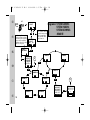
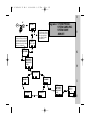
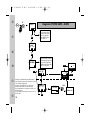
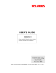
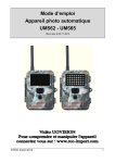
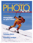
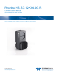
1
708 47 0018.A3 15 MS-1
01.04.2010
9:56 Uhr
Seite 1
MECABLITZ 15 MS-1 digital
Bedienungsanleitung
Gebruiksaanwijzing
Manuale istruzioni
Mode d’emploi
Operating instruction
Manual de instrucciones
708 47 0018.A3 15 MS-1
1
2
2.1
2.2
2.3
2.4
2.5
3
4
4.1
ķ
4.2
5
5.1
5.2
6
7
8
9
9.1
10
11
68
01.04.2010
9:56 Uhr
Safety instructions . . . . . . . . . . . . . . . . . . .69
Preparation . . . . . . . . . . . . . . . . . . . . . . .70
Power supply . . . . . . . . . . . . . . . . . . . . . .70
Insertion and replacement of batteries . . . . .71
Installation / Deinstallstion . . . . . . . . . . . .71
Switching the flash unit on and off . . . . . . .72
The infrared clamp . . . . . . . . . . . . . . . . . .72
Starting up for the first time . . . . . . . . . . .73
Camera-specific remote operation . . . . . . .73
General information on wireless
remote control . . . . . . . . . . . . . . . . . . . . .73
Setting remote channel and remote group . .75
Manual wireless slave mode . . . . . . . . . . .76
Learn function . . . . . . . . . . . . . . . . . . . . . .77
Slave mode . . . . . . . . . . . . . . . . . . . . . . . .79
Operation with synchronous cable . . . . . . .80
Operation of flash unit detached
from camera . . . . . . . . . . . . . . . . . . . . . . .81
Lighting OK in remote TTL mode . . . . . . . .81
Swivel reflectors . . . . . . . . . . . . . . . . . . . .81
Bounce diffuser . . . . . . . . . . . . . . . . . . . . .82
The AF auxiliary light . . . . . . . . . . . . . . . .82
Modelling light (ML) . . . . . . . . . . . . . . . . .83
Seite 68
12 Synchronisation on the 1st or 2nd shutter
curtain (REAR) . . . . . . . . . . . . . . . . . . . . . .84
13 Slow synchronisation (SLOW) . . . . . . . . . .84
13.1Using a tripod . . . . . . . . . . . . . . . . . . . . . .85
14 Care and maintenance . . . . . . . . . . . . . . .85
14.1Firmware update . . . . . . . . . . . . . . . . . . . .85
14.2 Reset . . . . . . . . . . . . . . . . . . . . . . . . . . . .85
14.3Conditioning the flash capacitor . . . . . . . . .86
15 Troubleshooting . . . . . . . . . . . . . . . . . . . .86
16 Technical data . . . . . . . . . . . . . . . . . . . . . .86
Diagram . . . . . . . . . . . . . . . . . . . . .134-137
Introduction
Thank you for choosing a Metz product.
We are delighted that you have become a Metz
customer.
Of course you can hardly wait to use your flash unit.
It is worthwhile to read the operating manual as it is
only in this way you can learn how to use the device
without difficulties.
☞
Please refer to the back cover at the end of the
manual.
708 47 0018.A3 15 MS-1
01.04.2010
1 Safety instructions
• The flash unit is exclusively designed
and authorised for use in photographic applications.
• Do not flash directly into eyes from
a close distance! Direct flashing into
the eyes of persons or animals can
cause damage to the retina and
severe disruption of the vision – up
to and including permanent blindness!
• The flash unit may in no event be
activated in the vicinity of inflammable gases or liquids (petroleum, solvents etc.). RISK OF EXPLOSIONS!
• Never use a flash unit to photograph car, bus, bicycle, motorbike
or train drivers while they are driving. Blinding the driver can lead to
an accident!
• Only use the power sources designated and authorised in the operating manual.
• Do not open the batteries or short
them!
• In no event the batteries be exposed
to high temperatures like direct sun-
9:56 Uhr
Seite 69
light, fire or similar!
• Remove the used batteries immediately from the device! Chemicals can
escape from used batteries (so-called “leaks”) resulting in damage to
the device!
• Batteries may not be recharged!
• Do not expose the flash unit to
water drops and splashes!
• Protect your flash unit from heat and
high air humidity! Do not keep it in
the glove compartment of your car.
• After repeated flashing, do not
touch the diffuser. Risk of burns!
• After a series of flashes with full
power and short intervals, a pause
of at least 3 minutes must be observed after each series of 20 flashes!
• When you activate the flash, there
should be no opaque material
directly in front of or on the reflector
cover (flash window). The intense
energy emissions can otherwise
lead to scorching or spotting of the
material and/or the reflector cover.
Do not dismantle the flash unit!
HIGH VOLTAGE!
ķ
69
708 47 0018.A3 15 MS-1
01.04.2010
9:56 Uhr
Seite 70
2 Preparation
Repairs should only be performed
by authorised service personnel.
• Do not touch the electrical contacts
of the flash unit.
• If the housing has been damaged in
such a way that internal components are exposed, the flash unit
may no longer be used. Remove the
batteries! Do not touch any internal
components. HIGH VOLTAGE!
• Do not use any toxic batteries or
rechargeable batteries!
2.1 Power supply
The flash unit can optionally be operated with:
• 2 alkali-manganese dry batteries
Type IEC LR03 (AAA / Micro),
maintenance-free power source for
moderate power requirements.
• 2 NC batteries Type IEC KR03
(AAA / Micro).
• 2 nickel metal hydride batteries
Type IEC HR03 (AAA / Micro), significantly higher capacity than
NC batteries and less harmful to the
environment than the NC batteries
as they are cadmium-free. They
offer very short flash sequence times
and economical operation as they
are rechargeable.
• 2 lithium batteries 1.5 V, Type IEC
FR03 (AAA / Micro), maintenancefree power source with high capacity and low self-discharge rate.
ķ
☞
70
The batteries/rechargeable batteries
are empty or used if the flash interval for flashes at full power rises
708 47 0018.A3 15 MS-1
01.04.2010
9:56 Uhr
• Close battery compartment cover and slide against the housing.
above 60 seconds. If you do not use
the flash unit for a prolonged period,
you should remove the batteries from
the unit.
2.3 Installation /Deinstallation
Carefully screw an adapter ring of the
appropriate size into the filter thread
of the objective.
2.2 Insertion and replacement of
batteries
• Turn off the flash unit via the main
switch .
• Slide the battery compartment cover
at the bottom of the flash unit
and fold it open.
• Insert the batteries in the accordance with the symbols on the inside of
the battery compartment cover.
When inserting batteries, ensure that
the polarity is correct and matches
the symbols in the battery compartment. Inserting the batteries in the
wrong direction can destroy the flash
unit! Always replace all batteries
simultaneously, and make sure that
batteries are the same brand and
have the same capacity. Flat or dead
batteries should not be disposed of
with ordinary household waste. Help
protect the environment, and dispose
of flat/dead batteries at the appropriate collection points.
Seite 71
☞
Recommendation: Only use internal
focusing objectives! Note, with external focusing objectives you must perform the focusing manually. The risk
of damage to the flash unit due to
the weight of the objective or of the
adjusting motor cannot be ruled out.
Press both the release buttons on
the flash unit, keep them pressed, and
at the same time insert the flash unit
up to the stopper on the adapter ring
of the objective.
When the release buttons are released, the flash unit is held on the
adapter ring by four snap-in clips.
☞
Make sure that the flash unit is securely locked in place on the adapter
ring. When the camera and the flash
unit are combined, always hold the
combination by the camera and
never by the flash unit.
☞
ķ
71
708 47 0018.A3 15 MS-1
01.04.2010
9:56 Uhr
The flash unit can be rotated (turned)
on the adapter ring.
Removal
Press both the release buttons on
the flash unit, keep them pressed, and
at the same time carefully pull the
flash unit off the adapter ring of the
objective.
2.4 Switching the flash unit on
and off
To switch-on, move the main switch to the “ON” position. To switch-off,
move the main switch to the left.
☞
ķ
72
If the flash unit is not required for a
longer period of time, it should
always be switched off by the main
switch and the batteries/rechargeable batteries should be removed from
the flash unit!
Seite 72
2.5 The infrared clamp
The camera’s own flash unit and the
use of mecablitz 15MS-1 digital
should not contribute to the lighting of
macropictures, so that no shadows
are caused by the housing of mecablitz 15MS-1 digital.
The camera’s own flash light can be
covered with the infrared clamp. The
infrared clamp allows the control
impulses through, but holds back the
flash light, which contributes to the
lighting.
Installation of the infrared clamp
Open the infrared clamp with your
fingers and slip it over the camera’s
own flash unit.
Slide down the infrared clamp with
rubber lips as far as possible over the
camera’s own flash unit and close it.
708 47 0018.A3 15 MS-1
01.04.2010
9:56 Uhr
Seite 73
3 Starting up for the first
time
4 Camera-specific remote
operation
When the flash unit is switched on for
the first time or when a “RESET” is
performed (see Chapterir 14.2), the
following display appears after the
main switch is activated:
This remote operating mode is only
possible if the camera supports remote operation with an integrated flash
or if an additional flash unit is mounted on the camera (e.g. Metz mecablitz 58AF-1) which supports remote
operation.
• Press the button S E L on the flash
unit. In the display appears:
• Now set the desired operating
mode:
- The camera specific remote control
(see Chapter 4)
- Manual wireless slave mode (see
Chapter 5)
- Learn function (see Chapter 5.1)
- Slave mode (see Chapter 5.2)
- Operation with a synchronous cable
(see Chapter 6)
15MS-1
V1.0
SELECT
SEL
4.1 General information on
wireless remote control
A remote system consists of a master
or controller flash unit in the camera
or an external master or controller
flash unit on the camera and one or
more slave flash units.
The slave flash unit is remotely controlled by the master or controller
flash unit.
A master flash unit contributes to the
lighting and at the same time controls
the slave flash units.
A controller flash unit only has control
functions.
The slave flash unit is assigned to one
of three possible groups (A, B or C –
ķ
73
708 47 0018.A3 15 MS-1
01.04.2010
9:56 Uhr
only with Canon, Nikon, Olympus).
Each group can in turn consists of one
or more slave flash units.
Four independent remote channels
(Channels 1-4) are available, so that
several remote systems in the same
space do not cause mutual disruption.
The setting “Channel ALL” controls all
slave flash units. Slave flash units that
belong to the same remote system
must be set to the same remote channel. The slave flash units must be able
to pick up the light from the master or
controller flash unit via integrated sensors for remote operation .
Adjustment of the flash unit
ķ
• Switch the flash units integrated in
the camera or external flash unit on
the camera in the Master or
Controller mode, see operating
manual of the camera or external
flash unit.
• Select an operating mode on the
camera that supports remote operation
74
Seite 74
• Slide the infrared clamp over the
camera’s own flash unit if it is to be
used as controller flash unit. Swivel
the external flash unit so that it cannot contribute to lighting.
15MS-1
V1.0
• Switch-on the flash unit with the
main switch .
• Keep the button “AF/SELECT” pressed down until the following
message appears in the display:
⊃
SELECT
SEL
MODELLING
LIGHT
OFF
ON
SEL
OK
SYSTEM
NIK REMOTE Ch ALL Gr A
S E L OK
SYSTEM
OLY REMOTE Ch ALL Gr A
S E L OK
• Press the button S E L on the flash
unit. In the display appears:
• Switch-on (ON) the “MODELLING
LIGHT” function with the button or switch it off (OFF).
• Press the button S E L on the flash
unit. The most recently used setting
appears in the display, e.g.:
• Press the button until the required version for the camera type
used appears in the display:
„CAN REMOTE“ (Canon) or
„NIK REMOTE“ (Nikon) or
„OLY REMOTE“ (Olympus) or
708 47 0018.A3 15 MS-1
01.04.2010
9:56 Uhr
Seite 75
„PEN REMOTE“ (Pentax) or
„SAM REMOTE“ (Samsung) or
„SON REMOTE“ (Sony)
• Press the OK button, thus the selected
remote mode is set, in the example
“OLY REMOTE” (Olympus). The ratio
of the reflectors is 1:1. Group A (only
with CAN, NIK and OLY) is automatically set if another group has not been
selected for a previous application.
• If the two reflectors should be set at
an unequal ratio (Ratio) then press
the button or to change the
ratio of both the reflectors.
GrA
OLY
1:1
GrA
OLY
8:1
The setting thus made will be automatically saved.
In the operating modes
“CAN REMOTE” or “NIK REMOTE”
and/or “OLY REMOTE”, various slave
channels and various slave groups can
be set when several slave flash units
are used (see Chapter 4.2).
In the operating modes
“PEN REMOTE” and/or
“SAM REMOTE” and/or
“SON REMOTE”, only different slave
☞
☞
channels can be set when several
slave flash units are used (see
Chapter 4.2 and operating manual
of the camera). The flash unit supports the wireless Sony remote
system in the “CTRL” and “CTRL + ”
modes, depending on the camera
system used. The “CTRL” and “CTRL +
” modes are automatically detected.
The slave flash units always work in
the “RMT” group. The set-up can
always be checked by pressing the
“AEL” key on the camera. The slave
flash unit must respond with a timedelayed flash.
4.2 Setting remote channel and
remote group
ķ
Four independent remote channels
(CHANNELS 1 to 4) are available, so
that several remote systems in the
same space does not cause mutual
disruption Master and/or controller
and slave flash units that belong to the
same remote system must be set to the
same remote channel.
In the case of Sony and Pentax
cameras “CHANNEL ALL” must be
☞
75
708 47 0018.A3 15 MS-1
☞
01.04.2010
9:56 Uhr
set if a fixed channel is not used in
the remote system.
In the case of “CHANNEL ALL”, all
set channels are activated.
In the remote operating modes,
groups can be set in addition to the
channels (CHANNEL) in order to control the desired slave flash unit of a
specific group.
The setting of groups (GROUP A, B,
C) is only possible in Canon, Nikon
and Olympus remote control modes.
Setting a channel (CHANNEL) and a
group (GROUP) in a camera-specific
remote system
ķ
• Keep the button “AF/SELECT” SELECT
pressed on the flash unit until the
following message appears in the
SEL ⊃
display:
MODELLING
LIGHT
OFF
ON
SEL
OK
SYSTEM
OLY REMOTE Ch ALL Gr A
S E L OK
76
• Press the button S E L on the flash
unit. In the display appears::
• Press the button S E L on the flash
unit. The most recently used setting
appears in the display, e.g.:
Seite 76
CHANNEL ALL
SEL
CHANNEL 3
SEL
SEL
• Press button and select the desired group (GROUP A, GROUP B,
GROUP C).
GROUP A
SEL
SYSTEM
OLY REMOTE Ch 3
Gr A
S E L OK
OLY Ch3 GrA
1:1
• Press button and select the
desired channel (CHANNEL ALL –
CHANNEL 1..4).
• Press button S E L , the selected
remote channel is set. In the display
appears:
GROUP A
• Press the button S E L on the flash
unit. In the display appears:
• Press button
group is set.
SEL
and the desired
• Press button OK , the selected remote channel and remote group are
set.
5 Manual wireless slave
mode
Even when cameras are used without
a camera-specific remote system,
wireless release of one or more slave
flash units is possible.
708 47 0018.A3 15 MS-1
01.04.2010
Several digital cameras fire one or
more measuring pre-flashes and/or
flashes for a fraction of a second
before the picture is taken in order to
reduce the „red-eye effect“. The measuring pre-flashes cannot usually be
deactivated on the camera.
When starting up the camera for the
first time, changing the camera or
RESET, select the “Learn function” (see
Chapter 5.1).
If the “Learn function” has already
been operated once and you continue
to use the same camera, select the
“Slave mode” (see 5.2).
5.1 Learn function
The “Learn function” enables individual automatic adjustment of the slave
flash unit to the flash technology of the
camera’s flash unit. In the process,
one or more pre-flashes, e.g. to reduce the “red-eye effect” of the camera
flash unit can be taken into account.
The slave flash unit is then fired to
coincide with the main flash that illuminates the actual picture.
9:56 Uhr
Seite 77
☞
If the camera’s own flash device provides for automatic focussing
AF measuring flashes, then due to
the system characteristics no learn
operation is possible. If possible, use
another camera mode or change to
manual focussing.
Adjustment of the flash unit
• Activate camera flash unit. If required, activate the pre-flash function
on the camera to reduce the
“red-eye effect”.
• Slide infrared clamp over the
camera’s own flash unit, if it is to be
used as controller flash unit. Swivel
external flash unit so that it cannot
contribute to lighting.
• Switch-on the flash unit with the
main switch .
ķ
15MS-1
• Keep the button “AF/SELECT” pressed until the following message
appears in the display:
• Press the button S E L on the flash
unit. In the display appears:
V1.0
SELECT
SEL
⊃
MODELLING
LIGHT
OFF
ON
SEL
OK
77
708 47 0018.A3 15 MS-1
SYSTEM
NIK REMOTE Ch ALL Gr A
S E L OK
SYSTEM
S L AV E
SEL
LEARN
NO
NO
YES
SEL
LEARN
OK
OK
YES
SEL
OK
01.04.2010
9:56 Uhr
• Press the button S E L on the flash
unit. The most recently used setting
appears in the display, e.g.:
• Press the button until “SYSTEM
SLAVE” appears in the display.
LEARN
78
OK
SL
P/R
SL
Ratio
4:1
• Switch-on (YES) the “LEARN” function with the button.
SL
• Press the release button on the
camera so that the camera’s own
flash unit is activated.
If a light impulse has been received
by the mecablitz 15MS-1 digital, the
bar display stops filling. In the
display, “LEARN OK” appears and a
red light in the „AF-/SELECT“ button
lights up briefly as confirmation.
Ratio
1:1
• Press button S E L drücken. In the
display appears:
• Press OK button. In the display
TA K E A
PICTURE
appears:
The flash unit waits for a flash light
⊃
from the camera’s own flash unit.
The bar display continually fills as
long as no light impulse is received
from the camera’s own flash unit.
ķ
Seite 78
P/R
Power
1/1
SL
P/R
Power
1/4
P/R
The mecablitz 15MS-1 digital has
now learnt to recognise the flash
light of the camera flash unit. In the
display appears:
• If both the reflectors should be set to
an unequal ratio (Ratio) then press
the button or to change the
ratio of both the reflectors.
• If you wish to use partial lighting,
then press the button P / R
Following display appears:
• To set partial lighting, press the buttons or and thus change the
value. In the display appears, for
example.
The setting thus made will be automatically saved
☞
If the “Learn function” has already
been operated once, these settings
are retained until the learn function
is used for the next time.
☞
If the setting to reduce the “red-eye
effect” is changed, the learn function
must be repeated.
708 47 0018.A3 15 MS-1
01.04.2010
9:56 Uhr
Seite 79
5.2 Slave mode
• Press the button S E L on the flash
unit. The most recently used setting
appears in the display, e.g.:
“Slave mode” reflects the setting that
has been learnt in the “Learn function”. This function is retained until a
“Learn function” or a “RESET” is performed again.
• Press the button until “SYSTEM
SLAVE” appears in the display.
• Press the OK button and the SLAVE
mode is set with a ratio of 1:1 between both the reflectors and full
lighting power (Power) 1/1.
Following display appears:
Adjustment of the flash unit
• Activate the camera flash unit.
• Slide the infrared clamp over the
camera’s own flash unit if it is to be
used as controller flash unit. Swivel
external flash unit so that it cannot
contribute to lighting.
• Switch-on flash unit with the main
switch .
• If both reflectors should be set at an
unequal ratio (Ratio) then press the
button or to change the ratio.
The ratio can be adjusted in steps. In
the display appears, for example
15MS-1
• Keep the button “AF/SELECT” on
the flash unit pressed until the following message appears in the
display:
SEL
• Press the button
on the flash
unit. In the display appears:
V1.0
• If you wish to use partial lighting,
then press the button P / R .
Following display appears:
SYSTEM
NIK REMOTE Ch ALL Gr A
S E L OK
SYSTEM
S L AV E
SEL
SL
OK
Ratio
1:1
P/R
SL
Ratio
4:1
SL
P/R
Power
1/1
P/R
SELECT
SEL
⊃
MODELLING
LIGHT
OFF
ON
SEL
OK
• To set partial lighting, press the buttons or and thus change the
value. In the display appears, for
example.
SL
Power
1/4
P/R
The setting thus made will be automatically saved.
79
ķ
708 47 0018.A3 15 MS-1
☞
01.04.2010
9:56 Uhr
For Remote Control mode , the
slave flash unit must be able to register the light from the camera flash
unit immediately and without restriction so that it is fired! The operating
range of the arrangement depends
on the intensity of the light impulse
of the camera flash unit, the reflection characteristics of the object and
ambient lighting.
Please note that the operating range
is reduced outside and when the
ambient light is bright. Avoid exposing the flash unit light sensors to
direct sunlight!
Seite 80
Adjustment of the flash unit
• Select a manual operating mode on
the camera.
15MS-1
• Keep the button “AF/SELECT” on
the flash unit pressed until the following message appears in the
⊃
display:
SELECT
SEL
MODELLING
LIGHT
OFF
ON
SEL
SYSTEM
ķ
V1.0
OK
6 Operation with
synchronous cable
S L AV E
The flash unit can be operated with a
synchronous cable 15-50. For this,
connect the synchronous socket of the
camera with the synchronous socket
of the flash unit.
SYSTEM
SYNC-CORD SEL
OK
OK
SYNC
R atio
1:1
80
• Switch-on flash unit with the main
switch .
P/R
• Press the button S E L on the flash
unit. In the display appears:
• Press the button S E L on the flash
unit. The most recently used setting
appears in the display, e.g.:
• Press the button suntil
“SYNC-CORD” appears in the
display.
• Press the OK button and the
“SYNC-CORD“ mode is set with a
ratio of 1:1 between both the reflectors and full lighting power (Power)
1/1. The following display appears:
708 47 0018.A3 15 MS-1
01.04.2010
• If both the reflectors should be set at
an unequal ratio (Ratio) then press
the buttons to change the
ratio. The ratio can be adjusted in
steps. In the display appears, for
example.
• If you wish to use partial lighting,
then press the button P / R .
Following display appears:
• To set partial lighting, press the buttons or and thus change the
value. In the display appears, for
example.
The setting thus made will be automatically saved.
7 Operation of flash unit
detached from camera
The flash unit can be detached from
the camera and setup on the base unit
or can be fixed to a tripod with the
tripod thread .
For detached setup, please ensure that
the sensors for remote operation can receive the light from the camera
flash unit.
9:56 Uhr
Seite 81
8 Lighting OK in
remote TTL mode
SYNC
R atio
1:8
P/R
SL
Power
1/1
P/R
SYNC
P ower
1/4
P/R
In camera-specific remote–TTL mode,
the button “AF/SELECT” also serves as lighting OK display. If the
object has been sufficiently illuminated, then the red “AF/SELECT” button lights up for approx.
3 seconds.
If the object has been over illuminated, then the red “AF/SELECT” button blinks for approx. 3 seconds.
Change the ISO setting or the aperture and try the illumination again.
If the object has been insufficiently
illuminated, then the red “AF/SELECT”
button does not light up.
Change the ISO setting or the aperture and try the illumination again.
ķ
9 Swivel reflectors
Both the reflectors can be swivelled
by 10° and 20°. To swivel the reflectors, press the reflector swivel lever forwards in steps. In the first indexed
position, the reflector is swivelled
81
708 47 0018.A3 15 MS-1
01.04.2010
9:56 Uhr
Seite 82
inwards by 10°, at the second position by 20°.
☞
The working distance is the distance
between the object and the front
edge of the flash unit.
As a guideline, we recommend :
• Working distance of approx.
2-10cm: Swivel reflectors by 20°
and set the bounce diffuser (see 9.1)
in front of reflectors.
At distances over 10 cm, the reflectors
can be swivelled to a greater or lesser
extent to achieve a centre weighted
average or a balanced illumination.
ķ
9.1 Bounce diffuser
The bounce diffuser is required for
illuminating the objects in close proximity at distances less than 10 cm.
Installation of bounce diffuser
Position the bounce diffuser asymmetrically over the flash unit so that
the reflectors and the AF auxiliary
light are covered.
Press the bounce diffuser against
the housing of the flash unit until it
82
audibly snaps into place.
Turn the bounce diffuser so that
the notch of the marking tab aligns
with the marking point on the flash
unit housing.
Removal of bounce diffuser
Gently bend up one of the tabs on
the bounce diffuser and release it.
Take off the bounce diffuser.
☞
Do not lift and remove the bounce
diffuser at the marking tab .
10 The AF auxiliary light
The flash unit is equipped with an AF
auxiliary light which illuminates the
object in dark conditions so that the
camera can focus clearly on the
object or it can be used as illumination for manual focusing.
The AF auxiliary light is switched on
with button and lights up for
around 10 seconds. If a picture is
taken, the AF auxiliary light switches
off immediately and thus does not
contribute to the lighting.
708 47 0018.A3 15 MS-1
01.04.2010
9:56 Uhr
Seite 83
11 Modelling Light (ML)
• As a confirmation that the
“Modelling Light” is switched on,
the manual release button blinks.
The modelling light (setting light) is a
high frequency, stroboscopic flash
light. The effect of a quasi continuous
light is created for a duration of
approx. 2 seconds. The setting light
can be used to assess the light distribution and shadow formation before
taking a picture.
Triggering modelling light
Press the manual release button to
trigger the modelling light.
The modelling light is generated
according to the possibly set ratio of
the reflectors (Ratio).
Activating the modelling light
• Switch-on flash unit with the main
switch .
Deactivating modelling light
15MS-1
• Keep the button “AF/SELECT” pressed until the following message
appears in the display:
• Press the button S E L on the flash
unit. In the display appears:
• Switch-on (ON) the “MODELLING
LIGHT” function with the button • Press OK button and the “Modelling
Light” function is switched to the
preset operating mode.
V1.0
SELECT
SEL
⊃
MODELLING
LIGHT
OFF
ON
SEL
OK
MODELLING
LIGHT
OFF
ON
SEL
OK
☛
• Keep the button “AF/SELECT” pressed until the following message
appears in the display:
• Press the button S E L on the flash
unit. In the display appears:
• Switch-off (OFF) the “MODELLING
LIGHT” function with the button .
SELECT
SEL
⊃
MODELLING
LIGHT
OFF
ON
SEL
OK
MODELLING
LIGHT
OFF
ON
SEL
OK
• Press the
button and the modelling light function is deactivated.
OK
83
ķ
708 47 0018.A3 15 MS-1
01.04.2010
9:56 Uhr
12 Synchronisation on the
1st or 2nd shutter
curtain (REAR)
Some cameras support synchronisation with the 2nd shutter curtain
(REAR). Thus, the flash unit is not fired
until the shutter has closed. This is
especially advantageous when lighting with slow shutter speeds (>
1/30s) and moving objects with their
own light sources since moving light
sources leave behind a trail of light,
instead of in the front as with synchronisation on the 1st shutter curtain. This
results in a more “natural” reproduction of the situation when the picture
was taken for moving light sources.
Depending on the operating mode,
the camera triggers slower shutter
speeds than the flash sync speed.
In some cameras, in certain operating
modes (e.g. with certain Vari and/or
Object programs or with pre-flash
function against the “red-eye effect”),
REAR operating mode is not possible.
The REAR operating mode cannot be
selected in this case or is automatical-
ķ
84
Seite 84
ly deleted or not performed (see
Camera user manual). The REAR operating mode is set on the camera (see
Camera user manual). No settings are
necessary on the flash unit, nor is there any display for this mode.
13 Slow synchronisation
(SLOW)
SLOW lighting brings the picture
background into stronger focus with
weak ambient lighting. This is achieved by the camera shutter speeds that
are adjusted to the ambient light.
Thus, automatic shutter speeds are
automatically triggered that are longer than the flash sync speed (e.g.
shutter speeds up to 30s). Slow synchronisation is activated automatically
on some camera models in connection
with certain camera programs (e.g., a
night shot program, etc.), or it can be
set on the camera (see the camera’s
operating instructions). No settings
are necessary on the flash unit, nor is
there any display for this mode.
01.04.2010
Slow synchronisation SLOW is set on
the camera (see camera’s operating
instructions)! Use a tripod when
shooting with slow shutter speeds to
avoid blurred images!
13.1 Using a tripod
The tripod thread of the flash unit
may only be used for setting up the
flash unit as a slave unit without
camera.
If the camera has a mecablitz 15MS-1
digital attached to it, only then the tripod thread on the camera may be
used to mount it on a tripod.
14 Care and maintenance
Remove any dirt and dust with a soft,
dry cloth. Do not use any cleaning
agents – plastic components could be
damaged.
14.1 Firmware update
The firmware for the flash unit can be
updated via the USB socket and
conform to the functions of future
cameras (firmware update).
9:56 Uhr
☞
Seite 85
☞
You can find out more by visiting the
Metz homepage: www.metz.de
14.2 Reset
The flash unit can be reset to factory
settings.
Resetting flash unit to factory settings
(RESET)
• Switch-on the flash unit with the
main switch .
• Keep the black button on the flash
unit on the left pressed until
“FACTORY SETTINGS” appears in
the display:
• Press the button and switch-on
(YES) “FACTORY SETTINGS”.
• Confirm “FACTORY SETTINGS” by
pressing the OK button.
The display flashes: The flash unit is
reset to the state when it was delivered.
• When the flash unit has been reset
to the state when it was delivered,
the following message appears as
confirmation in display:
☛
708 47 0018.A3 15 MS-1
FA C T O R Y
SETTINGS
NO
YES
OK
FA C T O R Y
SETTINGS
NO
YES
OK
RESET
SELECT
SEL
85
ķ
708 47 0018.A3 15 MS-1
☞
01.04.2010
9:56 Uhr
This will not affect firmware updates
for the flash unit!
normally when switched on. If this is
not the case, then contact your dealer.
14.3 Conditioning the
flash capacitor
16 Technical data
The flash capacitor built into the flash
unit undergoes a physical change
when the device has not been used for
a long time.
For this reason it is necessary to
switch the device every three months
for approx. 10 mins. The power supplies must deliver enough power so
that flash standby lights up no later
than 1 min after switching on.
ķ
15 Troubleshooting
☞
86
Seite 86
If for example, inappropriate messages appear in the display of the flash
unit or the flash unit does not operate as it should, switch the flash unit
off for approx. 10 seconds with the
main switch .
Replace the batteries or rechargeable
batteries with new batteries or fully
recharged batteries!
The flash unit should now operate
Maximum guide number for ISO
100; 50 mm
In metric system: 15
In feet:
49
Manual flash operating modes:
Manual flash mode via sync socket
Remote flash operating modes:
• Canon E-TTL-Remote.
• Nikon i-TTL-Remote.
• Olympus/Panasonic
FourThirds-System TTL Remote.
• Pentax/Samsung
P–TTL–Remote–System.
• Sony-TTL-Remote
Slave flash operating modes:
• Slave mode with pre-flash
suppression via Learn function.
708 47 0018.A3 15 MS-1
01.04.2010
Manual partial lighting:
P1/1 to P1/64
Colour temperature:
Approx. 5.600 K
Synchronisation:
Low voltage – IGBT – ignition
Flash counts:
With NiCd batteries (250 mAh)
approx. 50
With high performance alkali-manganese batteries approx. 140
With NiMH rechargeable batteries
(1000 mAh) approx. 200
With lithium batteries approx. 250.
(at full light power in each case)
Recycling times:
Depending on the light output:
approx. 0.3-5 s.
Illumination:
50 mm (small picture format)
9:56 Uhr
Seite 87
Swivel ranges and indexed positions
of the reflectors:
Horizontal: 0° 10° 20°
Dimensions in mm (W x H x D):
Approx.. 133 x 144 x 38
Weight:
Approx. 190 g without power supply
Scope of delivery:
Flash unit , bounce diffuser,
infrared clamp, adapter ring 52mm,
adapter ring 55mm, adapter ring
58mm, belt pouch, operating manual.
Special accessories:
• Adapter ring 15-62
(order no.: 000015622)
Adapter ring M62x0,75mm
• Adapter ring 15-67
(order no.: 000015673)
Adapter ring M67x0,75mm
• Adapter ring 15-72
(order no.: 000015673)
Adapter ring M72x0,75mm
• Synchronkabel 15-50
(order no.: 000015501
ķ
87
708 47 0018.A3 15 MS-1
01.04.2010
9:56 Uhr
Battery disposal
Germany: As a consumer, you are
legally obliged to return used batteries.
You will find this symbol on batteries
that contain harmful substances:
Pb = Battery contains lead
Cd = Battery contains cadmium
Hg = Battery contains mercury
Li = Battery contains lithium
ķ
88
Seite 88
Your Metz product was developed
and manufactured with high-quality
materials and components which can
be recycled and/or re-used.
This symbol indicates that electrical
and electronic equipment must be
disposed of separately from normal
garbage at the end of its operational
lifetime.
Please dispose of this product by bringing it to your local collection point or
recycling centre for such equipment.
This will help to protect the environment in which we all live.
708 47 0018.A3 15 MS-1
Seite 134
SEL
oder zuletzt eingestellte Anwendung
ou dernière utilisation configurée
of de laatst ingestelde toepassing
or most recently set application
o all’utilizzo impostato per ultimo
o último uso configurado
SEL
⊃
zurück zur letzten Anwendung
Retour à la dernière utilisation
Terug naar de laatste toepassing
Return to last application
Indietro all’ultimo utilizzo
volver al último uso
⊃
MODELLING
LIGHT
OFF
ON
SYSTEM
SYNC-CORD ń
SEL
OK
SEL
OK
SYSTEM
CAN REMOTE N I K REMOTE OLY REMOTE GROUP A
A
GROUP B
SEL
OK
SEL
GROUP C
CHANNEL ALL
SEL
SEL
CHANNEL 4
ƴ
CHANNEL 1
SEL
CHANNEL 3
134
SEL
SEL
SEL
SEL
Ch ALL Gr A
S E L OK
ķ
į
Diagramm: SYSTEM CANONSYSTEM NIKONSYSTEM OLYMPUS-REMOTE
SELECT
SELECT
3 Sek.
ĸ
9:56 Uhr
AF
Start
☛
Ķ
01.04.2010
CHANNEL 2
SEL
SEL
A
SEL
SYSTEM
CAN REMOTE N I K REMOTE OLY REMOTE Ch ALL Gr C
S E L OK
OK
CAN Ch1 GrC
N I K Ch1 GrC
O L Y Ch1 GrC
1:1
708 47 0018.A3 15 MS-1
01.04.2010
9:56 Uhr
Seite 135
Ķ
AF
Start
☛
SELECT
SELECT
SEL
3 Sek.
SEL
oder zuletzt eingestellte Anwendung
ou dernière utilisation configurée
of de laatst ingestelde toepassing
or most recently set application
o all’utilizzo impostato per ultimo
o último uso configurado
⊃
MODELLING
LIGHT
OFF
ON
SYSTEM
SYNC-CORD ⊃
SEL
zurück zur letzten Anwendung
Retour à la dernière utilisation
Terug naar de laatste toepassing
Return to last application
Indietro all’ultimo utilizzo
volver al último uso
Diagramm: SYSTEM PENTAXSYSTEM SAMSUNGSYSTEM SONY-REMOTE
ĸ
OK
ń
SEL
OK
SYSTEM
PEN REMOTE SAM REMOTE SON REMOTE Ch ALL
SEL
ķ
OK
SEL
CHANNEL ALL
SEL
CHANNEL 4
SEL
SEL
SEL
CHANNEL 3
SEL
ƴ
CHANNEL 1
CHANNEL 2
SEL
SYSTEM
PEN REMOTE SAM REMOTE SON REMOTE Ch ALL
SEL
OK
OK
PEN Ch1
SAM Ch1
SON Ch1
1:1
135
į
708 47 0018.A3 15 MS-1
SEL
Seite 136
Diagramm: SYSTEM SLAVE + LEARN
SELECT
SELECT
3 Sek.
ĸ
9:56 Uhr
AF
Start
☛
Ķ
01.04.2010
⊃
zurück zur letzten Anwendung
Retour à la dernière utilisation
Terug naar de laatste toepassing
Return to last application
Indietro all’ultimo utilizzo
volver al último uso
⊃
SEL
MODELLING
LIGHT
OFF
ON
ń
SEL
OK
SEL
oder zuletzt eingestellte Anwendung
ou dernière utilisation configurée
of de laatst ingestelde toepassing
or most recently set application
o all’utilizzo impostato per ultimo
o último uso configurado
SYSTEM
SYNC-CORD ķ
OK
S L AV E
SEL
OK
SL
į
Lernfunktion nur bei Erstinbetriebnahme oder nach Kamerawechsel
Fonction d’apprentissage uniquement lors de la première mise en service
ou après un changement d’appareil photo
Leerfunctie bij eerste ingebruikneming of na een andere camera
Learn function only for first time setup or after camera change
Funzione di apprendimento solo per la prima messa in funzione o per il
cambio della fotocamera
Función de aprendizaje únicamente en primera puesta en servicio o tras
cambio de cámara
136
P/R
R atio
1:1
OK
ƴ
P ower
1/4
SYSTEM
SL
P/R
P/R
P/R
SEL
LEARN
NO
YES
SEL
OK
OK
SEL
klick
TA K E A
PICTURE
⊃
LEARN
OK
708 47 0018.A3 15 MS-1
01.04.2010
9:56 Uhr
AF
Start
☛
SELECT
SEL
Ķ
Diagramm: SYSTEM SYNC-CORD
SELECT
3 Sek.
Seite 137
⊃
zurück zur letzten Anwendung
Retour à la dernière utilisation
Terug naar de laatste toepassing
Return to last application
Indietro all’ultimo utilizzo
volver al último uso
⊃
SEL
ĸ
MODELLING
LIGHT
OFF
ON
SEL
OK
ń
SEL
SYSTEM
S L AV E
SEL
oder zuletzt eingestellte Anwendung
ou dernière utilisation configurée
of de laatst ingestelde toepassing
or most recently set application
o all’utilizzo impostato per ultimo
o último uso configurado
OK
ķ
SYNCH P ower
SYSTEM
SYNC-CORD P/R
1/4
OK
SYNCH
P/R
R atio
1:1
OK
P/R
ƴ
P/R
137
į
708 47 0018.A3 15 MS-1
01.04.2010
9:56 Uhr
Seite 138
Garantiebestimmungen Bundesrepublik Deutschland
1. Die Garantiebestimmungen gelten ausschließlich für
Käufe in der Bundesrepublik Deutschland.
2. Im Ausland gelten die Gewährleistungsregelungen des
jeweiligen Landes bzw. die Garantieregelungen des
Verkäufers.
3. Die nachfolgenden Bestimmungen haben nur für
den privaten Gebrauch Gültigkeit.
4. Die Garantiezeit - 24 Monate - beginnt mit dem
Abschluss des Kaufvertrages bzw. mit dem Tag der
Auslieferung des Gerätes an den Käufer
(Endverbraucher).
5. Garantieansprüche können nur unter Nachweis des
Kaufdatums durch Vorlage des vom Verkäufer maschinell erstellten Original-Kaufbeleges geltend gemacht
werden.
6. Beanstandete Geräte bitten wir zusammen mit dem
Kaufbeleg entweder über den Fachhändler oder direkt
an die Firma Metz-Werke GmbH & Co KG Zentralkundendienst - Ohmstrasse 55, 90513 Zirndorf,
transportsicher verpackt unter genauer Schilderung der
Beanstandung einzusenden. Sie können unter den gleichen Bedingungen auch an die autorisierten
Kundendienststellen der Firma Metz-Werke GmbH & Co
KG eingesandt werden. Hin- und Rücksendung erfolgen
auf Gefahr des Käufers.
7. Die Garantie besteht darin, dass Geräte, die infolge
eines anerkannten Fabrikations- oder Materialfehlers
138
defekt geworden sind, kostenlos repariert oder, soweit
eine Reparatur unverhältnismäßig ist, ausgetauscht werden. Eine weitergehende Haftung, insbesondere für
Schäden, die nicht am Gerät selbst entstanden sind, ist
ausgeschlossen. Dies gilt nicht, soweit im Falle des
Vorsatzes oder der groben Fahrlässigkeit zwingend
gehaftet wird.
Garantieleistungen bewirken weder eine Verlängerung
der Garantiezeit, noch wird für die ersetzten oder nachgebesserten Teile eine neue Garantiezeit begründet.
8. Unsachgemäße Behandlung und Eingriffe durch den
Käufer oder Dritte schließen die Garantieverpflichtungen
sowie alle weiteren Ansprüche aus.
Ausgenommen von der Garantie sind ferner Schäden
oder Fehler, die durch Nichtbeachtung der
Gebrauchsanleitung, mechanische Beschädigung, ausgelaufene Batterien oder durch höhere Gewalt, Wasser,
Blitz etc. entstanden sind. Ferner sind Verschleiß,
Verbrauch sowie übermäßige Nutzung von der Garantie
ausgenommen. Hiervon sind vor allem folgende Teile
betroffen: Blitzröhre, fest eingebaute Akkus, Kontakte,
Verbindungskabel.
9. Durch diese Garantiebestimmungen werden die
Gewährleistungsansprüche des Käufers gegenüber dem
Verkäufer nicht berührt.
Metz-Werke GmbH & Co KG
708 47 0018.A3 15 MS-1
01.04.2010
Hinweis:
Ķ
Im Rahmen des CE-Zeichens wurde
bei der EMV-Prüfung die korrekte
Belichtung ausgewertet
Remarque:
ĸ
L’exposition correcte a été évaluée
lors des essais de CEM dans le
cadre de la certification CE.
9:56 Uhr
Seite 139
Opmerking:
ń
In het kader de CE-markering werd
bij de EMV-test de correcte belichting bepaald.
Note:
ķ
Within the framework of the CE approval symbol, correct exposure
was evaluated in the course of the
electromagnetic compatibility test.
Avvertenza:
ƴ
Nell’ambito delle prove EMV per il
segno CE è stata valutata la corretta esposizione.
Atención:
į
El símbolo CE significa una valoración da exposición correcta con la
prueba EMV (prueba de tolerancia
electromagnética).
Technische Änderungen und Irrtümer vorbehalten !
Sous réserve de modifications et d’erreus !
Onder voorbehoudvan wijzigingen en vergissingen !
Errors excepted. Subject to changes !
Riserva di modifiche e disponibilità di fornitura.
Con reserva de modificaciones y posibilidades de entrega.
708 47 0018.A3 15 MS-1
01.04.2010
9:56 Uhr
Seite 140
Metz - Werke GmbH & Co KG • Postfach 1267 • D-90506 Zirndorf • [email protected] • www.metz.de
Consumer electronics
Photoelectronics
Plastics technology
708 47 0018.A3
Metz - always first class.
Ķĸńķƴį