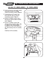
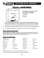
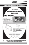
1
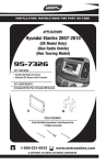
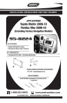
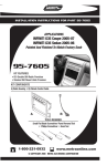
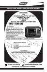
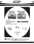
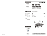
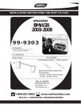
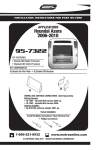
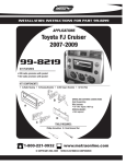
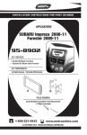
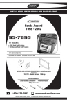
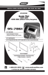
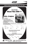
INSTALLATION INSTRUCTIONS FOR PART 95-7868B
APPLICATIONS
ACURA
CL 2001-2003
TL 1999-2003
95-7868B
KIT FEATURES
• Double DIN Radio Provision
• Stacked ISO Mount Units Provision
KIT COMPONENTS
• A) Double DIN Radio Housing • B) Double DIN Brackets • C) Double DIN Trim Plate
• D) (2) Phillips Screws
D
B
A
C
TOOLS REQUIRED:
• Phillips Screwdriver • Socket Set
1-800-221-0932
www.metraonline.com
© COPYRIGHT 2009 METRA ELECTRONICS CORPORATION
95-7868B
TABLE OF CONTENTS
Dash Disassembly
- ACURA CL 2001-2003/TL 1999-2003 . . . . . . . . . . . . . . . . . . 1,2
Kit Assembly
- Double DIN Radio Provision/ Stacked ISO Mount Units Provision . . . . . 3
Final Assembly . . . . . . . . . . . . . . . . . . . . . . . . . . . . . . . . . . . . . . . . . . . 4
*Note:
Refer also to the instructions included with the aftermarket radio.
KNOWLEDGE IS POWER
Enhance your installation and fabrication skills by
enrolling in the most recognized and respected
mobile electronics school in our industry.
Log onto www.installerinstitute.com or call
800-354-6782 for more information and take steps
toward a better tomorrow.
95-7868B DASH DISASSEMBLY
ACURA CL 2001-2003 / TL 1999-2003
A
1 Disconnect the negative battery terminal to prevent an accidental short
circuit.
2 Unclip and remove wood trim from
both sides of center console.
(Figure A)
3 Open armrest and remove (2) Phillips
screws inside and (2) Phillips at front
edge of rear of console and pull
rearward. (Figure B)
4 Open fuse access and remove (1)
Phillips screw then unclip and remove
panel below steering column.
(Figure C)
B
5 Remove (3) Phillips screws per center
console side panel and unclip and
remove panels (driver’s side and
passenger side). (Figure D)
Continued on page 2.
C
D
1
95-7868B DASH DISASSEMBLY
ACURA CL 2001-2003 / TL 1999-2003
E
6 Unclip and remove seat heater switch
trim panel to access (2) Phillips
screws and remove screws. (Figure E)
7 Unclip bottom of A/C control trim
panel and pull away (no need to
completely remove). (Figure F)
8 Remove (3) Phillips screws and (1)
push pin per side of radio to remove
radio. (Figure G)
9 Remove (2) Phillips screws from
storage pocket assembly above radio
to separate. (The storage pocket
assembly will have to be attached to
the radio housing in the kit assembly
next)
F
Continue to kit assembly.
G
2
95-7868B KIT ASSEMBLY
DOUBLE DIN RADIO PROVISION/
STACKED ISO MOUNT RADIO PROVISION
*Note: Refer also to the instructions included with the aftermarket radio.
1 Snap the Double DIN brackets to the
inside edge of the Double DIN radio
housing. (Figure A)
A
2 Slide the Double DIN head unit or
stacked ISO head units into the
bracket/radio housing assembly and
secure the Double DIN head unit or
stacked ISO head units to the
assembly using the screws supplied
with the radio. (Figure B)
3 Align holes in top of radio housing
with the guide pins on the bottom of
the storage pocket assembly and
secure the pocket assembly to the
legs with the (2) screws provided.
(Figure C)
B
4 Attach the double DIN trimplate to the
double DIN radio housing/bracket
assembly. (Figure C)
Continue to final assembly.
C
3
95-7868B FINAL ASSEMBLY
FINAL ASSEMBLY
A
(A) Strip wire ends back 1/2"
B
B) Twist ends together
C) Solder
D) Tape
C
D
1
Locate the factory wiring harness in the dash. Metra recommends using the
proper mating adapter and making connections as shown. (Isolate and individually tape off the ends of any unused wires to prevent electrical short circuit.)
2
Re-connect the negative battery terminal and test the unit for proper operation.
3
Reassemble radio and dash assemblies in reverse order of disassembly.
FINAL WIRING CONNECTIONS
Make wiring connections using the EIA color code chart shown below and the instructions included with the
head unit. Metra recommends making connections as shown below; Strip, Splice, Solder, Tape. Isolate and
individually tape off ends of any unused wires to prevent electrical short circuit.
METRA / EIA WIRING CODE
12V Ignition / Acc. . . . . . . . . . Red
Right Front (+) . . . . . . . . . . . . Gray
12V Batt / Memory. . . . . . . . . Yellow
Right Front (-). . . . . . . . . . . . . Gray/ Black
Ground. . . . . . . . . . . . . . . . . . Black*
Left Front (+) . . . . . . . . . . . . . White
Power Antenna. . . . . . . . . . . . Blue
Left Front (-). . . . . . . . . . . . . . White / Black
Amp Turn-On . . . . . . . . . . . . . Blue / White
Right Rear (+) . . . . . . . . . . . . Violet
Amp Ground. . . . . . . . . . . . . . Black / White
Right Rear (-) . . . . . . . . . . . . . Violet / Black
Illumination . . . . . . . . . . . . . . Orange
Left Rear (+) . . . . . . . . . . . . . Green
Dimmer . . . . . . . . . . . . . . . . . Orange / White
Left Rear (-) . . . . . . . . . . . . . . Green / Black
*NOTE: When a Black wire is not present, ground radio to vehicle chassis.
All colors may not be present on all leads due to manufacturer’s specifications.
4
95-7868B
NOTES
5
95-7868B INSTRUCTIONS
1-800-221-0932
REV. 03/02/09
www.metraonline.com
© COPYRIGHT 2009 METRA ELECTRONICS CORPORATION
INST95-7868B