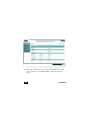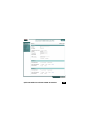
1
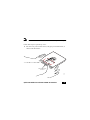
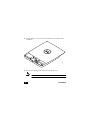
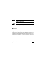
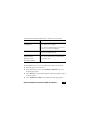
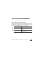
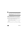
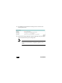
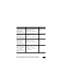
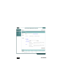
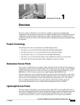
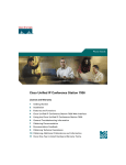
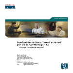
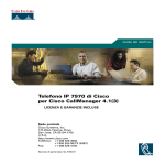
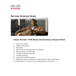
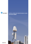
Read This First
You should review this table and the instructions for opening the top cover.
The table contains important information you need to know so you can
successfully configure your access point.
Setting
Default
Login
Cisco (case sensitive)
Password
Cisco (case sensitive)
IP address
Determined by DHCP server. See
the “Obtaining an IP Address” on
page 16 for additional information.
Service Set Identifier (SSID)
None assigned
Status LED
Status Description
Blue
Normal operating condition, and at
least one client device is associated
with the access point.
Light green
Normal operating condition, no
client devices are associated.
Amber or red
Error condition. See the “Checking
the Access Point LEDs” section on
page 38.
Quick Start Guide Cisco Aironet 1130AG Access Point
1
Radio and IP Address Configuration
The access point ships with its radio disabled.You must enable them when
you configure the access point for the first time. Also, the access point no
longer is assigned an IP address. It is configured to obtain an IP address using
a DHCP server. If your network does not use a DHCP server, you must
connect to the access point’s console port and assign a static IP address (See
the “Assigning an IP Address Using the CLI” section on page 17.
How to Open the Top Cover
The top cover provides access to the cable and power connections.
Caution
Do not open the access point top cover as you would a hatch or
door. You could damage the cover by doing so. An instruction
label is attached to the access point. Take time to read the label
before you open the access point cover.
When you have familiarized yourself with the opening procedure, we
recommend that you remove the label, putting it in a safe place, such as inside
the cover of this guide.
2
78-15955-02
Note
Status LED indications are not visible when the top cover is open.
Follow these steps to open the top cover:
1.
Put the access point on a flat surface, and grasp it with both hands, as
shown in this illustration.
121061
Cable access notch
and arrow
Quick Start Guide Cisco Aironet 1130AG Access Point
3
Gently push the cover away from you until it stops, as shown in this
illustration.
3.
Remove the opening instruction label from the top cover.
121423
2.
Note
4
We recommend that you save the label for reference.
78-15955-02
Safety Information
The FCC, with its action in ET Docket 96-8, has adopted a safety standard for
human exposure to RF electromagnetic energy emitted by FCC-certified
equipment. When used with approved Cisco Aironet antennas, Cisco Aironet
products meet the uncontrolled environmental limits found in OET-65 and
ANSI C95.1, 1991. Proper operation of this radio device according to the
instructions in this document and the installation and configuration guide will
result in user exposure substantially below the FCC recommended limits.
•
Do not hold any component containing a radio such that the antenna is
very close to or touching any exposed parts of the body, especially the
face or eyes, while transmitting.
•
The use of wireless devices in hazardous locations is limited to the
constraints posed by the safety directors of such environments.
Warnings
Translated versions of these safety warnings are provided in the Cisco Aironet
1130AG Series Access Point Hardware Installation Guide.
Quick Start Guide Cisco Aironet 1130AG Access Point
5
Warning
This product must be connected to a Power-over-Ethernet
(PoE) IEEE 802.3af compliant power source or an IEC60950
compliant limited power source.
Warning
In order to comply with FCC radio frequency (RF) exposure
limits, antennas should be located a minimum of 7.9 in. (20 cm)
or more from the body of all persons.
Warning
Do not operate your wireless network device near unshielded
blasting caps or in an explosive environment unless the
device has been modified to be especially qualified for such
use.
Warning
Do not work on the system or connect or disconnect cables
during periods of lightning activity.
6
78-15955-02
Warning
Read the installation instructions before you connect the
system to its power source.
Warning
This product relies on the building’s installation for
short-circuit (overcurrent) protection. Ensure that the
protective device is rated not greater than: 20A.
Overview
This guide is designed to help you minimally configure a Cisco Aironet
1130AG Series Access Point using the access point graphical user interface
(GUI) through your web browser. The GUI is the primary-configuration tool.
Configuration can also be performed using the command line interface (CLI).
For instructions on using the CLI, see the Cisco IOS Software Configuration
Guide for Cisco Aironet Access Points.
Quick Start Guide Cisco Aironet 1130AG Access Point
7
Note
Configuring your access point using Cisco’s Structured
Wireless-Aware Network (SWAN) or Cisco’s Wireless LAN
Solution Engine (WLSE) is not covered in this guide. Refer to the
appropriate SWAN or WLSE documentation for configuration
information. These documents are also available on Cisco.com.
This guide provides an overview of the access point, but does not discuss
mounting it. Those instructions are in the Cisco Aironet 1130AG Series
Access Point Hardware Installation Guide, which is available on Cisco.com.
Note
Do not attempt to connect a cable with a protective boot to the access
point Ethernet or console port. Because of limited space in the
connection area, booted connectors will not fit.
8
78-15955-02
This table lists documents related to the 1130AG series access point.
Topic
Document
Performing an advanced
configuration
Cisco IOS Software Configuration Guide for
Cisco Aironet Access Points
Cisco Aironet Command Reference for Cisco
Aironet Access Points and Bridges
Mounting the access point Cisco Aironet 1130AG Series Access Point
Hardware Installation Guide
System requirements,
important notes,
limitations, and
last-minute updates
Release Notes for Cisco Aironet 1130AG
Series Access Points for Cisco IOS Release
12.3(2)JA (or later)
These documents are on Cisco.com. Follow these steps to access them:
1.
Browse to http://www.cisco.com.
2.
In the Quick Links section, click Products & Solutions. The Cisco
Products page appears.
3.
Click Wireless. A small window appears containing a partial listing of
wireless products.
4.
Click All Wireless Products. The Wireless Products page appears.
Quick Start Guide Cisco Aironet 1130AG Access Point
9
5.
Scroll down to the Product Portfolio section of the page and find the
Wireless LAN subsection.
6.
Click Cisco Aironet 1130AG Series. A list of Cisco Aironet 1130AG
Series Access Points documents appears.
7.
Click the appropriate document.
Unpacking the Access Point
Each access point package contains the following items:
•
Cisco Aironet 1130AG Series Access Point
•
Optional—Cisco Aironet 1130AG Series Power Module (universal
power supply)
•
Mounting hardware kit
– One mounting plate
– Two suspended ceiling adjustable T-rail clips
– One security hasp adapter
– Four 6 x 32 x -inchflat head Phillips head machine screws
– One 8 x 32 x3 /16-inch pan head Phillips head machine screws
– 2 #8 plastic wall anchors
– 2 #8 x 32 x 1-inch pan head screws
10
78-15955-02
•
This guide
•
Cisco product registration and Cisco documentation feedback cards
Complete these steps to prepare for installation.
1.
Carefully unpack and remove the access point and hardware kit from the
shipping box.
2.
Return all packing material to the shipping container, and save it.
3.
Verify all the package contents, and inspect each item for damage. If any
item is missing or damaged, contact your Cisco representative for
support.
4.
Obtain the mounting instructions by downloading the Cisco Aironet
1130AG Series Access Point Hardware Installation Guide from
Cisco.com.
5.
Become familiar with the access point and its features, which are
identified in this illustration.
Caution
Be careful when handling the access point; the bottom plate
might be hot.
Quick Start Guide Cisco Aironet 1130AG Access Point
11
1
2
121541
3
4
5
8
6
7
1
Power connector
5
Padlock post
2
Ethernet port
6
Mode button
3
Keyhole slot
7
Ethernet (E) and Radio (R)
LEDs
4
Console port
8
Status LED
12
78-15955-02
Installation Summary
Installing the access point involves these operations:
•
Mounting the access point
•
Connecting power
•
Obtaining an IP address
•
Configuring power
•
Configuring basic settings
•
Configuring security settings
Before you install the access point, make sure that you are using a computer
connected to the same network as the access point, and obtain the following
information from your network system administrator:
•
A system name
•
The case-sensitive wireless service set identifier (SSID) for your radio
network
•
A Simple Network Management Protocol (SNMP) community name and
the SNMP file attribute (if SNMP is in use)
Quick Start Guide Cisco Aironet 1130AG Access Point
13
If you are not connected to a DHCP server, you can assign an IP address to
the access point using the CLI. In this situation, obtain a unique IP address
for your access point, a default gateway, and subnet mask from your network
system administrator.
Mounting the Access Point
The access point uses a detachable universal mounting plate to mount the
access point to flat surfaces such as a wall or ceiling. The universal mounting
plate is also used to mount the access point to an electrical or network
junction box, or to the provided rail clips for below a suspended ceiling.
The mounting process is simple and requires common tools. Because it is
detachable, you can use the universal mounting plate to mark the positions of
the mounting holes for your installation. You then install the universal
mounting bracket on the surface and attach the access point when you are
ready.
When you have mounted the access point, its padlock post enables you to
protect the Ethernet, power cables, and Mode button, and to lock the access
point with a padlock.
Detailed mounting instructions are in the Cisco Aironet 1130AG Series
Access Point Hardware Configuration Guide. This document is available on
Cisco.com.
14
78-15955-02
Connecting Power
Connect the 1130AG series access point to a power source. The access point
can be powered locally by using an AC power module or over the Ethernet
using power sourcing equipment (PSE). Regardless of the method you use,
the power source must be compliant with the IEC60950 standard for a limited
power source. IEC60950 devices include:
•
An AC power module connected to the access point’s power connector
•
The following devices that provide Power-over-Ethernet (PoE):
– An IEEE 802.3af compliant power source
– A compliant Cisco inline power switch
– A Cisco power injector with a compliant AC power module
Caution
If the access point receives power through PoE, the output
current of the PSE cannot exceed 400 mA or 154000/Vport,
whichever is smaller. The power source must comply with
IEC60950. IEEE 802.3af compliant PSEs are compliant with
IEC60950.
When power is supplied to the access point, a routine power-up sequence
begins which you can monitor by observing the access point status LED.
During the power up sequence the LED displays a series of colors. When the
Quick Start Guide Cisco Aironet 1130AG Access Point
15
power up sequence is complete, the LED displays a light green color to
indicate that it is ready for operation. When a client associates to the access
point, the status LED changes to blue. The LED displays amber to indicate a
problem, such as when the access point is unable to verify that the PSE is
supplying sufficient power. See the “Configuring Power” section on page 17.
Obtaining an IP Address
Your access point needs an IP address to operate. The access point is no
longer shipped with a default IP address. It obtains an IP address from your
network’s DHCP server when you connect the access point to your network.
If your network does not have a DHCP server, the access point continues to
request an IP address until you assign it one. Therefore, you must configure
the IP address by opening the command line interface (CLI) from a terminal
session established through the access point’s console port. See the
“Assigning an IP Address Using the CLI” section on page 18.
You must know your access point’s IP address before you can use the
web-based management GUI. If your access point obtained its IP address
from your network’s DHCP server, you or your network administrator can
find it by querying the DHCP server using the access point’s MAC address.
You can also find the access point’s IP address using Cisco’s IP Setup Utility
You can download IPSU from Cisco.com.
16
78-15955-02
Assigning an IP Address Using the CLI
When you connect the access point to the wired LAN, the access point links
to the network using a bridge virtual interface (BVI) that it creates
automatically. Instead of tracking separate IP addresses for the access point’s
Ethernet and radio ports, the network uses the BVI.
When you assign an IP address to the access point using the CLI, you must
assign the address to the BVI. Beginning in a privileged EXEC mode, follow
these steps to assign an IP address to the access point’s BVI:
Command
Purpose
Step 1
configure terminal
Enter global configuration mode.
Step 2
Interface bvi1
Enters interface configuration mode
for the BVI.
Step 3
ip address address mask Assigns an IP address and subnet mask
address to the BVI.
Quick Start Guide Cisco Aironet 1130AG Access Point
17
Note
If you are connected to the access point using a Telnet session you
lose your connection to the access point when you assign a new IP
address to the BVI. If you need to continue configuring the access
point using Telnet, use the new IP address to open another Telnet
session to the access point.
Using a Telnet Session to Access the CLI
Follow these steps to browse to access the CLI using a Telnet session. These
steps are for a PC running Microsoft Windows with a Telnet terminal
application. Check your PC operating instructions for detailed instructions.
1.
Select Start > Programs > Accessories > Telnet.
If Telnet is not listed in your Accessories menu, select Start > Run, type
Telnet in the entry field, and press Enter.
2.
When the Telnet window appears, click Connect and select Remote
System.
In the Host Name field, type the access point’s IP address and click Connect.
18
78-15955-02
Configuring Power
After connecting the access point to a power source, its status LED might be
amber, which can indicate that the access point is unable to verify that the
PSE is supplying sufficient power. In such cases, you will need to configure
settings on the access point or the switch to identify your power source.
Identify your power source and switch condition and then make sure that your
devices are configured as indicated in the table on page 19.
Follow these steps to configure the system power settings using the GUI:
1.
Open your browser and enter the access point’s IP address in the address
field. A login and password screen appears.
2.
Enter the user name Cisco and password Cisco. The username and
password are case sensitive.
3.
When the access point does not receive enough power for full
operations, it is in low power mode. If your access point is in low power
mode, a warning message appears indicating that all radios are disabled
due to insufficient power. Click OK to continue. The System
Configuration page appears.
Quick Start Guide Cisco Aironet 1130AG Access Point
19
4.
Scroll down to the System Power Settings section as shown in the
following illustration:
5.
Set the power settings and power injector fields and verify your switch
status as indicated in the power settings table.
Note
20
To verify switch status, you will need to use the switch’s CLI.
See the Cisco IOS software configuration guide for your
switch.
78-15955-02
Power Source
System Power Settings
Switch Status
Cisco PSE
Power Settings: Power
supporting Cisco
Negotiation selected
Intelligent Power
Power Injector: Unchecked
Management feature1
power inline
auto
Power Settings: Pre-standard
Cisco PSE not
Compatibility selected
supporting Cisco
Intelligent Power
Power Injector: Unchecked
Management feature1
power inline
auto
Cisco Aironet Power Power Settings: Power
Injector with a Cisco Negotiation selected
PSE supporting
Power Injector: Unchecked
Intelligent Power
Management feature1
power inline
never
Cisco Aironet Power
Injector with a Cisco
PSE not supporting
Cisco Intelligent
Power Management
feature1
power inline
never
Power Settings: Power
Negotiation selected
Power Injector: Checked
MAC address2
Quick Start Guide Cisco Aironet 1130AG Access Point
21
Power Source
System Power Settings
Cisco Aironet Power
Injector with a
non-Cisco switch
No configuration requirement
802.3af compliant
switch that does not
support Cisco inline
power (non-Cisco
switch)
No configuration requirement
AC power adapter
No configuration requirement
1.
2.
6.
Switch Status
Please check the release notes for your power sourcing equipment to determine which Cisco
IOS version supports Cisco Intelligent Power Management. For some PSEs, support for Cisco
Intelligent Power Management may not be available yet.
MAC address is the 12- character hexadecimal address of the switch port to which the access
point is attached. The MAC address format is HHHH.HHHH.HHHH.
Click Apply. The access point reboots configured with the power
settings you specified.
Note
22
You may have to refresh your browser screen to see the current
status indicating that the access point’s radios are enabled.
78-15955-02
Configuring Basic Settings
Before you can configure basic settings, the access point and your PC needs
an IP address. See the “Obtaining an IP Address” section on page 16.
Follow these steps to configure basic settings for the access point using the
GUI Express Setup page.
1.
Open your browser and enter the access point’s IP address in the address
field. A username and password screen appears.
2.
Enter the username Cisco and password Cisco. The username and
password are case sensitive.
3.
Press Enter. The Summary Status page appears.
Quick Start Guide Cisco Aironet 1130AG Access Point
23
4.
If required, configure the power settings as described in the previous
section. Otherwise, Click Express Setup. The Express Setup page
appears.
24
78-15955-02
Quick Start Guide Cisco Aironet 1130AG Access Point
25
5.
Configure the settings using the following sections as a guide.
Host Name
The system name (system name) is a name for the access point that
identifies it on your network.
Default: ap
Configuration Server Protocol
This setting specifies how the access point obtains an IP address.
Options: DHCP or Static IP
Default: DHCP
26
Option
Description
DHCP
IP address is automatically assigned by the
network DHCP server.
Static IP
The access point uses an IP address that you enter
in the IP Address field.
78-15955-02
IP Address
This setting assigns or changes the access point IP address. If DHCP is
enabled, the access point obtains its IP address from your network
DHCP server. You can assign a static IP address in this field.
IP Subnet Mask
The IP subnet mask identifies the subnet on which the access point
resides. This subnet is provided by your network administrator.
If DHCP is enabled, leave this field blank.
Default Gateway
The default gateway identifies the address the access point uses to access
another network. This gateway is provided by your network
administrator.
If DHCP is enabled, leave this field blank.
Quick Start Guide Cisco Aironet 1130AG Access Point
27
Web Server
This setting specifies the type of HTTP used to access the access point
using a web browser.
Options: Standard (HTTP) or Secure (HTTPS)
Default: Standard (HTTP)
Option
Description
Standard
(HTTP)
Standard protocol used to transfer HTML using
unencrypted traffic between web browsers.
Secure
(HTTPS)
Protocol used to transfer secure data by using
encrypted traffic to and from the user by means of
a Secure Socket Layer (SSL).
SNMP Community
The SNMP Community setting identifies and sets attributes for the
Simple Network Management Protocol (SNMP) used to manage the
network on which the access point resides.
28
Attribute
Description
Read-Only
Access point allows only SNMP read access.
Read-Write
Access point allows read and read write access.
78-15955-02
Radio 802.11G and 802.11A Setup Sections
Note
The following radio settings must be applied separately to each
radio: Radio0—802.11G and Radio1—802.11A.
Role in Radio Network
This setting determines what function the access point performs in the
wireless network.
Options: Access Point root or Repeater non root
Default: Access Point root
Option
Description
Access Point
root
Access point connects directly to the main Ethernet
LAN and accepts associations from wireless
clients.
Repeater non
root
Access point connects to a remote LAN, accepts
associations from wireless clients, and must
associate with a root access point using the
wireless interface.
Quick Start Guide Cisco Aironet 1130AG Access Point
29
Optimize Radio Network For
This setting optimizes the access point radio performance in the wireless
network by adjusting data rates. This setting must match the setting on
the clients.
Options: Throughput, Range, Default, Custom
Default: Default
Option
Description
Throughput
Maximizes data volume handled but might reduce
range.
Range
Maximizes range but might reduce throughput.
Default
Retains default radio settings that are designed to
provide good range and throughput.
Custom
Uses settings that you enter on the Network
Interfaces GUI page.
Note
30
For more information on this setting, see
the Cisco IOS Software Configuration
Guide for Cisco Aironet Access Points or
the Cisco Aironet Command Reference for
Cisco Aironet Access Points and Bridges.
78-15955-02
Aironet Extensions
By default, the access point uses Cisco Aironet 802.11 extensions to
detect the capabilities of Cisco Aironet client devices and to support
features that require specific interaction between the access point and
associated client devices. Aironet extensions must be enabled to support
features such as load balancing, Message Integrity Check (MIC),
Temporal Key Integrity Check (TKIP), Repeater Mode, and World
Mode.
Disabling Aironet Extensions disables the features mentioned above, but
it sometimes improves the ability of non-Cisco client devices to
associate to the access point.
Configuring Security Settings
After you assign basic settings to your access point, you must configure
security settings to prevent unauthorized access to your network. Because it
is a radio device, the access point can communicate beyond the physical
boundaries of your work site.
Just as you use the Express Setup page to assign basic settings, you can use
the Express Security page to create unique SSIDs and assign one of four
security types to them. This illustration shows the Express Security page.
Quick Start Guide Cisco Aironet 1130AG Access Point
31
32
78-15955-02
Understanding Express Security Settings
When the access point configuration is set to factory defaults, the first SSID
that you create by using the Express Security page overwrites the default
SSID, which has no security settings. The SSIDs that you create appear in the
SSID table at the bottom of the page. You can create up to 16 SSIDs on the
access point.
If you use VLANs on your wireless LAN and assign SSIDs to VLANs, you
can create multiple SSIDs by using any of the four security settings on the
Express Security page. However, if you do not use VLANs on your wireless
LAN, the security options that you can assign to SSIDs are limited because
on the Express Security page encryption settings and authentication types are
linked. Without VLANs, encryption settings (WEP and ciphers) apply to an
interface, such as the radio, and you cannot use more than one encryption
setting on an interface. For example, when you create an SSID with static
WEP with VLANs disabled, you cannot create additional SSIDs with WPA
authentication because they use different encryption settings. If you find that
the security setting for an SSID conflicts with another SSID, you can delete
one or more SSIDs to eliminate the conflict.
If any VLANs are defined on the access point, the trunk port on the switch
must be limited to allow only the VLANs defined on the access point.
Quick Start Guide Cisco Aironet 1130AG Access Point
33
Express Security Limitations
Because the Express Security page is designed for simple configuration of
basic security, the options available are a subset of the access point security
capabilities. Keep these limitations in mind when using the Express Security
page:
•
You cannot edit SSIDs. However, you can delete SSIDs and re-create
them.
•
You cannot assign SSIDs to specific radio interfaces. The SSIDs that you
create are enabled on all radio interfaces. To assign SSIDs to specific
radio interfaces, choose Security > SSID Manager.
•
You cannot configure multiple authentication servers. To configure
multiple authentication servers, click Security > Server Manager.
•
You cannot configure multiple WEP keys. To configure multiple WEP
keys, click Security > Encryption Manager.
•
You cannot assign an SSID to a VLAN that is already configured on the
access point. To assign an SSID to an existing VLAN, choose Security
> SSID Manager.
•
You cannot configure combinations of authentication types on the same
SSID (such as MAC address authentication and EAP authentication). To
configure combinations of authentication types, choose Security >
SSID Manager.
34
78-15955-02
The Express Setup screen sections and configurable settings are identified
and briefly described below.
SSID Configuration
SSID
The SSID is a unique identifier that clients use to associate with the
access point. The SSID helps client devices distinguish between
multiple wireless networks in the same vicinity. The SSID can be any
alphanumeric, case-sensitive entry from 2 to 32 characters.
Default: No SSID assigned
Note
These characters are not allowed: ?, “, $, [, \, ], and +. In
addition, these characters cannot be the first character:
!, #, and ;.
Quick Start Guide Cisco Aironet 1130AG Access Point
35
VLAN
A VLAN is a switched network that is logically segmented by functions,
project teams, or applications rather than on a physical or geographical
basis.
Options: No VLAN, Enable VLAN ID (1–4095)
Default: No VLAN
Option
Description
No VLAN
No VLANs are enabled.
Enable VLAN
ID
Enables a VLAN and specifies its identification
number (1 through 4095).
Native VLAN
Specifies the VLAN that normally transmits and
receives administrative data.
Note
36
After you have enabled a VLAN and
assigned an identification number, check
the Native VLAN check box to designate
it as the native VLAN.
78-15955-02
Security
This setting identifies the security settings available on the Express
Security Setup page.
Options: No Security, Static WEP Key, EAP Authentication, WPA
Default: No Security
Option
Description
No Security
The least secure option. Use this option only for
SSIDs used in a public space, and assign it to a
VLAN that restricts access to your network.
Static WEP Key
More secure than no security. However, static WEP
keys are vulnerable to attack.
There are two different lengths for WEP keys:
40-bit and 128-bit (hexadecimal or ASCII
characters. Cisco access points use hexadecimal
characters. Client adapters may use either,
depending on how the vendor chooses to configure
them.
Quick Start Guide Cisco Aironet 1130AG Access Point
37
Option
Description
EAP
Authentication
Enables 802.1x authentication. Requires an IP
address and shared secret from an authentication
server on your network (server authentication port
1645). You do not need to enter a WEP key.
WPA and WPA2
Wi-Fi Protected Access (WPA) permits wireless
access to users authenticated against a database
through the services of an authentication server,
and encrypts their IP traffic with stronger
algorithms than those used in WEP. As with EAP
authentication, you must enter the IP address and
shared secret for an authentication server on your
network (server authentication port 1645).
Note
For detailed information about security and security settings, see the
Cisco IOS Software Configuration Guide for Cisco Aironet Access
Points.
38
78-15955-02
In Case of Difficulty
If you followed the instructions in previous sections of this guide, you should
have had no trouble getting your access point installed and running. If you do
experience difficulty, the following sections provide basic troubleshooting
information.
Before contacting Cisco, look for a solution to your problem in this guide or
the troubleshooting chapter of the Cisco Aironet 1130AG Series Access Point
Hardware Installation Guide.
The Technical Assistance Center (TAC) maintains a list of top wireless
technology issues on Cisco.com. Follow these steps:
1.
Open your web browser and go to http://www.cisco.com/.
2.
Click Technical Support > Technical Support. The Technical Support
Document and Tools page appears.
3.
Click Product Support. The Hardware Support page appears.
4.
Scroll down, and click Wireless. The Wireless Devices page appears.
5.
Click Wireless LAN. The Technical Support page appears.
6.
Click Aironet Access Points. A list of access points appears.
7.
Click Aironet 1130AG Series. The Technical Support Aironet 1130AG
Series page appears.
8.
Select the appropriate subject.
Quick Start Guide Cisco Aironet 1130AG Access Point
39
Checking the Access Point LEDs
If your access point is not working properly, check the Status LED on the top
panel or the Ethernet and Radio LEDs in the cable bay area. You can use the
LED colors to assess the unit status.
Note
To see the Ethernet and Radio LEDs you must open the access
point cover. (Refer to the “How to Open the Top Cover” section
on page 2.)
The LED meanings are in this table.
Top of Unit
Cable Bay Area
Status LED
Ethernet LED
Radio LED
Meaning
Blue
—
—
Normal operating condition;
at least one wireless device
associated.
Light green
—
—
Normal operating condition;
no wireless device associated.
—
Blinking
green
—
Transmitting or receiving
Ethernet packets.
40
78-15955-02
Top of Unit
Cable Bay Area
Status LED
Ethernet LED
Radio LED
Meaning
—
—
Blinking
green
Transmitting or receiving
radio packets.
Blinking dark
blue
Green or
blinking
green
Blinking
green or off
Software upgrade in progress.
Amber
Various
Various
IOS errors
Blinking red
Various
Various
Boot loader errors
For more details on these LED status codes, see the “Troubleshooting”
chapter of the Cisco Aironet 1130AG Series Access Point Hardware
Installation Guide.
Checking Basic Settings
Mismatched basic settings are the most common causes of lost connectivity
with wireless clients. If the access point does not communicate with client
devices, check the following areas.
Quick Start Guide Cisco Aironet 1130AG Access Point
41
SSID
Wireless clients attempting to associate with the access point must use the
same SSID as the access point. If a client device SSID does not match the
SSID of an access point in radio range, the client device will not associate.
WEP Keys
The WEP keys that you use to transmit data must be set up exactly the same
on your access point and any wireless devices with which it associates. For
example, if you set WEP Key 3 on your client adapter to 0987654321 and
select it as the transmit key, you must also set the same value for WEP Key 3
on the access point. However, the access point does not need to use WEP Key
3 as the transmit key.
Refer to the Cisco IOS Software Configuration Guide for Cisco Aironet
Access Points for instructions on setting the access point WEP keys.
Security Settings
Wireless devices attempting to authenticate with your access point must
support the same security options configured on the access point, such as
EAP or LEAP, MAC address authentication, Message Integrity Check (MIC)
WEP key hashing, and 802.1X protocol versions.
42
78-15955-02
If a wireless client cannot authenticate with your access point, contact the
system administrator for proper security settings in the client adapter and for
the client adapter driver and firmware versions that are compatible with the
access point settings.
Resetting to Default Configuration
If you forget your password that allows you to configure the access point, you
may need to completely reset the configuration. You can use the MODE
button on the access point to reset the configuration.
Note
These steps reset all configuration settings to factory defaults,
including passwords, WEP keys, the IP address, and the SSID.
Using the MODE Button
Follow these steps to delete the current configuration and return all access
point settings to the factory defaults by using the MODE button:
1.
Open the access point cover (refer to the “How to Open the Top Cover”
section on page 2).
2.
Disconnect power from the access point (the power jack for external
power or the Ethernet cable for in-line power).
Quick Start Guide Cisco Aironet 1130AG Access Point
43
3.
Press and hold the MODE button while you reconnect power to the
access point.
4.
Continue pressing the MODE button until the Ethernet LED turns amber.
(approximately 2 to 3 seconds). Then release the button.
5.
After the access point reboots, you must reconfigure it using the web
browser interface, the Telnet interface, or the access point console port.
Using the Web Browser Interface
Follow these steps to delete the current configuration and return all access
point settings to factory defaults using the web browser interface:
1.
Open your Internet browser. You must use Microsoft Explorer (version
5.x or later) or Netscape Navigator (version 4.x or later).
2.
Enter the access point IP address in the browser address line, and press
Enter. An Enter Network Password screen appears.
3.
Enter the username Cisco in the User Name field.
4.
Enter the password Cisco in the Password field and press Enter. The
Summary Status page appears.
5.
Click System Software. The System Software screen appears.
6.
Click System Configuration. The System Configuration screen
appears.
44
78-15955-02
7.
Click the Reset to Defaults button.
Note
8.
If the access point is configured with a static IP address, the IP
address does not change.
After the access point reboots, you must reconfigure it.
Compliance Information
This equipment has been tested and found to comply with the European
Telecommunications Standard ETS 300.328. This standard covers Wideband
Data Transmission Systems referred to in CEPT recommendation T/R 10.01.
This type-accepted equipment is designed to provide reasonable protection
against harmful interference when the equipment is operated in a commercial
environment. This equipment generates, uses, and can radiate radio
frequency energy and, if not installed in accordance with the instruction
manual, may cause harmful interference to radio communications.
The Declarations of Compliance for this product relevant to the European
Union and other countries following EU Directive 1999/5/EC (R&TTE
Directive) can be found in the Cisco Aironet 1130AG Series Access Point
Hardware Installation Guide. This guide is available on Cisco.com.
Quick Start Guide Cisco Aironet 1130AG Access Point
45
Cisco One-Year Limited Hardware
Warranty Terms
There are special terms applicable to your hardware warranty and
various services that you can use during the warranty period. Your
formal Warranty Statement, including the warranties and license
agreements applicable to Cisco software, is available on Cisco.com.
Follow these steps to access and download the Cisco Information
Packet and your warranty and license agreements from Cisco.com.
1.
Launch your browser, and go to this URL:
http://www.cisco.com/univercd/cc/td/doc/es_inpck/cetrans.htm
The Warranties and License Agreements page appears.
2.
To read the Cisco Information Packet, follow these steps:
a. Click the Information Packet Number field, and make sure that
the part number 78-5235-03A0 is highlighted.
b. Select the language in which you would like to read the document.
c. Click Go.
The Cisco Limited Warranty and Software License page from the
Information Packet appears.
46
78-15955-02
d. Read the document online, or click the PDF icon to download and
print the document in Adobe Portable Document Format (PDF).
Note
3.
You must have Adobe Acrobat Reader to view and print
PDF files. You can download the reader from Adobe’s
website: http://www.adobe.com
To read translated and localized warranty information about your
product, follow these steps:
a. Enter this part number in the Warranty Document Number field:
78-10747-01C0
b. Select the language in which you would like to view the document.
c. Click Go.
The Cisco warranty page appears.
d. Read the document online, or click the PDF icon to download and
print the document in Adobe Portable Document Format (PDF).
You can also contact the Cisco service and support website for assistance:
http://www.cisco.com/public/Support_root.shtml.
Duration of Hardware Warranty
One (1) Year
Quick Start Guide Cisco Aironet 1130AG Access Point
47
Replacement, Repair, or Refund Policy for Hardware
Cisco or its service center will use commercially reasonable efforts to ship a
replacement part within ten (10) working days after receipt of a Return
Materials Authorization (RMA) request. Actual delivery times can vary,
depending on the customer location.
Cisco reserves the right to refund the purchase price as its exclusive warranty
remedy.
To Receive a Return Materials Authorization (RMA) Number
Contact the company from whom you purchased the product. If you
purchased the product directly from Cisco, contact your Cisco Sales and
Service Representative.
Complete the information below, and keep it for reference.
Company product purchased from
Company telephone number
Product model number
Product serial number
Maintenance contract number
48
78-15955-02