1
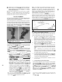
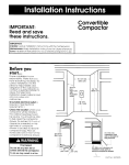
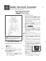
Meade Instruments Corporation
6001 OAK CANYON, IRVINE, CALIFORNIA 92620-4205 n (949) 451-l 450
FAX: (949) 451-1460 n www.meade.com
Operating Instructions
Meade@ ETX Field Tripod
For Use With the ETX Astro Telescope
b.
Attaching the Accessory Tray:
Remove the round accessory tray (6), Fig. 1, from the
shipping box. Remove the black, star-shaped lock knob
from the threaded rod on the bottom of the accessory tray.
Attach the tray to the tripod by inserting the threaded rod
through the central hub of the extension strut (7) Fig. 1.
Rethread the lock knob onto the accessory tray.
Varying the Tripod Height:
Loosen the black, star-shaped height adjustment knob (5)
Fig. 1, at the base of each tripod leg.
Slide the three top tripod leg sections to the desired height.
Tighten the three height adjustment knobs, (5) Fig. 1, to a
“firm feel”. Do not overtighten.
Collapsing the Tripod for Storage:
Remove the accessory tray (6), Fig. 1, from the tripod.
Grasp the top of the tripod wrth one hand, and with the
other hand, pull up on the central hub of the extension
strut (7) Fig. 1, where the accessory tray was attached.
This action will cause the tripod legs to move inward to a
collapsed position.
Important Notes on using ETX Field Tripod:
.
Remove the accessory tray before attempting to collapse
the tripod.
.
If the tripod does not extend or collapse easily, do not
force the tripod legs in or out. By following the above
instructions the tripod will function properly. Forcing the
tripod into an incorrect position may damage the extension
strut system.
.
Do not overtighten the three star-shaped height adjustment
knobs on the tripod legs. “Firm feel” tightening is sufficient.
L
Fig. 1: ETX Field Tripod. (1) Mounting Slots; (2) Mounting Plate; (3)
Latijude Scale; (4) Fine Latitude Adjustment Knob; (5) Height
Adjustment Knob; (6) Accessory Tray; (7) Extension Strut System;
(6) North-Pointing Tripod Leg (marked “N” at position of arrow);
19) Fine Azimuth Adjustment Knobs; (10) Latitude Lock Knob:
(11) Latitude Lock Lever (opposite side).
2. Attaching the ETX Astro Telescope to the Tripod
PARTS LISTING AND ASSEMBLY
a.
Confirm that the latitude lock lever (11) Fig. 1, is in the
locked posltlon by rotating the lever clockwlse untrl trght.
Also confrrm that the N/S swatch on the base of the E T X
Astro Telescope IS set for the correct hemsphere
b.
In the side of the ETX
drive base, locate the
two attachment holes,
Fig. 2. (These holes
are normally used with
the fixed legs of the
table tripod.) Position
the ETX on the Field
Tripod so that the “N”
When opening the packing box for the first time, note carefully
the following parts included with the ETX Field Tripod:
- Tripod
- 2 Attachment Knobs
- Accessory Tray
.
1. Preparing the Tripod For Use
The ETX Field Tripod (Fig. 1) is simple to set up and easy to
use. Users need only attach the accessory tray and adjust the
tripod to the desrred observtng hetght.
a.
Extending the Tripod:
Remove the tripod from the shtpptng box and stand it
upright. Grasp two of the tripod legs, leaving the full
weight of the tripod on the third leg. Gently pull the legs
apart to a full open posltion.
Fig. 2: ETX Drove Base, showmg
attachment holes.
.
C.
Then, align the two holes in the base of the ETX with the
mounting slots (1) Fig. 1, on the mount plate (2) Fig. 1.
d.
Thread the two provided l/4-20 threaded attachment
knobs through the mounting slots into the ETX base.
Tighten to a firm feel only. Do not overtighten or damage
to the threads may occur.
The ETX Astro Telescope can be used for land or celestial
To track celestial objects, polar alignment is
observing.
required, along with the motor drive system of the ETX. (See
the Motor Drive section of the ETX instruction manual.)
POLAR ALIGNMENT
Polar alignment is the process of lining up the telescope’s polar
axis with the North Celestial Pole (or South Celestial Pole if
observing from the southern hemisphere).
Note: By following the procedures listed above, the ETX
telescope is polar aligned for most celestial observing
applications. See Figure 3. Approximate polar alignment is
sufficient in the great majority of these applications. Do not
allow a time-consuming effort at precise polar alignment to
interfere wifh your basic enjoyment of the telescope, as such
precise alignment is, in general, not reqtiired.
Using the North Star, Polaris, to find North aids in the polar
alignment procedure. Polaris can be found in relation to the Big
Dipper by projecting a line from the so-called “pointer stars” of
the Big Dipper. For southern hemisphere alignment, locate
south by using the faint star Sigma Octans (the South Star)
With a polar aligned ETX, tracking celestial objects is possible
simply by turning on the drive motor in the base of the telescope.
The motor counteracts Earth’s rotation, keeping objects in the
field of view. Also, with a polar aligned telescope, the ETX’s Dee
and R.A. setting circles may be used to locate faint objects
directly from their catalogued coordinates.
0
*...__b
*...“’
Cassiopeia
Fig. 4: Locating Polaris.
2.
Using a Polar Aligned Telescope
Once the telescope is polar aligned, the ETX motor drive will
keep a celestial object in the field of view of the telescope.
a.
To center a celestial object within a polar aligned
telescope, unlock the Dee and R.A. lock levers of the
telescope (see the Locating Astronomical Objects section
of the ETX instruction manual). Do not move the tripod or
adjust the latitude angle when centering an object in the
telescope, as this will destroy the polar alignment.
b.
Once a celestial object has been centered in the
telescope, lock the Dee and R.A. lock levers.
C.
Locate the On/Off switch on the bottom of the ETX drive
base and turn on the motor drive. The motor drive will
keep the celestial object within the telescope’s field of
view.
Fig. 3. (left) The ETX Astro Telescope on Field Tripod. ownted for
land wewIng. (right) The polar-allgned ETX, ready for astronomlcal
wewng.
1.
Polar Alignment Procedures
Make sure the ETX is firmly attached to the tripod, as described
above In this tnstruction sheet, with latitude lock knob (10) and
the latitude lock lever (11) Fig 1. firmly locked
Step (a) below IS equrvalent to pointing the telescope’s polar
axls due north (or due south for observers in the southern
hemisphere). Step (b) IS equrvalent to makrng the telescope’s
latitude angle equal to the latitude angle of your obset-vmg
location.
a.
b.
.
On top of one of the tripod legs, locate the letter “N” (8)
Fig. 1. This represents the north leg of the tnpod. Prck up
the entire telescope-and-tripod and onent the tripod u
tf@ lea marked “N” points due north. For observers In the
southern hemisphere (e.g., Australra), the lea marked “N”
should pornt due south.
Determine the latitude of your observing locatron by
checking a road map, atlas, or refer to pages 12-13 of the
ETX manual. To set the latitude of the tripod to your
obseN!ng location, loosen the latitude lock knob (lo),
Fig. 1. Turn the fine latitude adjustment knob (4) Fig. 1,
clockwise or counterclockwise until the latitude pointer
Indicates the correct latitude on the latitude scale (3) Fig. 1.
It may be necessary to loosen the lock nut on the fine
latitude adjustment knob (4) Fig. 1, to allow enough
movement of the mount to achieve the latitude of your
location. Once the desrred latitude has been set, tighten
the lock nut until it is flush agamst the mount. Trghten the
latitude lock knob (lo), Fig. 1, as well.
.
Note: The fine azimuth adjustment knobs (9), Fig. 7, which
move the telescope horizontally without moving the tripod itself,
may be used to aId m the alignment procedure.
Note:
Depending on the accuracy of the alignment
procedure, it may be necessary to use the R.A. and Dee
Slow Motion Controls to make minor adjustments to keep
the celestial object in the field of view.
d.
The motor drive disengages when the R.A. and Dee lock
levers are unlocked and re-engages when the lock levers
are locked, making it possible for the motor drive to remain
on during the entire observing session.
e.
At the end of an observing session, remember to turn off
the motor drive.
3.
Terrestrial Use of the Field Tripod
In land viewing applications, the three legs of the Field Tripod
may be posrtioned In an arbitrary orientation. The telescope
mounting, however, should be placed in a horizontal positron:
(Fig. 3) by turning the fine latitude adjustment knob (4) Frg. 1,
to read 90”, unlocking and re-lockrng the latitude lock knob‘(lO),
Fig. 1, to accomplish this adjustment. The ETX’s motor drive
Use the
should be turned off In terrestnal applications.
telescope’s R.A. and Dee slow-motion controls for fine motion in
horizontal and vertical.
If you have any questions regarding the use of the ETX Field
Tripod,
please call Meade Customer Service at
(949) 451-1450.
*