1
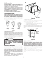
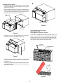
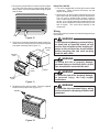
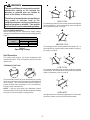
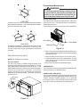
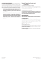
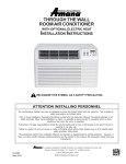
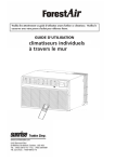
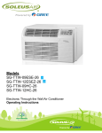
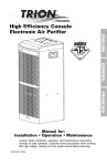
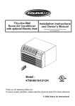
Thru-the-Wall Installation Instructions Room Air Conditioner and Owner’s Manual with optional Electric Heat This manual must be left with the owner of the equipment. Contents IMPORTANT NOTE TO THE OWNER .......................... 2 IMPORTANT NOTE TO THE SERVICER ..................... 2 Unit Features ............................................................... 2 Transportation Damage .............................................. 2 Unpacking The Unit ..................................................... 2 Parts Supplied ............................................................. 2 Unit Accessories .......................................................... 3 Operating Instructions ................................................ 3 Installation Instructions .............................................. 3 Wiring ........................................................................... 5 Unit Operation ............................................................. 6 Preventative Maintenance ........................................... 7 Normal Operating Sounds and Conditions ............... 8 Obtaining Service ........................................................ 8 is a trademark of Maytag Corporation and is used under license to Goodman Company, L.P. All rights reserved. ® ATTENTION INSTALLING PERSONNEL RECOGNIZE THIS SYMBOL AS A SAFETY PRECAUTION. As a professional installer you have an obligation to know the product better than the customer. This includes all safety precautions and related items. Prior to actual installation, thoroughly familiarize yourself with this Instruction Manual. Pay special attention to all safety warnings. Often during installation or repair it is possible to place yourself in a position which is more hazardous than when the unit is in operation. Remember, it is your responsibility to install the product safely and to know it well enough to be able to instruct a customer in its safe use. Safety is a matter of common sense...a matter of thinking before acting. Most dealers have a list of specific good safety practices...follow them. The precautions listed in this Installation Manual are intended as supplemental to existing practices. However, if there is a direct conflict between existing practices and the content of this manual, the precautions listed here take precedence. 2001-2004 Goodman Company, L.P. Effective: August 2004 IMPORTANT NOTE TO THE OWNER Transportation Damage IMPORTANT NOTE TO THE SERVICER In the event of damage: This equipment is to be serviced by professionally trained personnel only. If this equipment is improperly installed, adjusted or altered by an unqualified person, a safety hazard may result. All units are securely packed in shipping containers approved by the National Safe Transit Association. The carton should be checked upon arrival for external damage. If damage is found, immediately make a written request for inspection by the carrier’s agent. Read this manual and familiarize yourself with the specific items which must be adhered to before attempting to service this unit. The precautions listed in this manual should not supersede existing practices but should be considered as supplemental information. 1. Note on the delivery receipt any visible damage to shipment or container. 2. Notify carrier promptly and request an inspection. 3. File the claim with the following supporting documents within the six month statute of limitations. a. Original Bill of Lading, certified copy, or indemnity bond. b. Original paid freight bill or indemnity. c. Original invoice or certified copy, showing trade and other discounts or reductions. d. Copy of the inspection report issued by carrier’s representative at the time damage is reported to the carrier. Unit Features This unit has an exhaust air option which allows you to bring outdoor air into the room. To bring air in from outside, snap in the supplied perforated exhaust air plug (Figure 1) in the location shown in Figure 2. To use only indoor air, snap in the solid exhaust air plug. NOTE: The exhaust air option (perforated plate installed) can be used in any operation mode. The carrier is responsible for making prompt inspection of damage and for a thorough investigation of each claim. The distributor or manufacturer will not accept claims from dealers for transportation damage. Unpacking The Unit 1. Cut the carton banding and open the carton. 2. Remove the literature, hardware pack, upper styrofoam shipping blocks, and styrofoam corner posts. 3. Remove the front assembly. 4. Cut the carton around the perimeter of the box 2” from the bottom and discard the top. 5. Lift the unit from the remaining carton. 6. Dispose of the cardboard and styrofoam at an approved Recycle Center. Check all contents for damaged or missing parts. In case of concealed damage, notify the carrier as soon as possible—preferably within 5 days. Refer to step 3 of the Transportation Damage section if damage or missing parts are noted. Figure 1 Parts Supplied Size 2 1/2” x 1/2” Foam Gasket (54”) 1 Sleeve Clip 2 Blunt Point Sheet Metal Screw 2 Perforated (Fresh Air) Plug 1 Solid (Fresh Air) Plug 1 Plastic Knob 2 Washer Head Sheet Metal Screw 4 #8 x 3/8” #8 x 3/8” 2 Quantity 1/2” x 1” x 14” Foam Gasket EXHAUST AIR PLUG Figure 2 Description Unit Accessories This unit is designed for through-the-wall installation in new or existing buildings. To complete the installation in an existing wall sleeve, a TWKG rear louver panel kit, a TWEAK or TWFAK adapter kit is required. If the sleeve is a GE wall sleeve, use the TWKG rear louver panel kit. If the sleeve is an Emerson wall sleeve, use the TWEAK adapter kit, If the sleeve is a Fedders or Freidrich wall sleeve, use the TWFAK adapter kit. The chassis and wall sleeve are shipped separate. Operating Instructions Check the data specification plate and ensure the proper voltage and current rating for the type of power plug on the unit is available. DO NOT REMOVE THE GROUNDING PRONG FROM THE POWER CORD. See Figure 3 for the types of acceptable plugs. Do not use an extension cord for the installation of this product. Refer to the data specification plate for electrical requirements. Figure 4 SLEEVE INSTALLATION In order for condensate water to drain properly inside the unit, the sleeve must be installed properly: • • 110V 15 amp 230V 15 amp FOAM Level from right to left. A slight downward pitch from the indoor side to the outdoor side as shown in Figure 5. Refer to the Installation Instructions supplied with the wall sleeve for a complete description of the installation procedure. 230V 20 amp Inside Outside Level Figure 3 LCDI or AFCI Power Cords Underwriters Laboratories (UL) and the National Electric Code (NEC) now require power cords that sense current leakage and can open the electrical circuit to the unit. In the event, the unit does not operate, check the reset button located on or near the head of the power cord as part of the normal troubleshooting procedure. Wall Sleeve 1/4 Bubble Tilt To Outside Outside Wall WARNING Figure 5 To prevent property damage, personal injury or death, do not remove grounding prong from plug. Follow all operating instructions. REAR LOUVER PANEL A TWKG rear louver panel kit is required for unit installation into an existing GE 26” wall sleeve. A TWEAK or TWFAK adapter kit is required for unit installation into an existing 27” wall sleeve. The rear louver panel directs air flow for proper unit operation and protects the outdoor coil. The panel must be installed before installing the chassis. These kits are not supplied with the unit. Refer to the Installation Instructions supplied with the rear louver panel kit for a complete description of the installation procedure. Installation Instructions To ensure that the unit operates safely and efficiently, it must be installed, operated, and maintained according to these installation and operating instructions and all local codes and ordinances, or, in their absence, with the latest edition of the National Electrical Code. The proper installation of this unit is described in the following sections. Following the steps in the order presented should ensure proper installation. NOTE: If using a GE wall sleeve, ensure that the rear enclosure panel is removed before installing the TWKG panel. NOTE: Attach the supplied 1/2” x 1” x 14” foam prior to installation of unit. Remove adhesive backing strip and place the foam on unit as shown in Figure 4. 3 CHASSIS INSTALLATION 1. Inspect the ground wire (Figure 6) on the unit and ensure it is attached to the left side panel. If not, attach the wire to the panel. 2. Remove the mounting screw from the left hand side of the existing sleeve (Figure 6). Place the screw through the eyelet on the unattached end of the ground wire of the unit and reinsert into its mounting hole. Ground Wire Clip Screw Figure 8 Mounting Screw FRONT PANEL INSTALLATION Discharge Air Grille Airflow Direction Change - Optional Figure 6 If you wish to change the direction of airflow from up to down, remove the four screws holding the Discharge Air Grille in place (Figure 9). Drop out the grille and rotate 180°. Ensure the notches on the grille face up. Replace the grille and secure in place with the removed screws. 3. Install the 1/2” x 1/2” supplied gasket foam around the top and two sides of the chassis (Figure 7). Foam Screws (4 places typ.) Figure 7 4. Carefully slide the chassis into the sleeve. Ensure that the ground wire is not pinched or in the path of the condenser fan. 5. Fasten the supplied clips to the exposed sides of the unit using the two #8 x 3/8” blunt sheet metal screws provided (Figure 8). Figure 9 4 Discharge Air Grille 1. Remove the grille and filter from the front panel (Figure 10). Doing one side at a time, press the tab on the front panel (Figure 10) with one hand while lifting the grille with the other. IMPORTANT NOTES: 1. The unit is equipped with a rubber-grommet-mounted compressor. These grommets are factory set and require no adjustment. 2. Obstruction to air flow must be checked and removed. Check the indoor and outdoor grilles for obstructions. The unit must be located where curtains, furniture, trees, or other objects do not block air flow to and from the unit. If air is obstructed and/or deflected back into the unit, the air conditioner’s compressor may cycle on and off rapidly. This could cause damage to the compressor. Wiring Before wiring the unit, please review the following warnings and cautions. Figure 10 WARNING To avoid property damage, personal injury or death due to electrical shock, do not service this unit without first shutting off power to the unit from the circuit breaker and/or removing the unit cord set plug from the wall outlet. 2. Using the four washer head sheet metal screws provided, mount the front panel to the chassis through the front panel mounting holes (Figure 11). Mounting Holes Mounting Holes WARNING To avoid the risk of property damage, personal injury or electrical shock, do not use an extension cord with this unit. Front Panel Chassis WARNING To avoid the risk of fire, property damage, or personal injury, use only copper conductors. Mounting Holes Figure 11 WARNING 3. Reattach the filter and front grille. Place the supplied knobs onto the proper stem (Figure 12). To avoid the risk of personal injury, wiring to the unit must be properly polarized and grounded. Knobs Figure 12 5 WARNING This air conditioner is not meant to provide unattended cooling or life support for persons or animals who are unable to react to the failure of this product. OFF OFF HIGH COOL FAN ONLY LOW HEAT FAN ONLY HIGH HEAT The failure of an unattended air conditioner may result in extreme heat in the conditioned space causing overheating or death of persons or animals. Take proper precautions to avoid unattended operation. LOW COOL LOW COOL MED COOL HIGH COOL HIGH COOL This setting provides the most cooling output at the highest efficiency possible. In this mode the fan runs on high and the compressor cycles on and off. VOLTAGE MEASUREMENTS Before connecting the unit, measure the supply voltage. Voltage must fall within the voltage utilization range given in Table 1. OFF HIGH COOL FAN ONLY Operating Voltage Unit Voltage Rating 230/208 115 Voltage Utilization Range Minimum Maximum 197 253 103 126 LOW COOL MED COOL MEDIUM COOL This setting provides quieter operation than High Cool. In this mode the fan runs at medium speed and the compressor cycles on and off. Table 1 Operating Voltage OFF Unit Operation Two rotary knobs (Figure 10) control temperature and operational modes. They are located to the top left of the cabinet front. OFF HIGH COOL THERMOSTAT SETTING LOW COOL LOW COOL HIGH COOL LOW COOL CO O This setting dehumidifies the air and provides the quietest fan operation. In this mode the fan runs at the lowest speed and the compressor cycles on and off. R LE WA R R ME FAN ONLY HIGH HEAT MED COOL COOLER LOW HEAT FAN ONLY OFF The thermostat controls the room temperature by turning either the compressor or electric heater on and off while the fan is running. Turn the thermostat control clockwise to provide a cooler room temperature; turn it counterclockwise to provide a warmer one. LOW HEAT FAN ONLY HIGH HEAT NOTE: If the fan cycle switch (see Additional Control Inputs) is in the CYCLE mode, both the compressor and fan will cycle on and off during the cooling modes. LOW COOL HIGH COOL HIGH HEAT On high heat, the fan runs at its highest speed. In this mode the electric heater cycles on and off by thermostat. 6 Preventative Maintenance OFF WARNING LOW HEAT FAN ONLY HIGH HEAT To prevent personal injury or death due to electrical shock, unplug the unit at the wall outlet or turn off power at the fuse box or circuit breaker before servicing the unit. LOW COOL HIGH COOL INTAKE AIR FILTER The intake air filter should be cleaned when it is dirty or at least once a month. The intake air filter is constructed of durable polypropylene. LOW HEAT On low heat, the fan runs at its lowest speed and provides the quietest fan operation. In this mode the electric heater cycles on and off by thermostat. OFF OFF HIGH COOL FAN ONLY LOW HEAT FAN ONLY HIGH HEAT MED COOL The following procedure is used to remove the intake filter: LOW COOL LOW COOL Front Grille HIGH COOL Front Panel FAN ONLY Intake Air Filter This setting circulates air. If the exhaust air option is used, this setting will exhaust stale indoor air. In this mode, the fan runs continuously at high speed without compressor operation. Figure 14 1. Remove the grille by pressing the tabs one at a time on the front panel (Figure10) with one hand while lifting the grille with the other. 2. Remove intake air filter (Figure 14) from front panel. 3. Clean filter with a vacuum or running water. If using water, please be sure that the filter is not excessively wet when replaced. 4. Reverse this procedure to reinstall the filter. ADDITIONAL CONTROL INPUTS NOTE: Not available on all models. Fan Cycle Switch The fan cycle switch is located behind the plastic front assembly underneath the control knob (Figure 13). The fan cycle switch sets the operational mode of the fan. In the CONTINUOUS position, the fan will run continuously whenever the unit is in the heat or cool mode. In the CYCLE position, the fan will cycle on and off with the compressor when the unit is in the cool mode. This switch can only be set by a servicer. COMPRESSOR The compressor is hermetically sealed, permanently lubricated and requires no additional oiling. FRONT PANEL AND GRILLE The front panel and grille can be cleaned with a mild soap or detergent. Do not use hydrocarbon-based cleaners (e.g. acetone, benzene, naphtha, gasoline, etc.) to clean the front panel or grille. Use care when cleaning the control area. Do not use an excessively wet cleaning cloth. Fan Cycle Switch C ONT Tabs INU OUS CY CLE Figure 13 7 SCHEDULED MAINTENANCE To achieve continuing top performance and high efficiency, a regular cleaning/inspection schedule must be established. Maintaining this schedule can be accomplished by either a local maintenance staff or an authorized servicer and must follow the instructions described in this manual. • If the unit is operated in a dusty climate, dust may collect in the basepan and clog the condenser coil. It is advisable to remove the unit from the sleeve and thoroughly clean the basepan and condenser coil on a periodic basis. • If the unit is installed ocean side or in a corrosive atmosphere, its life may be greatly reduced by the corrosive environment. Under these conditions, the unit should be removed from the sleeve and completely cleaned once a year. At that time any scratches or blisters on the painted surfaces should be sanded and repainted. Normal Operating Sounds and Conditions POPPING OR GURGLING SOUNDS This sound is the refrigerant traveling through the lines. This is a normal sound which may be heard for a few seconds after the unit shuts off. WATER TRICKLING SOUNDS This sound is produced by the water as it is picked up and run over the coils. This procedure improves the efficiency of the unit and helps with water removal. WATER DRIPPING Water will collect in the basepan during high humidity days. STARTING DELAY You may notice a short delay in the startup if you try to restart the unit too soon after turning it off or if you adjust the thermostat right after the compressor has shut off. This delay protects the compressor. Obtaining Service In the unlikely event this unit requires repair or servicing beyond what is covered in this manual, contact an authorized service organization. To obtain an authorized servicer, contact your sales representative or agency. Part No. 20350002 Printed in USA 2001-2004 Goodman Company, L.P. Effective: August 2004