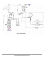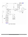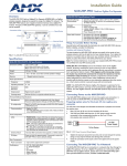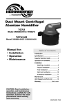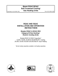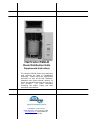
1
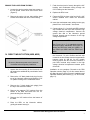
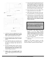
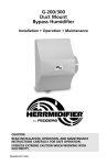
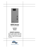
Herrtronic RDU-D
Room Distribution Units
Supplemental Instructions
The Herrtronic RDU-D Series room distribution
units represent the latest in humidification
technology. Please read these supplemental
instructions as well as the MD Installation,
Operations and Service Manual carefully for
trouble free operation and to get the most out of
your purchase.
For further information
concerning this project, contact your local
Herrmidifier representative.
101 McNeill Road • Sanford, NC 27330
Phone: 800-884-0002 • Fax: 800-458-2379 • Email:
[email protected] www.herrmidifier.com
OM-102• June 2005
TABLE OF CONTENTS
I.
Page
Limited Warranty .............................................................................................................................. 3
II. General Description.......................................................................................................................... 3
Mounting Option .......................................................................................................................... 3
Accessory Envelope Contents ................................................................................................... 4
RDU-D Dimensions ....................................................................................................................... 4
III. Installation Preparation .................................................................................................................... 4
IV. Direct Mount Option ......................................................................................................................... 5
MDS with Direct Mount RDU ....................................................................................................... 6
MDD (2) with Direct Mount RDU ................................................................................................. 6
V. Remote Mount Option ...................................................................................................................... 6
MDS, ADS with Remote RDU ....................................................................................................... 8
MDD with Remote RDU................................................................................................................. 8
VI. RDU Operation .................................................................................................................................. 8
Steam Plume Chart ....................................................................................................................... 8
VII. Troubleshooting Guide.................................................................................................................... 9
VIII. Parts List ........................................................................................................................................ 10
Exploded View .......................................................................................................................... 10
IX. Wiring Diagrams .................................................................................................................................
RDU-D with Transformer .......................................................................................................... 11
RDU-D with out Transformer ................................................................................................... 12
MDS/MDM Control to (2) RDU-D Units .................................................................................... 13
2
Herrtronic RDU-D Supplemental Instructions
II. GENERAL DESCRIPTION
I. LIMITED WARRANTY
Seller warrants the equipment of its manufacturing to be
free from defects in workmanship and material for a
period of 24 months after shipment. This warranty is
limited, however, to the repair or replacement of
defective equipment, which is returned, freight prepaid,
to Seller's factory.
The RDU-D Series Room Distribution Units are designed
as a companion module for all AD and MD Series
Herrtronic humidifiers. The RDU may be directly
mounted on top of the Herrtronic cabinet or mounted
remotely. The RDU consists of a fan, controls, & steam
hose to distribute the steam directly into the space.
RDU-D must he remotely mounted when used with
MDM or ADM series humidifiers.
This limited warranty does not apply to any part or
component that is damaged in transit or when handling,
has been subject to misuse, negligence or accident, has
not been installed, operated or serviced according to
Seller's instructions, or has been operated beyond the
factory-rated capacity or has been altered in any way.
Seller's liability is limited to replacement of defective
parts or components and does not include any cost of
labor (including, but not limited to, labor required to
remove and/or reinstall any defective part) other than
Trion/Herrmidifier factory labor.
Each of the Herrtronic series of steam generating
humidifiers contains a plastic steam generating cylinder
that is to be considered a routinely disposable part to be
changed at regular maintenance intervals at the user's
expense. This steam generating cylinder is not covered
by this Warranty. If, after the first installation of your
Herrtronic humidifier, you feel the steam generating
cylinder is not operating normally, you should contact
your Herrmidifier Representative with an explanation of
the problem. However, in the continuing operation of this
humidifier, replacements of this part are your
responsibility as part of routine maintenance.
Trion/Herrmidifier shall not be responsible for loss of use
of any product, loss of time, inconvenience, or damage
to other equipment, or any other indirect or
consequential damage with respect to property whether
as a result of breach of warranty, neglect, or otherwise.
THE WARRANTIES AND LIABILITIES SET FORTH
ARE IN LIEU OF ALL OTHER WARRANTIES AND
LIABILITIES, EXPRESSED OR IMPLIED, IN LAW OR
IN FACT, INCLUDING IMPLIED WARRANTIES OF
MERCHANTABILITY
AND
FITNESS
FOR
PARTICULAR PURPOSE.
Electrical
Capacity
Characteristics
RDUD-D-1
208-240-1-50/60
5-50 lbs/hr.
RDU-D-1T
380-600-1-50/60
RDU-D-2
208-240-1-50/60
51-125 lbs/hr.
RDU-D-2T
380-600-1-50/60
RDU-D-2R
208-240-1-50/60
RDU-D-2L
208-240-1-50/60
126-250 lbs/hr.
RDU-D-2TR
440-600-1-50/60
RDU-D-2TL
440-600-1-50/60
Note: 1T & 2T models include a transformer to provide
208/230 single phase power to the RDU.
Note: MDD Units require two RDU units. For Direct
Mount you must use a specific right and left mount unit
as described below. For remote mount, you will need
two Identical units.
Model No.
For remote mounting applications, the plumbing and
electrical connections may be routed through the bottom
or back of the RDU. There are two electrical knockouts,
two steam supply knockouts and one condensate return
knockout on both the bottom and back to facilitate
installation.
The foregoing shall constitute the total liability of seller in
the case of defective performance of all or any of the
equipment or services provided to Buyer. Buyer agrees
to accept and hereby accepts the foregoing as the sole
and exclusive remedy for any breach or alleged breach
of warranty by Seller.
Herrtronic RDU-D Supplemental Instructions
3
As shipped, the RDU is set up for direct unit mounting.
New wiring and condensate return tubing (supplied) will
be required for remote mounting. Be sure to use 18
gauge (minimum) copper conductor wire with insulation
rated for 600 VAC. Supply power may originate from the
Herrtronic humidifier or a separate supply. If a separate
source is used, be sure to install a dedicated power
disconnect. All hardware and accessory components
required for installation are included as listed below:
ACCESSORY CONTENTS
Item
Quantity
Compression Sleeve
1
Compression Nut
1
#8 x ½” Stainless steel sheet metal screw
4*
¾” I.D. Plastic bushing
2
3” Diameter plastic hole plug
2
5/16” I.D. Plastic bushing
1
Steam inlet union
1*
2 ½” Stainless steel hose clamp
3*
¼” x 2” Lag screw
2
#8 –32 x 3/8” Stainless steel machine screw
4
Brass insert
1
¼” O.D. Condensate return tubing
20’
*-Double quantity for RDU-D-2 series units
* Not in accessory envelope
The RDU unit must either be placed higher than the
Herrtronic unit or provisions for handling the condensate
via an external drain must be made. The following chart
details the physical clearances around the cabinet for
servicing the unit. Figure 13 details the clearances
required due to the steam plume. (Page 8)
MINIMUM CLEARANCES AROUND CABINET
LEFT
15”
RIGHT
15”
TOP*
2”
BOTTOM
0”
* Subject to output, fan speed and room conditions
NOTE:
The steam plume should not impinge on walls,
ceilings or other objects. Supply air registers, if
present, must be directed away from RDU.
III. Installation Preparation
WARNING !
Disconnect power to the humidifier while installing
RDU.
Herrtronic RDU-D Supplemental Instructions
4
REMOVE THE COVER FROM THE RDU
1. Loosen the two hex socket head set screws on
the fan speed control knob and remove knob
(Figure 6).
2. Remove the twelve (six per side) phillips head
screws which fasten the cover to the housing.
7. Feed the wires (total of seven) through the 3/4"
bushing and condensate tubing through the
5/16" bushing into the Herrtronic.
8. Replace the RDU cover.
9. Fasten the RDU in place using four #8-32 x 3/8"
screws installed from inside the Herrtronic
cabinet.
10. Insert the condensate return tubing into the grey
plastic fill tee. It will extend I" into the tee.
11. Connect wires # 1 -6 to the 6 pole RDU terminal
strip located near the top of the Herrtronic high
voltage electrical compartment. Connect the
ground wire #24 to the Herrtronic ground
terminal located near the bottom of the high
voltage compartment.
NOTE
See Figure 16 or 17 for standard electrical
hookup for MDS, and MDD'S. See Figure 18
where two RDU's are used per cylinder; i.e.
two RDU's per MDS and four RDU's per
MDD.
IV. DIRECT MOUNT OPTION (MDS, MDD)
WARNING!
Be sure to disconnect power to the Herrtronic
Humidifier before beginning installation.
1. Assure that the mounting for the Herrtronic unit
will support the additional 40 pound load of each
RDU unit.
2. Remove the 1/2" black plastic hole plug from the
top of the Herrtronic cabinet and install the 5/16"
I.D. plastic bushing for the condensate return.
12. On MD models, remove jumper wire #39 from
the Herrtronic 12 pole controls terminal strip
located in the low voltage electrical compartment
between poles #1 and #2. On AD models,
remove jumper wire #37 from the Herrtronic 6
pole RDU terminal strip located in the high
voltage electrical compartment between poles
#2 and #5.
Installation is now complete. Proceed to the RDU
Operation section (Page 10) of this manual then to
the Start-Up section of the Herrtronic Installation and
Operation Manual (MD manual, pg. 14; AD manual,
page 11).
3. Remove the 1" black plastic hole plug(s) from
the top of the Herrtronic cabinet.
4. Remove the rearmost 7/8" knockout from the
bottom of the RDU and install one 3/4" I.D.
plastic bushing from the inside.
5. Remove the 3/4" knockout from the bottom of
the RDU.
6. Place the RDU on the Herrtronic cabinet,
guiding the steam hose(s) in.
Herrtronic RDU-D Supplemental Instructions
5
V.
REMOTE MOUNT OPTION
(MDM, MDS, MDD)
1. The RDU may hang directly on a wall using the
two 1/4" x 2" lag screws included. There are two
key-hole slots on the back of the cabinet which
engage these screws. Be certain that: 1) the
screws are fastened securely enough to the wall
to support the 40 lbs. weight of each RDU unit,
and 2) the screws are level. Turn the screws in
until the heads are 1/8" away from the mounting
surface.
2. Hang the unit on the wall and tighten the two lag
screws.
3. The steam hose(s) is to be connected using the
steam inlet union(s) (Figure 9).
4. Trim the orange steam hose(s) which is
connected to the manifold so that it fits properly
onto the union(s) and secure connections with a
hose clamp(s).
5. Fasten steam inlet union(s) to bottom of RDU
cabinet with screws provided.
6. Remove the 1/2" black plastic hole plug from the
top of the Herrtronic cabinet and install the 5/16"
I.D. plastic bushing (included).
7. Remove the 18" piece of condensate return
tubing from the manifold elbow.
Herrtronic RDU-D Supplemental Instructions
6
13. There are a total of seven wires which are to be
connected between the RDU and the Herrtronic
unit. The RDU receives all of its power and
control from the Herrtronic unit. Use the two
7/8" knockouts on the bottom or back of the
RDU cabinet and the two 7/8" knockouts on the
top of the Herrtronic cabinet for wiring conduit.
14. Wires #3 and #4 are the high voltage power
supply and should be run in one conduit.
15. Along with the ground wire #24, wires #1, #2,
#5, and #6 should be run in the second conduit.
16. Connect wires # 1-6 to the 6 pole RDU terminal
strip located near the top of the Herrtronic high
voltage electrical compartment. Connect the
ground wire #24 to the Herrtronic ground
terminal located near the bottom of the high
voltage compartment.
NOTE
See Figure 16 or 17 for standard electrical
hookup for MDS, and MDDS. See Figure 18
where two RDUs are used per cylinder; i.e. two
RDUs per MDS and four RDUs per MDD.
8.
Uncoil the 10' piece of condensate return tubing
(drain line), feed into the RDU cabinet, from the
bottom or back, and connect to the manifold
elbow using the compression sleeve and nut.
9.
Run the condensate return tubing down into the
Herrtronic cabinet through the 5/16” I.D. plastic
bushing.
10.
The condensate tubing can be attached to the
steam hose or electrical conduit interconnecting
the RDU and Herrtronic with cable ties or
equivalent.
11.
After the condensate tubing is secured, insuring
that there are no kinks or low spots, the length
should be trimmed so that it can extend 1" into
the grey plastic fill tee in the Herrtronic unit. Now
insert the tubing into the fill tee.
12.
National, state or local electrical codes may
require the use of two separate conduits - one
for high voltage supply power and one for control
wiring.
17. On MD models, remove jumper wire #39 from
the Herrtronic 12 pole controls terminal strip
located in the low voltage electrical
compartment between poles #1 and #2. On AD
models, remove jumper wire #37 from the
Herrtronic 6 pole RDU terminal strip located in
the high voltage electrical compartment
between poles #2 and #5.
18. Replace the RDU cover and the fan speed
control knob.
Installation is now complete. Proceed to the RDU
operation section then to the start-up section of the
Herrtronic Installation, Operations and Service Manual.
Herrtronic RDU-D Supplemental Instructions
7
VI. RDU OPERATION
Upon starting the Herrtronic unit, the RDU fan will be
energized. If airflow is not sensed within ten seconds,
the Herrtronic unit will shutdown and a fault will be
registered. Depress '”Fault" button to confirm fault
condition and clear fault by pressing "Enter” and then
"Back” button to return to Menu 1. Herrtronic AD Series
will not run while the air proving switch does not indicate
proper airflow to the unit.
Once operating, the fan speed can be adjusted
continuously from 1—5 (slow—fast) by turning the fan
speed control knob. Refer to the chart below for the
optimum fan speed setting for your application.
Figure 13
STEAM PLUME (@ 75° F, 55% R.H.)
Throw (in.)
Blower Speed (CFM)
Output
lbs. Per hr
Breadth (in.)
Blower Speed (CFM)
Rise (in.)
Blower Speed (CFM)
1
(210)
2
(240)
3
(280)
4
(320)
5
(365)
1
(210)
2
(240)
3
(280)
4
(320)
5
(365)
1
(210)
2
(240)
3
(280)
4
(320)
5
(365)
100
90
80
70
60
50
40
30
20
112
98
90
50
120
112
92
80
35
126
136
130
126
126
116
90
75
30
138
144
138
132
130
120
94
70
35
156
156
156
138
134
120
100
60
35
40
36
28
20
36
36
36
26
20
60
58
48
42
34
36
36
24
18
60
52
42
40
28
36
32
24
18
48
46
40
36
28
30
26
24
18
36
18
10
-
58
22
12
-
120
72
52
36
30
12
6
-
50
36
24
20
14
6
-
25
20
16
12
6
-
10
20
15
-
-
-
15
15
-
-
-
-
-
-
-
WARNING!
To avoid potential contact with steam, be certain to shut off the Herrtronic unit BEFORE adjusting the louvers.
Herrtronic RDU-D Supplemental Instructions
8
When the Herrtronic unit is turned "off”, either by switch
or controller, the RDU fan will continue to operate for 15
minutes to prevent the formation of condensate inside
the cabinet. The steam plume direction can be controlled
both horizontally and vertically by adjusting the louvers
on the air discharge grille. Louvers adjusted as shown in
Figure 14 produce the most consistent and shortest
evaporation distance.
Problem / Symptom
Steam Condensing on RDU
sheetmetal or other objects.
Fan not energizing
Fan speed adjustment not working.
Reason - Correction
TROUBLESHOOTING GUIDE
Adjust louvers per figure 14
1. Check that the fan rotates freely.
2. Check fuses in RDU.
3. Check wiring to fan.
4. Check voltage to fan - should be 220 VAC +/- 10%.
5. Replace fan and capacitor. (EST – 1402, EST-1408)
1. Replace rheostat.
Water spitting out of manifold
1. Check condensate drain hose. If it is clogged, clean.
2. Make sure condensate drain hose is sloped properly and there are no
low spots or kinks.
Fan does not continue to operate
for 15 minutes after Herrtronic
shuts down.
1. Check wiring to relay/timer.
2. Check that the 24 VAC is present between terminal #2 and #3 on relay
timer. If so, replace timer.
Air pressure switch not closing.
1. Fan speed setting too low. Increase fan speed.
2. Check tubing on switch for clogging or out of position.
3. Faulty air pressure switch. Replace.
Blown fuses in RDU
1. Check fan for short circuit.
2. Check RDU wiring for short.
Herrtronic RDU-D Supplemental Instructions
9
VIII. PARTS
LIST
VIII
Troubleshooting Guide
1847C
Quick Connects
EST-1406
2413A
EST-165
EST-230
EST-263
EST-531
EST-1140
EST-1401
¼ “ Tubing
SS Hose Clamp
Steam Hose
Differential Pressure Switch
5 – Pole Terminal Rail
Hole Plug
Distribution Grille
EST-1407
EST-1409
EST-1410
EST-1416
EST-1425
EST-1430
EST-1447
EST-1402 Blower
EST-1403 Inlet Blower Ring
EST-1458
Transformer (RDU-D-IT and 2T
Only)
Fan Speed Control Knob
Bushing
Bushing
Fuseholder
Fuse, 1/2A
Gasket
Manifold Assembly (Specify
Model number )
Steam Inlet Union
EST-1405 Relay Timer
10
Herrtronic RDU-D Supplemental Instructions
Herrtronic RDU-D Supplemental Instructions
11
Herrtronic RDU-D Supplemental Instructions
12
Herrmidifier
101 McNeill Road
Sanford, NC 27330, USA
Phone: 800-884-0002
Fax: 800-458-2379
[email protected]
A FEDDERS ENGINEERED PRODUCTS COMPANY
www.herrmidifier.com
Herrtronic RDU-D Supplemental Instructions
Trion, Ltd.
The Cavendish Centre
Winnall Close
Winchester, Hampshire,
SO23 OLB, UK
Phone: +44 (0) 1962 840465
FAX:
+44 (0) 1962 828619
E-mail: [email protected]
13