1
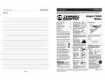
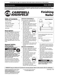
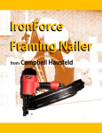
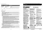
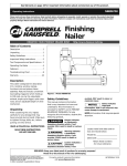
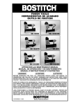
See Warranty on page 8 for important information about commercial use of this product.
Operating Instructions
MXN064
Limited Warranty
1.
DURATION: From the date of purchase by the original purchaser as follows: Campbell Hausfeld (Standard Duty and
Unannounced) – One (1) Year, (Serious Duty) – Two (2) Years, (Extreme Duty) – Three (3) Years; IronForce by Campbell
Hausfeld – One (1) Year; Farmhand – Three (3) Years; Maxus – Five (5) Years.
2. WHO GIVES THIS WARRANTY (WARRANTOR): Campbell Hausfeld / Scott Fetzer Company, 100 Production Drive,
Harrison, Ohio, 45030, Telephone: (800) 543-6400
3. WHO RECEIVES THIS WARRANTY (PURCHASER): The original purchaser (other than for purposes of resale) of the
Campbell Hausfeld product.
4. WHAT PRODUCTS ARE COVERED BY THIS WARRANTY: Any Campbell Hausfeld nailer, stapler, air tool, spray gun, inflator or air accessory supplied or manufactured by Warrantor.
5. WHAT IS COVERED UNDER THIS WARRANTY: Substantial defects in material and workmanship which occur within the
duration of the warranty period.
6. WHAT IS NOT COVERED UNDER THIS WARRANTY:
A. Implied warranties, including those of merchantability and FITNESS FOR A PARTICULAR PURPOSE ARE LIMITED
FROM THE DATE OF ORIGINAL PURCHASE AS STATED IN THE DURATION. If this product is used for commercial,
industrial or rental purposes, the warranty will apply for ninety (90) days from the date of purchase. Some States
do not allow limitation on how long an implied warranty lasts, so the above limitations may not apply to you.
B. ANY INCIDENTAL, INDIRECT, OR CONSEQUENTIAL LOSS, DAMAGE, OR EXPENSE THAT MAY RESULT FROM ANY
DEFECT, FAILURE, OR MALFUNCTION OF THE CAMPBELL HAUSFELD PRODUCT. Some States do not allow the exclusion or limitation of incidental or consequential damages, so the above limitation or exclusion may not apply to
you.
C. Any failure that results from an accident, purchaser’s abuse, neglect or failure to operate products in accordance
with instructions provided in the owner’s manual(s) supplied with product. Accident, purchaser's abuse, neglect or
failure to operate products in accordance with instructions shall also include the removal or alteration of any safety
devices. If such safety devices are removed or altered, this warranty is void.
D. Normal adjustments which are explained in the owner’s manual(s) provided with the product.
E. Items or service that are normally required to maintain the product, i.e. o-rings, springs, bumpers, debris shields,
driver blades, fuses, batteries, gaskets, packings or seals, fluid nozzles, needles, sandblast nozzles, lubricants, material hoses, filter elements, motor vanes, abrasives, blades, cut-off wheels, chisels, chisel retainers, cutters, collets,
chucks, rivet jaws, screw driver bits, sanding pads, back-up pads, impact mechanism, or any other expendable part
not specifically listed. These items will only be covered for ninety (90) days from date of original purchase.
Underlined items are warranted for defects in material and workmanship only.
F. Cosmetic defects that do not interfere with the product’s function.
7. RESPONSIBILITIES OF WARRANTOR UNDER THIS WARRANTY: Repair or replace, at Warrantor’s option, products or components which are defective, have malfunctioned and/or failed to conform within duration of the warranty period.
8. RESPONSIBILITIES OF PURCHASER UNDER THIS WARRANTY:
A. Provide dated proof of purchase and maintenance records.
B. Deliver or ship the Campbell Hausfeld product or component to the nearest Campbell Hausfeld Authorized Service
Center. Freight costs, if any, must be borne by the purchaser.
C. Use reasonable care in the operation and maintenance of the products as described in the owner’s manual(s).
9. WHEN WARRANTOR WILL PERFORM REPAIR OR REPLACEMENT UNDER THIS WARRANTY: Repair or replacement will be
scheduled and serviced according to the normal work flow at the servicing location, and depending on the availability
of replacement parts.
This Limited Warranty applies in the United States, Canada and Mexico only and gives you specific legal rights. You may
also have other rights which vary from state to state or country to country.
Model MXN064
Operating Instructions
Please read and save these instructions. Read carefully before attempting to assemble, install, operate or maintain the product described.
Protect yourself and others by observing all safety information. Failure to comply with instructions could result in personal injury, death and/or
property damage! Retain instructions for future reference.
Finishing
Nailer
Table of Contents
General Safety . . . . . . . . . . . . .1-3
Specifications . . . . . . . . . . . . . . .2
Operating The Nailer . . . . . . .3-5
Operational Mode . . . . . . . . . . .4
Troubleshooting . . . . . . . . . . . . .7
Warranty . . . . . . . . . . . . . . . . . . .8
Description
This nailer is designed for decorative
trim, molding, window casings, furniture trim and picture frame assembly.
Features include: convenient rear loading magazine which holds up to 100
nails, no-mar tip, adjustable exhaust,
single cycle trigger, quick clear nose,
and an adjustable depth of drive mechanism.
General Safety
Information
CALIFORNIA PROPOSITION 65
You
!
can create dust when you cut,
;;;;;;
;;;;;;
;;;;;;
sand, drill or grind materi;;;;;;
;;;;;;
als such as wood, paint,
metal, concrete, cement, or other
masonry. This dust often contains
chemicals known to cause cancer, birth
defects, or other reproductive harm.
Wear protective gear.
OPERATOR’S RESPONSIBILITY:
The tool operator is responsible for:
• Reading and understanding tool
labels and manual.
• Selecting an appropriate tool actuation system, taking into consideration the work application for which
the tool is used.
• The safe use of the tool.
• Ensuring that the
tool is used only
when the operator
and all other personnel in the work area
are wearing ANSI Z87 eye protection equipment, and when
required, other appropriate protection equipment such as head, hearing and foot protection equipment.
Serious eye or permanent hearing
loss could result.
• Assuring that the tool is kept in safe
working order as described in this
manual.
Locate model number on decal, date
code on body and record below:
Model No. ________________________
Date Code ________________
Retain these numbers for
future reference.
tion equipment such as head, hearing and foot protection equipment.
Serious eye or permanent hearing
loss could result.
Assuring that the tool is kept in
safe working order as described in
this manual.
Assuring the proper maintenance
of all tools in employer’s possession.
Ensuring that tools which require
repair are not further used before
repair. Tags and physical segregation are recommended means of
control.
EMPLOYER’S RESPONSIBILITY:
•
DANGER
This manual contains safety, operational and maintenance information.
Contact your Maxus representative if
you have any questions.
Model MXN064
•
•
•
Selecting an appropriate tool actuation system, taking into consideration the work application for which
the tool is used.
Ensuring that this manual is available to operators and personnel
performing maintenance.
The safe use of the tool.
Enforcing that the
tool is used only
when the operator
and all other personnel in the work area
are wearing ANSI Z87 eye protection equipment, and when
required, other appropriate protec-
•
•
•
Danger indicates
an imminently hazardous situation which, if not avoided,
WILL result in death or serious injury.
!
DANGER
REMINDER: Keep your dated proof of purchase for warranty purposes! Attach it to this manual or file it for safekeeping.
8
Maxus Nailers meet or exceed Industries’
Standards as set forth by the American
National Standard Institute/International
Staple, Nail and Tool Association in ANSI/ISANTA SNT-101-2002.
© 2004
IN277100AV 4/04
Model MXN064
Operating Instructions
General Safety
Information (Continued)
Read and understand
tool labels and manual.
Failure to follow warnings, dangers, and cautions could result in
DEATH or SERIOUS INJURY.
Do not use any type
of reactive gases,
including, but not limO
ited to, oxygen and
CO2
combustible gases, as
a power source. Use
filtered, lubricated, regulated compressed air only. Use of a reactive
gas instead of compressed air may
cause the nailer to explode which
will cause death or serious personal
injury.
Use only a pressureregulated compressed
air source to limit the
air pressure supplied
to the tool. The regulated pressure must
not exceed 110 psi. If the regulator
fails, the pressure delivered to the
tool must not exceed 200 psi. The
nailer could explode which will
cause death or serious personal
injury.
Never use gasoline
or other flammable
liquids to clean the
nailer. Never use the
nailer in the presence
of flammable liquids or gases.
Vapors could ignite by a spark and
cause an explosion which will result
in death or serious personal injury.
location. Always reconnect the air
line BEFORE loading any fasteners.
Do not load the tool with fasteners
when either the trigger is depressed
or the Work Contact Element (WCE)
is engaged. The nailer could eject a
fastener causing death or serious
personal injury.
Always remain in
a firmly balanced
position when
using or handling
the nailer.
Do not remove,
tamper with, or
otherwise cause
the Work Contact
Element (WCE) or
trigger to become
inoperable. Do not operate any tool
which has been modified in a like
fashion. Death or serious personal
injury could result.
Always fit tool
with a fitting
or hose coupling on or
near the tool in
such a manner
that all compressed air in the tool is
discharged at the time the fitting or
hose coupling is disconnected. Do
not use a check valve or any other fitting which allows air to remain in the
nailer. Death or serious personal
injury could occur.
Do not touch the
trigger unless driving nails. Never
attach air line to
nailer or carry
nailer while
touching the trigger. The tool could
eject a fastener which will result in
death or serious personal injury.
CAMPBELL
HAUSFELD
PROFESSIONAL
Warning indicates
a potentially
hazardous situation which, if not avoided, COULD result in death or
serious injury.
! WARNING
Always disconnect the tool
from the power
source when
unattended,
performing any
maintenance or repair, clearing a
jam, or moving the tool to a new
Never place hands or
any other body parts in
the nail discharge area
of the nailer. The nailer
might eject a fastener
and could result in
death or serious personal injury.
Never carry the
nailer by the air
hose or pull the
hose to move the
nailer or a compressor. Keep
hoses away from
heat, oil and sharp edges. Replace
any hose that is damaged, weak or
worn. Personal injury or tool damage could occur.
Nailer Components And Specifications
Troubleshooting Guide
Stop using nailer immediately if any of the following problems occur. Serious
personal injury could result. Any repairs or replacements must be done by a Qualified Service Person or
Authorized Service Center.
! WARNING
Problem
Air leaking at trigger valve
• LENGTH: 12-1/2”
Element (WCE)
Tighten screws
Damaged O-Rings
Replace O-Rings
Damage to bumper
Replace bumper
Air leaking between hous-
Loose screws
Tighten screws
ing and cap
Damaged gasket
Replace gasket
Nailer skips driving nail
Worn bumper
Replace bumper
Dirt in nose piece
Clean drive channel
Dirt or damage prevent nails or pusher
Clean magazine
from moving freely in magazine
Damaged pusher spring
Replace spring
Inadequate air flow to nailer
Check fitting, hose or compressor
Worn O-Ring on piston or lack of lubri-
Replace and lubricate O-Rings
cation
Damaged O-Ring on trigger valve
Replace O-Rings
Air leaks
Tighten screws and fittings
Cap gasket leaking
Replace gasket
Nailer runs slow or has loss
Nailer not lubricated sufficiently
Lubricate nailer
of power
Broken spring in cylinder cap
Replace spring
Exhaust port in cap is blocked
Replace damaged internal parts
Guide on driver is worn
Replace guide
Nails are not correct size
Use only recommended nails
Nails are bent
Replace with undamaged nails
Magazine or nose screws are loose
Tighten screws
Driver is damaged
Replace driver
O-Rings or seals are damaged
Replace O-Rings or seals
Air leaking at trigger valve
stem
Pusher
• WEIGHT: 3 lbs., 14 oz.
Nail Loading
Slot
Quick Clear Catch
• HEIGHT: 11”
• MAXIMUM PRESSURE: 110 psi
• PRESSURE RANGE: 70 - 110 psi
Trigger
No-Mar Tip
2
Work
Contact
Element (WCE)
Magazine
Replace O-Rings. Check operation of Work Contact
ing and nose
Warning Labels (top and back side)
Depth Adjustment
Wheel
O-Rings in trigger valve housing are
Loose screws in housing
• AIR INLET: 1/4” NPT
• NAIL SIZE RANGE: 1” to 2-1/2”
Solution
Air leaking between hous-
Adjustable Exhaust
• MAGAZINE CAPACITY:
100 Nails per load, 16 gauge
Cause
damaged
Nails are jammed in nailer
• REQUIRES: 1.7 SCFM with 10 nails
per minute @ 90 psi
Model MXN064
Operating Instructions
No-Mar tip
Storage
(back side)
7
Interchange Information
Can use 1” to 2-1/2” 16 gauge finish nails designed for the following tools:
• Bostitch® SB-1664FN
• Campbell Hausfeld NB0064
• Dewalt® D51256K
• Hitachi® NT65A2
• Paslode® 3250-F16
• Porter Cable® FN250
• Senco® Finish Pro® 32
General Safety
Information (Continued)
Always assume the nailer contains
nails. Respect the tool as a working
implement; no horseplay. Always
keep others at a safe distance from
the work area in case of accidental
discharge of nails. Do not point the
tool toward yourself or anyone
whether it contains fasteners or not.
Accidental triggering of the nailer
could result in death or serious personal injury.
Do not drive a
nail on top of
other nails. The
nail could glance
and cause death
or a serious puncture wound.
Notes
Model MXN064
Operating Instructions
O I L
Model MXN064
Operating Instructions
Do not operate
or allow anyone ! WARNING
else to operate
the nailer if any
warnings or
warning labels
are not legible. Warnings or warning
labels are located on the nailer magazine and body.
Do not drop or throw the tool.
Dropping or throwing the tool can
result in damage that will make the
tool unusable or unsafe. If the tool
has been dropped or thrown, examine the tool closely for bent, cracked
or broken parts and air leaks. STOP
and repair before using or serious
injury could occur.
Caution indicates
a potentially hazardous situation which, if not avoided,
MAY result in minor or moderate
injury.
!
CAUTION
Do not make any modifications to the
tool without first obtaining written
approval from Maxus. Do not use the
nailer if any shields or guards are
removed or altered. Do not use the
nailer as a hammer. Personal injury or
tool
damage may occur.
Operating The Nailer
RECOMMENDED HOOKUP
The illustration below shows the
recommended hookup for the nailer.
1. The air com70 psi
pressor must be
Min.
able to main110
psi
tain a miniMax.
mum of 70 psi
when the nailer is being used. An
inadequate air supply can cause a
loss of power and inconsistent
driving.
Avoid long extended periods of
work with the nailer. Stop using the
nailer if you feel pain in hands or
arms.
Always check
that the Work
Contact Element
(WCE) is operating properly. A
nail could accidentally be driven if the WCE
is not working properly. Personal
injury may occur (See "Checking the
Work Contact Element" Section).
2. Always use air supply hoses with a
minimum working pressure rating
equal to or greater than the pressure from the power source if a regulator fails, or 150 psi, whichever is
greater. Use 3/8” air hose for runs
up to 50’. Use 1/2” air hoses for 50’
run or longer. For better performance, install a 3/8” quick plug (1/4”
NPT threads) with an inside diameter of .315” (8mm) on the nailer and
a 3/8” quick coupler on the air hose.
Disconnect air supply and release
tension from the pusher before
attempting to clear jams because
fasteners can be ejected from the
front of the nailer. Personal injury
may occur.
Notice indicates
important information, that if not followed, MAY
cause damage to equipment.
NOTICE
150 psi or greater
3/8” I.D.
Avoid using the nailer when the
magazine is empty. Accelerated
wear on the nailer may occur.
Clean and check all air supply hoses
and fittings before connecting the
nailer to an air supply. Replace any
damaged or worn hoses or fittings.
Tool performance or durability may
be reduced.
3. Use a pressure regulator on the
compressor, with an operating pressure of 0 - 125 psi. A pressure regulator is required to control the operating pressure of the nailer between
70 and 110 psi.
Recommended Hookup
Filter - Regulator
Quick Quick
Plug Coupler
Quick Plug
(Optional)
8
1
6
5
4
3
7
1
.
.
1
Air
Hose
6
3
1
1
MPA
bar
psi
Quick
Coupler
(Optional)
9
.
.
1
1
1
Model MXN064
Operating Instructions
Operating The Nailer
(Continued)
Operating The Nailer
4. Reconnect air
supply to the
nailer.
CAMPBELL
HAUSFELD
(Continued)
PROFESSIONAL
OPERATIONAL MODE
Always know the
!
operational mode
of the nailer before using. Failure to
know the operational mode could
result in death or
serious personal
injury.
WARNING
SINGLE CYCLE
MODE
This mode
requires the trigger to be pulled each
time a nail is driven. The nailer can be
actuated by depressing the WCE
against the work surface followed by
pulling the trigger.
The trigger must be released to reset
the tool before another nail can be driven.
WORK CONTACT ELEMENT (WCE)
Check the operation of the Work
Contact Element (WCE) trip mechanism
before each use. The WCE must move
freely without binding through its
entire travel distance. The WCE spring
must return the WCE to its fully extended position after being depressed. Do
not operate the
nailer if the WCE
trip mechanism is
not operating
properly. Personal
injury may occur.
!
CAUTION
1. Disconnect the
air supply from
the nailer.
2. Remove all
nails from the
magazine (see
Loading/
Unloading).
(B)
(A)
5. Depress the
Work Contact
Element (WCE)
against the
work surface
1
without pulling the trigger. The
nailer MUST NOT OPERATE. Do not
use the tool if it operates without
pulling the trigger. Personal injury
may result.
6. Remove the
nailer from the
work surface.
The Work
Contact
Element (WCE) must return to its
original down position. The nailer
MUST NOT OPERATE. Do not use
the tool if it operates while lifted
from the work surface. Personal
injury may result.
7. Pull the trigger and
depress the
work contact
1
2
element
(WCE) against the work surface. The
nailer MUST NOT OPERATE.
8. Depress the
Work Contact
Element
(WCE) against
1
2
the work surface. Pull the trigger. The nailer
MUST OPERATE.
An improperly
!
functioning tool
must not be used. Do not actuate the
tool unless the tool is placed firmly
against the work piece.
3. Do not load with the safety or trigger depressed.
4. Always unload all fasteners before
removing tool from service.
Unloading is the reverse of loading,
except always disconnect the air
hose before unloading.
ADJUSTING THE NAIL PENETRATION
The MXN064 is equipped with an
adjustable depth of drive feature. This
allows the user to determine how deep
a fastener will be driven into the work
surface.
1. Adjust operating pressure so nails
are driven consistently. Do not
exceed 110 psi.
2. To drive the nail shallower, turn the
wheel (C) to right to the extent
desired.
(C)
WARNING
movement
3. Make sure the trigger and work
contact element (WCE) move freely
up and down without sticking or
binding.
LOADING/UNLOADING THE NAILER
1. Always connect the tool to the air
supply before loading fasteners.
2. Pull pusher (B) back until the nail
follower falls behind the nails. Insert
strip of nails into rear of magazine
(A).
4
3. To sink a nail deeper, turn the
wheel (C) to left to the extent
desired.
4. Make sure trigger
and work contact element (WCE) move
freely up and down
without binding or
sticking after each adjustment.
Model MXN064
Operating Instructions
ADJUSTING THE DIRECTION OF THE
EXHAUST
The MXN064 is
equipped with an
adjustable direction exhaust
Rotate
deflector. This is
intended to allow the user to change
the direction of the exhaust. Simply
twist the deflector to any direction
desired.
CLEARING A JAM FROM THE NAILER
1. Disconnect the
air supply from
the nailer.
2. Remove all
nails from the
magazine (see
Loading/
Unloading).
Failure to do so will cause the nails
to eject from the front of the tool.
3. Undo latch by
pulling out and
down. The wire
latch will disengage from the
hooks on the nose.
4. The door can
now be rotated, exposing
the jammed
fastener.
5. Remove the
jammed fastener, using pliers
or a screwdriver if required.
6
Rotate door
back into the
closed position.
Nailer Repair
Only qualified personnel shall repair
the tool and they shall use genuine
Maxus replacement parts and accessories, or parts and accessories which
perform equivalently.
7. Extend the wire
latch and place
over the hooks
on the nose.
Assembly Procedure For
Seals
When repairing a nailer, the internal
parts must be cleaned and lubricated.
Parker O-lube or equivalent must be
used on all o-rings. Each o-ring must be
coated with O-lube before assembling.
A small amount of oil must be used on
all moving surfaces and pivots.
8. Close the latch
by pushing the
latch up and in
until the latch
snaps into
place.
9. Make sure the
trigger and
work contact
element (WCE)
movement
move freely up
and down without sticking or binding.
Technical Support
Please call our Nailer Hotline at 1-888241-5858 with any questions regarding
the operation or repair of this nailer or
for additional copies of this manual.
Fastener And Replacement
Parts
Use only 16 gauge
!
fasteners (see
Fastener Interchange Information). Tool
performance, safety and durability
could be reduced if improper fasteners
are used. When ordering replacement
parts or fasteners, specify by part number.
WARNING
5