1
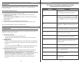
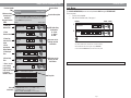
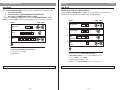
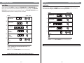
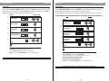
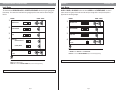
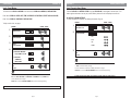
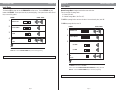
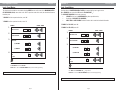
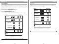
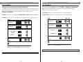
www.sdcsecurity.com
Visit our website for more information on
our complete product line, new product
announcements, pricing, installation
instructions and templates.
M:\INS\INST-E72 Prog. Guide
0701
Introduction
Congratulations, you have just purchased the E72 EntryCheck by SDC, the most advanced stand-alone
door lock and access control system on the market today. The lock, designed for easy installation, will provide years of reliable service when properly installed and maintained.
This manual is designed to act as a guide through the many features and functions of your upgradeable
E72 EntryCheck stand-alone access control system.
Please take the time to read it thoroughly and follow the instructions carefully so that your experience will
be positive and trouble free.
SDC would like to thank you for selecting the E72 EntryCheck for your access control needs.
For Technical Support Contact:
Security Door Controls
3580 Willow Ln.
Westlake Village, CA 91361
Call:
Fax:
E-mail:
1-805-494-0622
1-805-494-8861
[email protected]
For more information about the E72 EntryCheck,
or the complete SDC product line, new product
announcements, pricing and templates, visit our
website at:
www.sdcsecurity.com
Add Group
Table
of Contents
Schedule
Function 03
Before You Begin . . . . . . . . . . . . . . . . . . . . . . . . . . . . . . . . . . . . . . . . . . . . . . . . . . . . . . . . . . . . . . iii
Battery Information . . . . . . . . . . . . . . . . . . . . . . . . . . . . . . . . . . . . . . . . . . . . . . . . . . . . . . . . . . . . iv
Nightly Self Diagnostics . . . . . . . . . . . . . . . . . . . . . . . . . . . . . . . . . . . . . . . . . . . . . . . . . . . . . . . . . iv
Resetting the E72 . . . . . . . . . . . . . . . . . . . . . . . . . . . . . . . . . . . . . . . . . . . . . . . . . . . . . . . . . . . . . . v
Memory Upgrade Information. . . . . . . . . . . . . . . . . . . . . . . . . . . . . . . . . . . . . . . . . . . . . . . . . . . . . . v
Group Security Levels. . . . . . . . . . . . . . . . . . . . . . . . . . . . . . . . . . . . . . . . . . . . . . . . . . . . . . . . . . . vi
Sample Function Programming Page. . . . . . . . . . . . . . . . . . . . . . . . . . . . . . . . . . . . . . . . . . . . . . . . vii
Initialize Lock ID . . . . . . . . . . . . . . . . . . . . . . . . . . . . . . . . . . . . . . . . . . . . . . . . . . . . . . . . . . . . . . . 1
Initialize Great Grand Master. . . . . . . . . . . . . . . . . . . . . . . . . . . . . . . . . . . . . . . . . . . . . . . . . . . . . . 2
Function 12 . . . . . . . . . . . . . . . . . Set Time . . . . . . . . . . . . . . . . . . . . . . . . . . . . . . . . . . . . . . . . . . 3
Function 13 . . . . . . . . . . . . . . . . . Set Date . . . . . . . . . . . . . . . . . . . . . . . . . . . . . . . . . . . . . . . . . . 4
Function 1 . . . . . . . . . . . . . . . . . . User Maintenance . . . . . . . . . . . . . . . . . . . . . . . . . . . . . . . . . . . 5
Function 02 . . . . . . . . . . . . . . . . . Basic Schedule . . . . . . . . . . . . . . . . . . . . . . . . . . . . . . . . . . . . . 6
Function 03 . . . . . . . . . . . . . . . . . Group Schedule . . . . . . . . . . . . . . . . . . . . . . . . . . . . . . . . . . . . . 7
Function 04 . . . . . . . . . . . . . . . . . User Schedule . . . . . . . . . . . . . . . . . . . . . . . . . . . . . . . . . . . . . . 8
Function 05 . . . . . . . . . . . . . . . . . Schedule Passage Mode . . . . . . . . . . . . . . . . . . . . . . . . . . . . . . . 9
Function 06 . . . . . . . . . . . . . . . . . Temporary User Schedule . . . . . . . . . . . . . . . . . . . . . . . . . . . . . 10
Function 07 . . . . . . . . . . . . . . . . . Change Group Association . . . . . . . . . . . . . . . . . . . . . . . . . . . . 11
Function 08 . . . . . . . . . . . . . . . . . Change User PIN . . . . . . . . . . . . . . . . . . . . . . . . . . . . . . . . . . . 12
Function 09 . . . . . . . . . . . . . . . . . Holiday Maintenance . . . . . . . . . . . . . . . . . . . . . . . . . . . . . . . . 13
Function 10 . . . . . . . . . . . . . . . . . Deny/ Restore Access To Selected Groups . . . . . . . . . . . . . . . . . 14
Function 11 . . . . . . . . . . . . . . . . . Set Access Level . . . . . . . . . . . . . . . . . . . . . . . . . . . . . . . . . . . 15
Function 16 . . . . . . . . . . . . . . . . . Clear Memory. . . . . . . . . . . . . . . . . . . . . . . . . . . . . . . . . . . . . . 16
Function 17 . . . . . . . . . . . . . . . . . Battery Status Check . . . . . . . . . . . . . . . . . . . . . . . . . . . . . . . . 17
Function 18 . . . . . . . . . . . . . . . . . Define Open Time. . . . . . . . . . . . . . . . . . . . . . . . . . . . . . . . . . . 18
Function 30 . . . . . . . . . . . . . . . . . Manual Passage Mode . . . . . . . . . . . . . . . . . . . . . . . . . . . . . . . 19
Function 31 . . . . . . . . . . . . . . . . . First Supervisor to Arrive . . . . . . . . . . . . . . . . . . . . . . . . . . . . . 20
Function 32 . . . . . . . . . . . . . . . . . PIN Only Entry . . . . . . . . . . . . . . . . . . . . . . . . . . . . . . . . . . . . . 21
Function 33 . . . . . . . . . . . . . . . . . Double Code Entry . . . . . . . . . . . . . . . . . . . . . . . . . . . . . . . . . . 22
Function 34 . . . . . . . . . . . . . . . . . Lock Audio . . . . . . . . . . . . . . . . . . . . . . . . . . . . . . . . . . . . . . . . 23
Function 36 . . . . . . . . . . . . . . . . . Fail Secure. . . . . . . . . . . . . . . . . . . . . . . . . . . . . . . . . . . . . . . . 24
Function 37 . . . . . . . . . . . . . . . . . Set Alternative Terminator. . . . . . . . . . . . . . . . . . . . . . . . . . . . . 25
Function 14 . . . . . . . . . . . . . . . . . Upload Lock Information . . . . . . . . . . . . . . . . . . . . . . . . . . . . . . 26
Function 15 . . . . . . . . . . . . . . . . . Download Audit Trail. . . . . . . . . . . . . . . . . . . . . . . . . . . . . . . . . 27
Function 20 . . . . . . . . . . . . . . . . . Lock Upgrade . . . . . . . . . . . . . . . . . . . . . . . . . . . . . . . . . . . . . . 28
Function 35 . . . . . . . . . . . . . . . . . IR Interrupt . . . . . . . . . . . . . . . . . . . . . . . . . . . . . . . . . . . . . . . 29
Military Time Conversion Chart . . . . . . . . . . . . . . . . . . . . . . . . . . . . . . . . . . . . . . . . . . . . . . . . . . . 30
Programming Category Maximum Quantities. . . . . . . . . . . . . . . . . . . . . . . . . . . . . . . . . . . . . . . . . . 30
Glossary. . . . . . . . . . . . . . . . . . . . . . . . . . . . . . . . . . . . . . . . . . . . . . . . . . . . . . . . . . . . . . . . . . . . 31
Index . . . . . . . . . . . . . . . . . . . . . . . . . . . . . . . . . . . . . . . . . . . . . . . . . . . . . . . . . . . . . . . . . . . . . . 32
Page i
Page ii
Before You Begin
KEYPAD INFORMATION
The E72 EntryCheck keypad has two special keys: the Terminator and the Programming key.
• Terminator - This key functions like the “enter” key on a computer. Once the terminator is pressed,
the information entered is saved. The default terminator key for the E72 is “*”.
• Programming key - This key is used when entering the programming mode. It is also used by the
GGM for lock initialization. The default programming key is the “#” key.
To program multiple functions into the E72 at one time, at the end of the function instead of selecting the
“*” key, select the “#” key. This will save the last function you entered, and return you to the “enter
function number” area of programming. This will eliminate the repeated entry of your valid code.
USER CODE DEFINITIONS
Creating the GGM Code - When creating the GGM code, this also creates the format for all other user
codes. All users have the same length code, a minimum of 6 and a maximum of 9.
User Identification Number (UID) - a unique number assigned to each user. The UID has the the length of a
minimum of 3, maximum of 4 digits. The UID appears on the audit trail showing user history for that E72.
Group Number - The user address. The Group Number is not entered for access, but used for
management organization purposes. THE GROUP NUMBERS RANGE RANGE 02-99. GROUPS 02-09 ARE
RESERVED FOR MANAGEMENT LEVEL PERSONNEL; SCHEDULING FUNCTIONS CANNOT RESTRICT
THESE USERS. Groups 10-99 are for user groups. These groups should contain users with similar access
rights and times, allowing management to schedule access times by group rather than individual users.
Personal Identification Number (PIN) - a number which can consist of digits, letters and multiple key
depressions, not necessarily unique for each user. (minimum 3 digits, maximum 6 digits.)
Valid User Code - This number is UID and PIN entered into the E72 to gain access, or enter programming
mode. For a user to program a function, they must have a valid user code and correct security level.
Minimum group security level for each function is listed at the top of each page.
Incorrect Valid User Code Entry - If a user incorrectly enters their code 3 times in a row, the lock will go
into a time-out mode for 20 seconds (showing a red LED). If the incorrect code is entered again, the timeout will increase to 40 seconds. This is to deter tampering with the lock.
Incorrect Entry - If an incorrect entry is made during the programming of a function, the lock will respond
with a single beep and a red LED. You must now restart at Step 1, Valid User Code.
Time-out - Once you begin entering information into the E72, if you pause for 5 seconds or more, the lock
will time-out. (Time-out duration 5 seconds.) Previous information entered for that function is deleted
and you will need to begin the process again at Step 1, Valid User Code.
Scheduled Event - An event which has a time or date stamp associated with it.
SCHEDULING FUNCTIONS
The lock is shipped from the factory with the batteries included but not installed. The Date and Time stamps
on the E72 will be incorrect. Before proceeding, enter the correct Time (Func. 12 pg 3) and Date (Func.
13 pg 4).
Battery Information
Batteries
THE E72 IS SHIPPED WITH 4 AA ALKALINE BATTERIES. The life span of the batteries has been tested in
two different ways.
The first test was performed to see how many operations could be performed repeatedly before a failure.
The test averaged 150 thousand operations. The second test was performed over time for normal
operations. This test revealed that the E72 batteries would last approximately four years at 80 - 90
thousand operations. Using the current factory settings, the lockset is set for optimized power usage.
Changing the Batteries
When the batteries need to be changed, you will have 10 minutes to remove the old batteries and install the
four new AA batteries, before memory is effected. IT IS RECOMMENDED TO USE ONLY ALKALINE
BATTERIES, due to the predetermined power settings in the lock. The alkaline battery has a gradual curve
in the drop off voltage. This curve determines the power settings for the two stages of battery warnings and
the Fail Safe settings. A lithium battery differs from an alkaline battery in the life cycle of the battery cell.
A lithium battery has a very sharp drop off voltage, going from fully charged to a dead cell quickly. This
makes monitoring the voltage settings impossible.
Two Stage Low Battery Warning
The E72 has a two-stage low battery warning.
The first warning stage will change the tone and the sound of the audio from a single beep to a double beep
when the user enters their code.
The second warning stage will be a double beep every hour. BATTERIES SHOULD BE CHANGED
IMMEDIATELY. Double beeps will occur until the batteries fail.
To ensure the lock fails in a “locked” mode, use Function 36 Fail Secure or the lock will fail in it’s
last state, either open or closed.
The batteries can also be checked visually using Function 17, Battery Status Check.
The battery status will be displayed on every audit trail as well.
Nightly Self Diagnostics
Nightly Self Diagnostics
The E72 will perform a self-test once a night at 2400 hours. This test will ensure that all components are
fully functioning and operating correctly. This test will only take a few milliseconds and will not be
noticeable to the end users.
If scheduling functions are initiated, ALL USERS MUST HAVE ASSIGNED SCHEDULES TO GAIN ACCESS
EXCEPT MANAGEMENT LEVEL GROUPS 02-09. If no schedules are installed, all users will have access
at all times, provided they have a valid user code. For the maximums for each category see page 30.
Page iii
Page iv
Function 03
Add
Resetting
Group Schedule
the E72
RESETTING THE E72
There may be a time when you need to fully reset your E72 and start over. If you reset the E72, all
previous information in the lock memory will be lost. (This includes: users, scheduling, GGM code,
E72 ID and lock settings.)
Here are the steps to perform a full reset.
1. Remove batteries.
2. Wait approximately 5 minutes to allow capacitor to discharge.
3. If you have a sensor array package, turn the key in the lever and hold it in position while
completing steps 4 and 5.
If you do not have a sensor array package, install a jumper (not included) in the connector with
the yellow and black wires.
4. Insert the batteries.
5. The LED will first turn red. When it changes to green, the lock is reset.
6. Remove the key or jumper (to remove jumper depress yellow and black wire connector catch).
The lock is back to factory default. (Restart by re-initializing the lock.)
E72 Memory Upgrades
E72 MEMORY UPGRADES
Memory upgrades can be purchased from your local SDC distributor or directly from the factory. These
upgrades are permanent and cannot be downgraded, even after a long storage period with no batteries. To
upgrade your E72 memory, there are 3 steps.
1.
2.
3.
Obtain the lock serial number.
The serial number is printed on the exterior backplate of the E72.
Or, using the IDT, the serial number appears on the IDT display, as well as, on the header of the
audit trail (Func. 15).
Obtain upgrade code.
Call SDC at 1-805-494-0622 with your serial number. An SDC customer service representative will
take your order and fax back/call back with your upgrade code. Please retain your upgrade code for
your records.
OR
Call your local SDC distributor with your serial number. They will obtain your upgrade code and fax
back/call back with your upgrade code. Please retain your upgrade code for your records.
Install upgrade number into the E72.
Using Function 20, (Lock Upgrade) enter your upgrade code from the back of your upgrade card.
Note: By upgrading the E72’s memory, the lock will reset to the factory defaults. All
information currently stored in the memory will be lost. It is recommended before updating your
memory, use the IDT to download an audit trail (Func. 15). This will allow you to use the
information later to update the E72’s memory. After the upgrade is complete, the E72 is
re-initialized and the GGM code is created, stored information can be uploaded from the IDT
(Func. 14).
Page v
Group Security Levels
NOTE: GROUPS 02-09 ARE RESERVED FOR MANAGEMENT LEVEL PERSONNEL.
SCHEDULING FUNCTIONS CANNOT RESTRICT THESE USERS.
Group Name
Group No.
Description
Factory Code
FC
None
Factory code “9991234” is the code entered into the lock on
new installations or after full resets. The factory code will act
as the starting point for setting up the lock program.
Great Grand Master
GGM
None
Every lock must contain only one GGM code. The GGM has
the highest level of security authorization. Due to the GGM’s
security level, this code should not be used on an everyday
basis. The GGM user code will set the standard format for all
users.
Grand Master
GM
02
GM is the highest level of security that should be used on an
everyday basis. The GM has full programming rights at all
times.
Master
M
03
Master has programming rights to control user access, but
not functions which effect the security settings of the E72.
Supervisor Group
04
This is the last management group with ability of First
Supervisor To Arrive (Func. 31) access.
Security Guard Group
05
This level allows group members to upload/download audit
and scheduling information to the lock using the IDT.
Emergency Group
06
For Police, Fire Department, Emergency Medical Services etc.
At this level, the group has access at all times, with no
programming ability
Maintenance Group
07
This level is for a group that needs access to the lock at all
times. (Ex. plumber, HVAC etc.) No programming ability.
Service Group
08
This level is for a group that needs access to the lock at all
times. No programming ability.
Open Group
09
This level is for a group that needs access to the lock at all
times. No programming ability.
10-99
These groups have limited access as programmed with no
programming ability.
Users
Page vi
Function 03
Sample FunctionAdd
Programming
Group Schedule
Page
Function Name
Function Number
Function 03
Minimum Group
Security Level
Needed To
Program Function
STEPS
Group Schedule
Level: Master
Function Description
Function schedules OPEN and CLOSE time/day for an established GROUP of
users. This function differs from the Basic Schedule (Func. 02), in that
specific GROUPS can be granted access.
ENTRIES
1. Enter your
UID and PIN.
2. Enter
Function Number.
3. Enter Day
Code from list
below.
4. Enter
appropriate
Group Number.
5. Enter Open
Time.
6. Enter Close
Time.
7. Enter * to exit
or to continue
programming,
enter # and return
to Function
Number. (Step 2)
#
Function Number
0
3
*
Day Code
0
8
See Day Code
Mgmt. Defined
*
Group
1
2
Mgmt. Defined
Open Time
(Military)
Close Time
(Military)
Exit
See Note
Day Code
01-07
08
09
10
11
12
13
07
Hours
17
Hours
Level: Master
The LOCK ID INITIALIZATION process can be implemented ONLY using the FACTORY CODE.
This occurs when:
• The lock is first installed
• After the lock has been reset. (See page v.)
ENTRIES
VISUAL / AUDIO
Valid User Code
Initialize Lock ID
1.
LED /Audio Entry
Confirmation
G= Green
Y= Yellow
R= Red
Grey boxes are for
entering required
information
*
2.
Factory Code
VISUAL / AUDIO
9991234
#
Lock ID
User Defined 6 Digits
Note
The default LOCK IDENTIFICATION NUMBER for this function is 000001.
Use “0” to indicate blanks. (Ex. Room 321=321000 or 000321).
We recommend that each lock be given a unique ID Number.
In order to add the ID Number later, the lock must be fully reset.
*
00
Minutes
*
00
Minutes
White boxes are for
entering variable
information.
IF ERROR ON ENTRY OR NO ENTRY IN 5 SECONDS, LOCK WILL TIME-OUT. BEGIN AT STEP 1.
*
Must be entered as a 2 digit code.
Individual Days (Ex: Monday = 01)
Weekdays - Monday through Friday
Weekends - Saturday & Sunday
Even Weekdays - Tuesday & Thursday
Odd Weekdays - Monday, Wednesday & Friday
Override Pre-Programmed Holidays
All Days
Day Code
Note
Note
Information
#
To DELETE ALL GROUP SCHEDULES, enter “0” in place of the DAY CODE then EXIT “*”.
For MANAGEMENT GROUPS (02-09) Group Schedule CANNOT be employed.
For USER GROUPS (10-99) Group Schedule CAN be employed.
ENTER “#” to RETURN to FUNCTION NUMBER and continue programming.
IF ERROR ON ENTRY OR NO ENTRY IN 5 SECONDS, LOCK WILL TIME-OUT. BEGIN AT STEP 1.
Page vii
Page 1
Initialize Great Grand Master
Function 12
Level: Master
Level: Master
When the Great Grand Master (GGM) is entered it has the two components that are found in all codes.
1.
User ID (UID) 3 to 4 DIGITS
2.
Pin Number (PIN) 3 to 6 DIGITS/ALPHA/MULTIPLE KEY DEPRESSIONS
3.
UID and PIN have a MAXIMUM TOTAL LENGTH of 9 DIGITS.
The length of the GGM’s UID and PIN determine the length of all FUTURE MANAGEMENT and USER
CODES. This allows the GGM to set the overall level of security for the lock at the time of initialization.
TIME MUST BE SET PRIOR TO ACTIVATING SCHEDULING.
This function SETS the INTERNAL TIME of the LOCK. The lock uses military time and is automatically
updated when the upload/download module (IDT) is used. Ex. 1530=3:30 p.m.
ENTRIES
1.
2.
3.
Factory Code
User ID
VISUAL / AUDIO
9991234
*
ENTRIES
1.
2.
#
User Defined (3-4 Digits)
3.
3 to 6 Alpha-Numeric
4.
IF ERROR ON ENTRY OR NO ENTRY IN 5 SECONDS, LOCK WILL TIME-OUT. BEGIN AT STEP 1.
Page 2
#
Function Number
1
2
Time
Exit
See Note
Note
UID MUST be DIGITS ONLY.
PIN CAN be ALPHA/NUMERIC/MULTIPLE KEY DEPRESSIONS.
No group number is given to the GGM.
Only ONE GGM per lock.
VISUAL / AUDIO
Valid User Code
Mgmt. Defined
#
PIN
Set Time
Hours
Minutes
*
*
*
Note
TIME MUST BE SET PRIOR TO ACTIVATING SCHEDULING.
The Default for this function is DAYLIGHT SAVINGS TIME ENABLED.
To DISABLE DAYLIGHT SAVINGS time, press “0” as the LAST DIGIT of the time entry.
Ex. 18380 = DISABLED 1838= ENABLED
For Military Time Conversion Chart, see page 30.
ENTER “#” to return to FUNCTION NUMBER (Step 2) and continue programming.
IF ERROR ON ENTRY OR NO ENTRY IN 5 SECONDS, LOCK WILL TIME-OUT. BEGIN AT STEP 1.
Page 3
Set Date / Format
Function 13
Function 01
User Maintenance
Level: Master
Level: Master
DATE MUST BE SET PRIOR TO ACTIVATING SCHEDULING.
This function SETS the MONTH, DAY, YEAR and DAY OF THE WEEK.
This function creates NEW users or deletes EXISTING users. All USERS are REQUIRED to have a GROUP
NUMBER (See page iii). GGM Code sets standard length format for all USER CODES. (See page iii.)
ENTRIES
ENTRIES
1.
2.
3.
4.
VISUAL / AUDIO
Valid User Code
1.
Enter Date
Exit
See Note
#
Valid User Code
#
2.
Function Number
VISUAL / AUDIO
1
3
Month Day
*
Year
3.
*
*
Note
DATE MUST BE SET PRIOR TO ACTIVATING SCHEDULING.
The DEFAULT for this function is MM/DD/YY.
ALTERNATE DATE FORMAT can be used by entering: DD/MM/YY “0” “*”.
ENTER “#” to return to FUNCTION NUMBER (Step 2) and continue programming.
IF ERROR ON ENTRY OR NO ENTRY IN 5 SECONDS, LOCK WILL TIME-OUT. BEGIN AT STEP 1.
4.
5.
6.
Function Number
User ID
Group Level
PIN
Exit
See Note
0
1
*
Mgmt. Defined (2-4 Digits)
*
*
Mgmt. Defined 02-99 (2 Digits)
*
Mgmt. Defined
*
Note
To DELETE user, enter “0 ” in place of GROUP then EXIT “*”.
GGM CODE sets standard length for all USER CODES. (See page iii.)
ENTER “#” to return to FUNCTION NUMBER (Step 2) and continue programming.
IF ERROR ON ENTRY OR NO ENTRY IN 5 SECONDS, LOCK WILL TIME-OUT. BEGIN AT STEP 1.
Page 4
Page 5
Basic Schedule
Function 02
Function 03
Group Schedule
Level: Master
Level: Master
The BASIC SCHEDULE function is a powerful tool that recognizes those scheduling TIMES that GROUPS
have in COMMON. It was designed to give an overall framework to the lock effectively minimizing
scheduling under other more cumbersome functions. Ex: All groups have access from 8 am to 5 pm daily.
The Basic Schedule is used rather than making separate entries under the group schedule function. The
BASIC SCHEDULE (Func. 02) works in conjunction with PASSAGE SCHEDULE (Func. 05) and HOLIDAY
SCHEDULE (Func. 09).
BASIC SCHEDULE DOES NOT work with GROUP SCHEDULE (Func. 03) or USER SCHEDULE (Func. 04).
Function schedules OPEN and CLOSE time/day for an established GROUP (10-99) of users. This function
differs from the Basic Schedule (Func. 02), in that specific GROUPS can be granted access.
GROUP SCHEDULE DOES NOT work with BASIC SCHEDULE (Func. 02).
ENTRIES
1.
2.
3.
VISUAL / AUDIO
Valid User Code
Function Number
Day Code
Open Time
Close Time
(Military)
6.
2.
#
0
2
*
Exit
See Note
Day Code
01-07
08
09
10
11
13
*
Mgmt. Defined
Hours
Hours
Minutes
Minutes
VISUAL / AUDIO
Valid User Code
#
Function Number
0
3
*
*
Day Code
See Day Code
4.
(Military)
5.
1.
3.
See Day Code
4.
ENTRIES
Mgmt. Defined
*
Group
(Groups 10-99)
5.
*
(Military)
6.
*
*
Must be entered as a 2 digit code.
Individual Days (Ex: Monday = 01)
Weekdays - Monday through Friday
Weekends - Saturday & Sunday
Even Weekdays - Tuesday & Thursday
Odd Weekdays - Monday, Wednesday & Friday
All Days
Note
To DELETE BLANKET SCHEDULE, enter “0” in place of DAY CODE then EXIT “*”.
DATE and TIME must be set BEFORE SCHEDULING.
DAY CODES are 2 DIGITS long.
For Military Time Conversion Chart, see page 30.
ENTER “#” to return to FUNCTION NUMBER (Step 2) and continue programming.
IF ERROR ON ENTRY OR NO ENTRY IN 5 SECONDS, LOCK WILL TIME-OUT. BEGIN AT STEP 1.
Page 6
Hours
Minutes
Hours
Minutes
*
Close Time
(Military)
7.
*
Open Time
Exit
See Note
Day Code
01-07
08
09
10
11
12
13
*
Must be entered as a 2 digit code.
Individual Days (Ex: Monday = 01)
Weekdays - Monday through Friday
Weekends - Saturday & Sunday
Even Weekdays - Tuesday & Thursday
Odd Weekdays - Monday, Wednesday & Friday
Override Pre-Programmed Holidays
All Days
Note
To DELETE ALL GROUP SCHEDULES, enter “0” in place of the DAY CODE then EXIT “*”.
For MANAGEMENT GROUPS (02-09) Group Schedule CANNOT be employed.
For USER GROUPS (10-99) Group Schedule CAN be employed.
For Military Time Conversion Chart, see page 30.
ENTER “#” to return to FUNCTION NUMBER (Step 2) and continue programming.
IF ERROR ON ENTRY OR NO ENTRY IN 5 SECONDS, LOCK WILL TIME-OUT. BEGIN AT STEP 1.
Page 7
User Schedule
Function 04
Function 05
Schedule Passage Mode
Level: Master
Level: Master
Function schedules OPEN and CLOSE time/day for INDIVIDUAL user. This function is intended to work in
conjunction with an existing group schedule. Ex. User “A” belongs to group “25” with access from 8 am-6 pm
Mon.-Fri. User “A” also comes in Sat. The User Schedule function allows User “A” to be part of group “25” and
have additional access on Saturday.
USER SCHEDULE DOES NOT work with BASIC SCHEDULE (Func. 02).
Function SCHEDULES TIMES the lock will enter the PASSAGE MODE and when it will return to restricted
Valid User Code entry. For MANUAL PASSAGE MODE see Func. 30.
ENTRIES
1.
2.
3.
VISUAL / AUDIO
Valid User Code
Function Number
0
4
2.
*
3.
*
Day Code
4.
Mgmt. Defined
*
User ID Number
Open Time
5.
Hours
Minutes
*
6.
Close Time
Exit
See Note
Day Code
01-07
08
09
10
11
12
13
Hours
Minutes
#
0
5
*
*
Day Code
Mgmt. Defined
Open Time
Hours
Minutes
Hours
Minutes
Close Time
Exit
See Note
(Military)
7.
Function Number
(Military)
(Military)
6.
Valid User Code
(Military)
Mgmt. Defined (Up to 4 Digits)
5.
1.
VISUAL / AUDIO
See Day Code
See Day Code
4.
#
ENTRIES
*
*
*
*
*
Must be entered as a 2 digit code.
Individual Days (Ex: Monday = 01)
Weekdays - Monday through Friday
Weekends - Saturday & Sunday
Even Weekdays - Tuesday & Thursday
Odd Weekdays - Monday, Wednesday & Friday
Override Pre-Programmed Holidays
All Days
Note
To DELETE USER GROUP SCHEDULE, enter “0” in place of the DAY CODE then EXIT “*”.
For Military Time Conversion Chart, see page 30.
ENTER “#” to return to FUNCTION NUMBER (Step 2) and continue programming.
IF ERROR ON ENTRY OR NO ENTRY IN 5 SECONDS, LOCK WILL TIME-OUT. BEGIN AT STEP 1.
Page 8
Day Code
01-07
08
09
10
11
12
13
Must be entered as a 2 digit code.
Individual Days (Ex: Monday = 01)
Weekdays - Monday through Friday
Weekends - Saturday & Sunday
Even Weekdays - Tuesday & Thursday
Odd Weekdays - Monday, Wednesday & Friday
Override Pre-Programmed Holidays
All Days
Note
To DELETE SCHEDULE PASSAGE MODE, enter “0” in place of DAY CODE then EXIT “*”.
For Military Time Conversion Chart, see page 30.
ENTER “#” to return to FUNCTION NUMBER (Step 2) and continue programming.
IF ERROR ON ENTRY OR NO ENTRY IN 5 SECONDS, LOCK WILL TIME-OUT. BEGIN AT STEP 1.
Page 9
Temporary User Schedule
Function 06
Function 07
Change Group Association
Level: Master
Level: Master
Function allows an existing USER to be flagged as a TEMPORARY USER. The TEMPORARY USER will
function as a normal user and will have a schedule assigned to them for access rights. The TEMPORARY
USER CODE will become invalid once the date range has expired. The TEMPORARY USER CODES are not
automatically erased, they remain in memory and can be re-activated.
This function allows a USER to be REMOVED from one group and ENROLLED in another existing group.
Once enrolled in the new group, the USER conforms to the new group schedule.
ENTRIES
1.
ENTRIES
1.
2.
3.
VISUAL / AUDIO
#
Valid User Code
Function Number
0
6
2.
3.
*
*
User ID Number
Start Date
Mgmt. Defined
5.
Function Number
User ID
4.
Month Day
*
New Group Number
#
0
7
*
*
5.
Exit
*
*
End Date
Exit
*
Mgmt. Defined
See Note
Mgmt. Defined
6.
Valid User Code
Mgmt. Defined (Up to 4 Digits)
Mgmt. Defined (Up to 4 Digits)
4.
VISUAL / AUDIO
Month Day
*
Note
ALL USERS are REQUIRED to have a GROUP ASSOCIATION.
ENTER “#” to return to FUNCTION NUMBER (Step 2) and continue programming.
See Note
Note
This function is EFFECTIVE from 0000 to 2400 hours of the day access is granted.
To ERASE all TEMPORARY USER FLAGS AND RETURN THEM TO USERS, enter “0”
IN PLACE of UID then EXIT “*”.
ENTER “#” to return to FUNCTION NUMBER (Step 2) and continue programming.
IF ERROR ON ENTRY OR NO ENTRY IN 5 SECONDS, LOCK WILL TIME-OUT. BEGIN AT STEP 1.
IF ERROR ON ENTRY OR NO ENTRY IN 5 SECONDS, LOCK WILL TIME-OUT. BEGIN AT STEP 1.
Page 10
Page 11
Change User PIN
Function 08
Function 09
Holiday Maintenance
Level: User
Level: Master
Function allows the USER to CHANGE their PIN. The change user PIN function adds overall security to the
locks by allowing users to change a compromised PIN at their discretion. Management can prevent PIN
changes by not making the user base aware of this functions existence.
Function DENYS USERS ACCESS on an observed HOLIDAY. The lock views dates between the start date
and the end date as one holiday no matter how many days might actually exist.
Ex.: Start Date 12/24, End Date 12/24= One holiday Start Date 12/24, End Date 12/30= One holiday.
ENTRIES
1.
2.
3.
Valid User Code
#
Function Number
0
8
ENTRIES
*
2.
New PIN Number
User Defined
Verify New PIN Number
User Defined
5.
HOLIDAY SCHEDULING MUST BE MAINTAINED YEARLY. PAST HOLIDAYS DO NOT DELETE AUTOMATICALLY.
1.
See Note
4.
VISUAL / AUDIO
Exit
See Note
*
3.
*
*
Note
If USER makes an ERROR while changing PIN, OLD PIN will still be VALID.
If USER FORGETS their PIN, Management CAN re-enter USER.
Length of Valid User Code = UID and PIN is management defined.
ENTER “#” to return to FUNCTION NUMBER (Step 2) and continue programming.
IF ERROR ON ENTRY OR NO ENTRY IN 5 SECONDS, LOCK WILL TIME-OUT. BEGIN AT STEP 1.
Function Number
0
9
Holiday Start Date
Month Day
Holiday End Date
Mgmt. Defined
5.
#
Valid User Code
Mgmt. Defined
4.
VISUAL / AUDIO
Exit
See Note
Month Day
*
*
*
*
Note
To ERASE all HOLIDAYS, enter “0” in place of holiday START DATE then EXIT “*”.
START and END DATE are the same for a ONE DAY HOLIDAY.
For information on the total number of programmable holidays, see page 30.
HOLIDAY SCHEDULING MUST BE MAINTAINED YEARLY.
PAST HOLIDAYS DO NOT DELETE AUTOMATICALLY.
ENTER “#” to return to FUNCTION NUMBER (Step 2) and continue programming.
IF ERROR ON ENTRY OR NO ENTRY IN 5 SECONDS, LOCK WILL TIME-OUT. BEGIN AT STEP 1.
Page 12
Page 13
Deny/Restore Access To Selected Groups
Function 10
Function 11
Set Access Level
Level: Master
Level: Master
This function allows RESTRICTED ACCESS to SELECTED USER GROUPS without erasing the group/groups
from memory. Once access has been denied to a group/groups then access must be restored using this
function.
ACCESS is DENIED to ALL GROUPS with access levels LOWER than the ENTERED GROUP. In order to
restore access to all groups this function must be used by a manager with a security level equal to or
higher than the restricting manager.
ENTRIES
1.
2.
3.
VISUAL / AUDIO
Valid User Code
Function Number
#
1
0
*
*
Group
ENTRIES
1.
2.
3.
Valid User Code
Function Number
Select One:
(0) Restore Access
(1) Deny Access
5.
Exit
See Note
0
1
*
#
1
1
Group Level
Mgmt. Defined
4.
VISUAL / AUDIO
User Defined
4.
Exit
See Note
*
*
*
*
*
Note
Function DENIES ACCESS to ALL MEMBERS of the selected GROUP.
GGM cannot be denied access.
ENTER “#” to return to FUNCTION NUMBER (Step 2) and continue programming.
Note
The DEFAULT for this function is NO RESTRICTIONS.
To RESTORE access ENTER “99” in the GROUP LEVEL.
ENTER “#” to return to FUNCTION NUMBER (Step 2) and continue programming.
IF ERROR ON ENTRY OR NO ENTRY IN 5 SECONDS, LOCK WILL TIME-OUT. BEGIN AT STEP 1.
IF ERROR ON ENTRY OR NO ENTRY IN 5 SECONDS, LOCK WILL TIME-OUT. BEGIN AT STEP 1.
Page 14
Page 15
Clear Memory
Function 16
Function 17
Battery Status Check
Level: Grand Master
Level: Security Guard Group
This function will CLEAR the MEMORY of the lock and/or CLEAR ALL SCHEDULES, DATE AND TIME.
Function DISPLAYS the BATTERY STATUS using the LED DISPLAY on the keypad as shown below. This
makes regular maintenance as easy as possible. Battery status will also be displayed on audit trail.
Enter "0" to CLEAR ALL USERS, DATE, TIME, SCHEDULES & FUNCTIONS. (EXCEPT GGM and LOCK ID.)
Enter "1" to CLEAR ALL SCHEDULES, DATE AND TIME.
DO NOT USE LITHIUM BATTERIES.
For more information on batteries, see Battery Information (Page iv).
ENTRIES
To fully reset the lock, see page v.
ENTRIES
1.
2.
3.
4.
#
Valid User Code
Function Number
VERIFY
Function Number
1
6
1
6
(0)CLEAR ALL MEMORY
Except GGM & Lock ID
0
Exit
See Note
1
1.
2.
Function Number
1
7
*
FULL
GOOD
LOW
*
*
#
Valid User Code
*
Select One:
(1)CLEAR ALL
SCHEDULES
DATE & TIME
5.
VISUAL / AUDIO
VISUAL / AUDIO
CHANGE
3.
Exit
See Note
*
*
*
Note
DATE and TIME are lost when clearing the memory.
ALL other USER, FUNCTIONS and SCHEDULES are RETURNED to factory DEFAULT “0”.
To fully reset the lock, see page v.
ENTER “#” to return to FUNCTION NUMBER (Step 2) and continue programming.
Note
Lock should be TESTED under NORMAL atmospheric CONDITIONS, as EXTREME HEAT
or COLD will influence battery readings.
For more information on batteries, see Battery Information on page iv.
ENTER “#” to return to FUNCTION NUMBER (Step 2) and continue programming.
IF ERROR ON ENTRY OR NO ENTRY IN 5 SECONDS, LOCK WILL TIME-OUT. BEGIN AT STEP 1.
IF ERROR ON ENTRY OR NO ENTRY IN 5 SECONDS, LOCK WILL TIME-OUT. BEGIN AT STEP 1.
Page 16
Page 17
Define Open Time
Function 18
Function 30
Manual Passage Mode
Level: Master
Level: Master
This function SETS the time the lock will REMAIN OPEN to allow access. The time INTERVAL may vary
between 1-9 SECONDS. Shorter open times help to prevent tailgating. If user opens the door within the set
time, access will be granted.
Manual Passage Mode is designed to allow free access to the door.
There are two types of passage mode:
1. Entered at the door.
2. Schedule Passage Mode. (See Func. 05.)
ENTRIES
1.
VISUAL / AUDIO
#
Valid User Code
To CLOSE the passage function and return the door to its normal security level, enter "0".
To OPEN the passage function, enter "1".
2.
3.
Function Number
Set Time
1
8
*
*
1 to 9 Seconds
4.
Exit
See Note
*
ENTRIES
1.
2.
3.
Valid User Code
IF ERROR ON ENTRY OR NO ENTRY IN 5 SECONDS, LOCK WILL TIME-OUT. BEGIN AT STEP 1.
#
0
*
(0) CLOSE
0
*
(1) OPEN
1
*
Function Number
3
Select One:
Note
The DEFAULT for this function is 3 SECONDS.
ENTER “#” to return to FUNCTION NUMBER (Step 2) and continue programming.
4.
VISUAL / AUDIO
Exit
See Note
*
Note
There is NO additional POWER USAGE while the door is in passage mode.
The DEFAULT for this function is “0” CLOSE.
Function can be used to OVERRIDE SCHEDULED PASSAGE MODE by entering “0” Closed.
ENTER “#” to return to FUNCTION NUMBER (Step 2) and continue programming.
IF ERROR ON ENTRY OR NO ENTRY IN 5 SECONDS, LOCK WILL TIME-OUT. BEGIN AT STEP 1.
Page 18
Page 19
First Supervisor to Arrive
Function 31
Function 32
Pin Only Entry
Level: Grand Master
Level: Grand Master
This function will override the set schedule, denying USERS access until a user with a MINIMUM ACCESS
OF SUPERVISOR (02-04) enters their code. After a supervisor enters their code, the schedule will resume
from that point.
Function allows a SHORTER LENGTH OF CODE to be entered by the user to gain access.
When ENABLED, user enters their PIN number FOLLOWED BY “*”.
To DISABLE the first supervisor function, enter "0".
To ENABLE the first supervisor function, enter "1".
ENTRIES
1.
2.
3.
4.
VISUAL / AUDIO
The POSSIBLE PROBLEMS this function poses are:
•
SECURITY of the lock is COMPROMISED by fewer possible entries;
•
Possibility of DUPLICATE PIN NUMBERS;
•
AUDIT TRAIL is NOT RELIABLE with this function due to restricted retrieval information.
To ENABLE the PIN ONLY, enter "0".
To ENABLE the UID & PIN, enter "1".
#
Valid User Code
ENTRIES
1.
Function Number
3
1
*
2.
Select One:
(0) DISABLE
0
*
(1) ENABLE
1
*
Exit
See Note
3.
Valid User Code
Note
The DEFAULT for this function is “0” DISABLED.
At 0000 HOURS this function RESETS.
ENTER “#” to return to FUNCTION NUMBER (Step 2) and continue programming.
IF ERROR ON ENTRY OR NO ENTRY IN 5 SECONDS, LOCK WILL TIME-OUT. BEGIN AT STEP 1.
#
2
*
(0) PIN ONLY
0
*
(1) UID & PIN
1
*
Function Number
3
Select One:
*
4.
VISUAL / AUDIO
Exit
See Note
*
Note
The DEFAULT for this function is “1” (UID and PIN REQUIRED for entry).
User MUST enter PIN NUMBER and “*” to gain access.
ENTER “#” to return to FUNCTION NUMBER (Step 2) and continue programming.
IF ERROR ON ENTRY OR NO ENTRY IN 5 SECONDS, LOCK WILL TIME-OUT. BEGIN AT STEP 1.
Page 20
Page 21
Double Code Entry
Function 33
Function 34
Lock Audio
Level: Grand Master
Level: Master
The function REQUIRES 2 VALID USER CODES to be entered in order to gain access. For higher security
restrictions, this function can also be set to require one of the codes to be of Management Level. When set
for this option, the first user will enter their code followed by the “*”, the next user will have 5 seconds to
enter their code and the “*” before being timed out.
LOCK AUDIO is designed to give an audio feedback from internal sounding unit. The lock keypad has an
audible click which sounds at all times with every keystroke.
Enter "0" (E72 default) for ONE VALID USER CODE to gain access.
ENTRIES
1.
VISUAL / AUDIO
Valid User Code
#
Enter "1" for TWO VALID USER CODES to gain access.
Enter “2" for TWO VALID USER CODES, ONE MUST BE A MANAGEMENT LEVEL CODE to gain access.
ENTRIES
1.
2.
3.
VISUAL / AUDIO
3
Select One:
(0) SINGLE USER
(1) TWO VALID USERS
(2) MANAGER & USER
4.
Exit
See Note
3.
3
0
1
2
*
*
*
*
*
(0) Audio OFF
0
*
(1) Audio ON
1
*
3
Select One:
*
4.
4
Function Number
#
Valid User Code
Function Number
2.
Exit
See Note
*
Note
The DEFAULT for the LOCK AUDIO function is “0” AUDIO OFF.
ENTER “#” to return to FUNCTION NUMBER (Step 2) and continue programming.
IF ERROR ON ENTRY OR NO ENTRY IN 5 SECONDS, LOCK WILL TIME-OUT. BEGIN AT STEP 1.
Note
The DEFAULT for this function is “0” SINGLE USER.
ENTER “#” to return to FUNCTION NUMBER (Step 2) and continue programming.
IF ERROR ON ENTRY OR NO ENTRY IN 5 SECONDS, LOCK WILL TIME-OUT. BEGIN AT STEP 1.
Page 22
Page 23
Fail Secure
Function 36
Function 37
Set Alternative Terminator
Level: Grand Master
Level: Grand Master
THIS FUNCTION IS ONLY INTENDED FOR USE IN BATTERY POWERED UNITS.
In case the low battery warning goes unnoticed, (See Battery Information page iv) and the lock runs out of
power, this function ensures that the E72 will fail in a secured state. At that time, a key will be required to
open the E72. If this function is not used, the lock will fail in the last state the lock was in.
EGRESS IS ALWAYS PERMITTED.
This function increases the SECURITY of the lock by REVERSING the TERMINATOR and PROGRAMMING
KEYS. This reversal adds another level of complexity to any attempt at hacking codes. (For more
information on the terminators, see page iii.)
TO ENABLE Fail Secure, enter "0". This will set a POWER RESERVE to ENSURE the lock will fail CLOSED.
To ENABLE REVERSE, enter "1" (“#” is the terminator and “*” is the programming key).
To USE DEFAULT, enter "0". (“*” is the terminator and “#” is the programming key)
TO DISABLE Fail Secure, enter "1". This will allow the lock to fail in its last state - either open or closed.
ENTRIES
1.
2.
3.
4.
VISUAL / AUDIO
ENTRIES
1.
#
Valid User Code
2.
Function Number
3
6
*
3.
Select One:
(0) FAIL SECURE
(ENABLED)
0
(1) DISABLE
1
Exit
See Note
*
Note
The DEFAULT for this function is “1” DISABLED.
ENTER “#” to return to FUNCTION NUMBER (Step 2) and continue programming.
4.
#
Valid User Code
7
*
(0) DEFAULT “*”
0
*
(1) REVERSED “#”
1
*
Function Number
3
Select One:
*
*
VISUAL / AUDIO
Exit
See Note
*
Note
The DEFAULT for this function is “0” “*” as terminator.
ENTER “#” to return to FUNCTION NUMBER (Step 2) and continue programming.
IF ERROR ON ENTRY OR NO ENTRY IN 5 SECONDS, LOCK WILL TIME-OUT. BEGIN AT STEP 1.
IF ERROR ON ENTRY OR NO ENTRY IN 5 SECONDS, LOCK WILL TIME-OUT. BEGIN AT STEP 1.
Page 24
Page 25
Upload Lock Information
Function 14
Function 15
Download Audit Trail
Level: Security Guard
Level: Security Guard
This function will take the information stored in the IDT and upload and update the E72’s memory. Any
changes made at the door via the keypad and not updated in the computer will be lost once the update is
complete. For further instruction on the uses of the IDT or software, refer to the IDT instruction manual.
Function will DOWNLOAD the E72 audit trail to the IDT. The number of events downloaded are user defined
but limited to your upgrade option. For the standard E72, the maximum number of downloadable events are
64.
ENTRIES
1.
2.
3.
4.
VISUAL / AUDIO
Valid User Code
After a download, the IDT display will show: battery status, lock ID and serial number.
For the maximum number of downloadable events, see the chart on page 30.
#
ENTRIES
1.
Function Number
1
4
*
2.
Wait For Upload
to be Completed
See Hand
Held Device
3.
Exit
See Note
*
4.
Note
ALL existing SCHEDULE INFORMATION not updated in the computer will be lost upon upload.
IF ERROR ON ENTRY OR NO ENTRY IN 5 SECONDS, LOCK WILL TIME-OUT. BEGIN AT STEP 1.
VISUAL / AUDIO
#
Valid User Code
Function Number
1
5
*
Enter Number of Events
to be Downloaded
Exit
See Note
*
*
Note
Consult page 30 for maximum number of downloadable events.
IF ERROR ON ENTRY OR NO ENTRY IN 5 SECONDS, LOCK WILL TIME-OUT. BEGIN AT STEP 1.
Page 26
Page 27
Lock Upgrade
Function 20
Function 35
IR Interrupt
Level: Master
Level: Grand Master
This function is used to upgrade the memory of your E72. Here are the steps.
This function PREVENTS IR transmission between the lock and the IDT Upload/Download device for extra
security.
1.
2.
3.
Obtain the lock serial number.
The serial number is printed on the exterior backplate of the E72.
Or, using the IDT, the serial number appears on the IDT display, as well as, on the header of the
audit trail (Func. 15).
Obtain upgrade code.
Call SDC at 1-805-494-0622 with your serial number. An SDC customer service representative will
take your order and fax back/call back with your upgrade code. Please retain your upgrade code for
your records.
OR
Call your local SDC distributor with your serial number. They will obtain your upgrade code and fax
back/call back with your upgrade code. Please retain your upgrade code for your records.
Install upgrade number into the E72.
Using this function, enter your upgrade code from the back of your upgrade card.
Note: By upgrading the E72’s memory, the lock will reset to the factory defaults. All
information currently stored in the memory will be lost. It is recommended before updating your
memory, use the IDT to download an audit trail (Func. 15). This will allow you to use the information
later to update the E72’s memory. After the upgrade is complete, the E72 is re-initialized and the
ENTRIES
1.
2.
3.
Enter Upgrade Number
#
2
0
*
*
Manufacturer Supplied
4.
Exit
See Note
To ENABLE the IR Interrupt, enter "1".
ENTRIES
1.
2.
3.
4.
VISUAL / AUDIO
Valid Code
#
5
*
(0) DISABLE
0
*
(1) ENABLE
1
*
Function Number
3
Select One:
VISUAL / AUDIO
Valid User Code
Function Number
To DISABLE the IR Interrupt, enter "0".
Exit
See Note
*
Note
The DEFAULT for this function is “0” DISABLED.
ENTER “#” to return to FUNCTION NUMBER (Step 2) and continue programming.
*
IF ERROR ON ENTRY OR NO ENTRY IN 5 SECONDS, LOCK WILL TIME-OUT. BEGIN AT STEP 1.
Note
UPGRADES are PERMANENT even if lock is reset.
LOCK SERIAL NUMBER REQUIRED.
LOCK CANNOT be DOWNGRADED.
ENTER “#” to return to FUNCTION NUMBER (Step 2) and continue programming.
IF ERROR ON ENTRY OR NO ENTRY IN 5 SECONDS, LOCK WILL TIME-OUT. BEGIN AT STEP 1.
Page 28
Page 29
Glossary
Military Time Conversion Chart
Access code
Numeric or alphanumeric data which when correctly entered into a keypad, allows
authorized entry into a controlled area without causing an alarm condition.
1:00 a.m..................................0100
2:00 a.m..................................0200
3:00 a.m..................................0300
4:00 a.m..................................0400
5:00 a.m..................................0500
6:00 a.m..................................0600
7:00 a.m..................................0700
8:00 a.m..................................0800
9:00 a.m..................................0900
10:00 a.m................................1000
11:00 a.m................................1100
12:00 p.m. Noon .....................1200
Access control
The control of persons, vehicles and materials through entrance and exit of a protected
area utilizing hardware systems specialized procedures to control and monitor the
movement into, out of or within the protected area.
Audit trail
A historical record sequentially accounting for all activities with an access control
system. Such a record allows reconstruction and analysis of events during a given
time period.
Card reader
A device that scans or reads encoded information in or on access control cards.
ESD
Electro Static Discharge
Fail safe lockset
A type of lock set that automatically unlocks when a power failure occurs.
1:00 p.m. ................................1300
2:00 p.m. ................................1400
3:00 p.m. ................................1500
4:00 p.m. ................................1600
5:00 p.m. ................................1700
6:00 p.m. ................................1800
7:00 p.m. ................................1900
8:00 p.m. ................................2000
9:00 p.m. ................................2100
10:00 p.m. ..............................2200
11:00 p.m. ..............................2300
12:00 a.m. Midnight ...............2400
Infrared (IR)
Light waves that are too low frequency to be seen by the unaided human eye.
Keypad
A device for inputting information into a computer controlled system for the purposes
of arming and disarming an alarm system or operating an access control system.
Magnetic card
A type of access control card with a data encoded strip of magnetic material.
Standard Time
Military Time
Programming Category Maximum Quantities*
Category
Valid Users
Audit Trail
Temporary Users
Holidays
Scheduled Events
Denied Groups
E72-64
64
64
32
16
64
96
E72-150
160
832
64
24
96
96
* Further upgrades available, consult factory.
Page 30
E72-300
320
1,600
64
32
160
96
Fail secure lockset A type of lock set that automatically locks when a power failure occurs.
Personal Identification This number can be a combination of digits and letters, increasing the
Number (PIN)
overall number code possibilities.
Proximity card
A radio frequency based card technology that utilizes a microcircuit which when
present to a proximity reader, activates the cards circuitry, thus transmitting the data
stored in the card.
Smart card
An identification card containing an integrated circuit allowing it to receive and store
data, which gives it limited microprocessor intelligence.
Tailgating
In access control, tailgating is the act of one or more individuals entering a controlled
area by using a single card or code. Also known as piggybacking.
User Identification A unique number assigned to each user. The UID has a length 3 to 4 digits. The I.D.
Number (UID)
number will show up in the audit trail showing that user’s history of events for that
lock.
Terminator
The default setting for the lock has the “*” key acting as the terminator which
functions are similar to the “enter” key on a standard computer keyboard.
Programming key The lock default setting has the “# “ key as the programming key, note that the “#” key
is used during the initialization process for the lock GGM.
Valid user code
A valid user code is a users’ UID and PIN number, the user must also have the correct
security level to complete the function desired.
Page 31
Index
Add Group Schedule
Access, Deny/Restore to Selected Groups, Function 10.........14
Access Level, Set, Function 11 ............................................15
Alternative Terminator, Function 37.......................................25
Audio, Lock, Function 34 ......................................................23
Audit Trail, Download, Function 5..........................................27
Basic Schedule, Function 02...................................................6
Battery Information ................................................................iv
Battery Low Power Warning....................................................iv
Battery - Changing.................................................................iv
Battery-Nightly Self Diagnostics ..............................................iv
Battery Status Check , Function 17.......................................17
Date/Format, Set, Function ....................................................4
Deny Access to Selected Groups, Function 10..........................14
Download Audit Trail, Function 15.........................................27
Entry, Double Code, Function 33 ...........................................22
Fail Secure, Function 36 .......................................................24
Factory code ..........................................................................vi
Function 01, User Maintenance ..............................................5
Function 02, Basic Schedule...................................................6
Function 03, Group Schedule ..................................................7
Function 04, User Schedule ....................................................8
Function 05, Schedule Passage Mode.....................................9
Function 06, Temporary User Schedule .................................10
Function 07, Change Group Association................................11
Function 08, Change User PIN ..............................................12
Function 09, Holiday Maintenance........................................13
Function 10, Deny/Restore Access to Selected Groups..........14
Function 11, Set Access Level ..............................................15
Function 12, Set Time.............................................................3
Function 13, Set Date / Format...............................................4
Function 14, Upload Lock Information...................................26
Function 15, Download Audit Trail.........................................27
Function 16, Clear Memory...................................................16
Function 17, Battery Status Check........................................17
Function 18, Define Open Time.............................................18
Function 20, Lock Upgrade ...................................................28
Function 30, Manual Passage Mode .....................................19
Function 31, First Supervisor to Arrive..................................20
Function 32, PIN Only Entry ..................................................21
Function 33, Double Code Entry............................................22
Function 34, Lock Audio .......................................................23
Function 35, IR Interrupt.......................................................29
Function 36, Fail Secure .......................................................24
Function 03
Function 37, Set Alternative Terminator ................................25
GGM Code..............................................................................iii
Group Association, Change, Function 07...............................11
Group Numbers......................................................................iii
Group Security Levels ............................................................vi
Group Schedule, Function 03 ..................................................7
Holiday Maintenance, Function 09........................................13
Initialize Lock ID, ...................................................................1
Initialize Great Grand Master ..................................................2
IR Interrupt, Function 35.......................................................29
Keypad Information................................................................iii
Manual Passage Mode, Function 30 .....................................19
Memory Upgrades...................................................................v
Memory, Clear, Function 16 ..................................................16
Open Time, Define, Function 18............................................18
Passage Mode, Manual, Function 30 ....................................19
PIN Number ...........................................................................iii
PIN,Change User, Function 08 ..............................................12
PIN Only Entry, Function 32 ..................................................21
Programming key ...................................................................iii
Resetting the E72....................................................................v
Restore Access to Selected Groups, Function 10 ..................14
Sample Function Programming Page .....................................vii
Scheduled Events ..................................................................iii
Scheduling .............................................................................iii
Schedule Passage Mode, Function 05.....................................9
Schedule (Basic), Function 02 ................................................6
Schedule (Group), Function 03 ...............................................7
Schedule (User), Function 04 .................................................8
Supervisor To Arrive, First, Function 31.................................20
Temporary User Schedule, Function 06 ................................10
Terminator..............................................................................iii
Terminator, Alternative, Function 37......................................25
Time, Define Open, Function 18............................................18
Time, Set, Function 12............................................................3
Upgrade, Lock.......................................................................28
Upload Lock Information, Function 14...................................26
User Identification Code (UID)................................................iii
User PIN, Change, Function 08 .............................................12
User Schedule, Function 04 ....................................................8
User Maintenance, Function 01 .............................................5
Valid User Code......................................................................iii
User Code Definitions.............................................................iii
Page 32