1
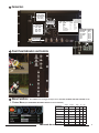
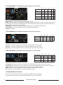
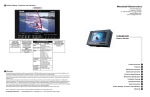
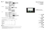
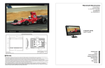
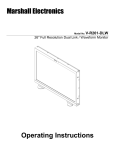
11
Standard Accessories
Accessories Supplied with the V-R151P-4A
•
•
•
•
12
Users manual
“Brick” type 12vdc power supply with 4 Pin Female XLR connector
“V” Mount battery adapter
VESA 75 Mount
Marshall Electronics
1910 East Maple Ave.
El Segundo, CA 90245
Tel.: 800-800-6608 • 310-333-0606
Fax: 310-333-0688
www.LCDRacks.com
Email: [email protected]
Optional Accessories
Desk Stand - VP-LCD171H-ST-01 - Use for Desk Top
V-R151P-4A Users Guide
13
Warranty
Marshall Electronics warranties to the first consumer, that this V-R151P-4A 15 inch LCD rack mounted monitor will, under normal use, be free from defects in workmanship and materials, when
received in its original container, for a period of one year from the purchase date.
This warranty is extended to the purchasing end user only and proof of purchase is necessary to honor the warranty. If there is no proof of purchase provided with a warranty claim, Marshall
Electronics reserves the right not to honor the warranty set forth above. Therefore, labor and parts may be charged to you.
This warranty does not apply to product exterior and cosmetics. Misuse, abnormal service or handling, improper alterations or modifications in design or construction, voids this warranty. No
sales personnel of the seller, nor any other person is authorized to make any warranties other than those described above, or to extend the duration of any warranties on behalf of Marshall
Electronics, beyond the time period described above.
An extra note about LCD displays: It is considered normal for a minimal amount of pixels, not to exceed three, to fail on the periphery of the display active viewing area. Marshall Electronics
has the option to reserve service for display pixel failure if deemed unobtrusive to effective use of the monitor by our technicians.
Due to constant effort to improve products and product features, specifications may change without notice.
Product Overview
Features
Specifications
Setup
Connectors
Front Panel Indicators and Controls
Menu Functions
PC Formats Supported from VGA and DVI Connectors
Video Formats Supported By Component and DVI Inputs
Video Formats Supported By Composite and S-Video Inputs
Standard Accessories
Optional Accessories
Warranty
1
2
3
4
5
6
7
8
9
10
11
12
13
Product Overview
1
The V-R151P-4A is a rack-mounted monitor with a 15”, 4:3 aspect ratio active matrix LCD/TFT module. Mounting can also be achieved via
a VESA 75 reinforced mount point on the rear of the unit or with the included rack ears. The display will produce a high-resolution 1280W x
1024H SXGA image from a computer with Analog RGBHV outputs plus DVI-Digital or display scaled video images. Component, Composite
Video or Y/C (S-video) images are displayed via a proprietary internal scaling LSI The unit is designed to fit into an EIA standard 19” rack and
occupies 6RU of space. For ease of operation the V-R171P-4A includes front mounted selector buttons for menu operations with On Screen
Menu Display (OSD) and “ON AIR” tally. A U.L. Class 2 power supply is included and the unit is factory ready for rack mount installation.
Features
2
•
•
•
•
•
•
•
•
•
•
XGA Resolution 1280 × 1024 pixels, 3.93 million total RGB pixels produce 16.7 million colors
300 candela per meter2 luminance
Compact design fits in EIA standard rack 8U high
VESA 75 mount for wall, ceiling or desk top
Automatic Gamma Correction
16:9 or 4:3 aspects
Self-powered tally system for 4 Video Inputs
NTSC/PAL Factory Configuration
1500 CRT viewing angles
12 VDC 4-pin XLR power connector with external power supply
3
Specifications
8
Display (Viewing Area)
15” Diagonal
Resolution (Pixels)
1024H × 768V
Screen Format
4x3
PC Formats supported from VGA and DVI connectors
Resolution
H Frequency ( kHz )
V Frequency ( Hz )
640x480
31.469
59.94
Pixel Frequency ( MHz )
640x480
35.000
66.667
30.24
640x480
34.940
69.884
28.513
640x480
37.861
72.809
29.765
640x480
37.500
75.0
31.5
720x400
31.469
70.087
28.322
25.175
Screen Treatment
Anti-Glare and Anti-scratch Hard Coat
Dot Pitch
0.264 square pixel
Pixel Response
13ms Maximum - Black to White to Black (3.5ms rise, 9.5 ms decay)
Viewing Angle
80° (D) From Center
Brightness (in cd/m²)
300 cd/m²
800x600
35.156
56.25
36.0
Color Temp
D-65
800x600
37.879
60.317
40.0
Color Gamut
SMPTE/EBU
800x600
43.764
70.02
45.513
Backlight
CCFL 50,000 hour
800x600
48.077
72.188
50.0
Contrast Ratio
500:1
800x600
46.875
75.0
49.5
Video Inputs System
NTSC or PAL Factory Configured
1024x768
48.780
60.001
64.11
TV Tuner System
NTSC
1024x768
48.363
60.004
65.0
1024x768
56.476
70.069
75.0
1024x768
57.703
72.039
78.476
1024x768
60.030
75.029
78.75
1280x720
47.760
60.0
74.481
Inputs
YPrPb Component (3 BNC), Composite Video (4BNC)
S-Video (Y/C) (4 Pin Mini Din female), sXGA 15Pin HD-15 Female
DVI 27 (Pin DVI-I Female), Tally (HD-15 Female)
Rack Mount Dimensions
19.12”W × 10.5”H × 2.5”D (48.5cm x 26.7cm x 6.35cm)
Desk Top Dimensions
17”W x 13”H x 2.5”D (40.6cm x 35cm x 6.35cm)
1280x768
47.700
60.0
80.136
Approx. Weight
13 lbs (5.9kg)
1280x768
60.150
75.0
102.977
Power Consumption
70Watt Max 12 VDC from included power supply (V-PS12-5V1(XLR))
Operating Temperature
0°C to 50° C (Storage -20°C to +60°C)
Compliance
FCC-Class A, ANSI-63.4 (Certificates on file)
RoHS WEEE/Environmental
Do not dispose. Return to Manufacturer or Authorized Recycle Facility
4
Setup
1. Unpack the V-R151P-4A and accompanying power supply.
Physically inspect for any damage that may have occurred during shipping. Should there be any damage, immediately
contact Marshall Electronics at 800-800-6608. If you are not located within the continental united states call +1 310-333-0606.
2. Install in your desired location.
3. Connect required cables for signal input and output.
4. Attach connection from power supply to the back of the unit.
5. Plug the power supply into the A.C. source
6. Turn on the V-R151P-4A by depressing the power switch located on the front of the unit.
7. Perform input selections and screen adjustments as detailed in following sections of this document
2
9
V-R151P-4A Users Guide
10
Video Formats Supported By Component and DVI Inputs
720x480 Interlaced
15.735
60/59.94
13.500
720x576 Interlace
15.735
50.0
13.595
480 Progressive
60
27
720 Progressive
60
74.25
1080 Interlace
60
74.25
Video Formats Supported By Composite and S-Video Inputs
720x480 Interlaced
15.735
59.94
13.500
720x576 Interlaced
15.735
50.0
13.595
Marshall Electronics
5
5
Connectors
12 VDC from
power supply
4 Pin Male XLR
Pin 4 - Pos
Pin 1- Neg
VGA/XGA Connector
VESA 75mm
Attach Points
PIN#
1
2
3
4
5
6
7
8
S-Video IN
4 Pin Din (Female)
Pin1 - GND
Pin2 - GND
Pin3 – Y in
Pin4 – C in
SIGNAL
RED
GREEN
BLUE
NC
GND
RED SHIELD
GREEN SHIELD
BLUE SHIELD
PIN#
9
10
11
12
13
14
15
SIGNAL
NC
NC
NC
NC
HSYNC
VSYNC
NC
4 Composite
Video Inputs
6
Front Panel Indicators and Controls
7
Menu Functions
Tally IN HD-15 Female
Pin1- Green
Pin2- Red
Pin3-Amber
Pin4 Gnd Pin5Pin6Pin7-
Pin8Pin 9Pin10Pin11Pin12Pin13Pin14Pin15-
Note: MENU select will toggle through 5 menus, PICTURE, SCREEN, FUNCTION, SOURCE and TV
1. Picture Menu (Use UP/DOWN/LEFT/RIGHT buttons to select function)
YPrPb
Brightness
Contrast
Sharpness
Tint
9
9
9
9
S-Video
9
9
9
9
Video
9
9
9
9
Color temp
Marshall Electronics
DVI
9 9
9 9
9 9
Phase
Color
PC
9
9
9
9 9
3
2. Function Menu (Use UP/DOWN/LEFT/RIGHT buttons to select function)
YPrPb
S-Video
Video
PC
DVI
9
9
9
9
9
9
9
9
9
9
9
9
9
9
Auto Configure
DPMS
9
9
9
Reset
OSD Time Out
Sleep Timer
Language
AUTO Configure – Used for PC signals to auto fit image to screen.
DPMS – When selected to ON, the Digital Power Management System will place the monitor into standby when there is no
input signal for 12 seconds and will automatically turn on the monitor when a signal is applied to the last selected source.
Reset – Restores the monitor to factory settings
OSD TIME-OUT – Set time in seconds (0 to 60) for OSD to drop from screen after last button push
SLEEP TIMER – Used to automatically turn monitor off after programmed delay
Language – Not Used
3. Screen Menu (Use UP/ DOWN/ LEFT/ RIGHT buttons to select function)
YPrPb
S-Video
Video
PC
DVI
9 9
9 9
9 9
H-Position
V-Position
Frequency
V-Position – Use LEFT and RIGHT buttons to adjust horizontal position of the PC Image
H-Position – Use LEFT and RIGHT buttons to adjust wertical position of the PC Image
Frequency – Use LEFT and RIGHT buttons to adjust the pixel clock width of the PC Image
4. Source Menu (Use UP/ DOWN/ LEFT/ RIGHT buttons to select function)
Analog RBG (PC)
Composite Video
S-VHS Video
YPrPb
YPrPb
S-Video
Video
PC
DVI
9
9
9
9
9
9
9
9
9
9
9
9
9
9
9
9
9
9
9
9
Analog RGB – Select the on screen source display to be from the HD-15 PC connector on the rear of the unit.
Composite Video – Select the on screen source display to be from the 4 BNC(Video) connectors on the rear of the unit.
S-VHS Video – Select the on screen source display to be from the 4 Pin S-Video Connector
YPrPb – Select the on screen display to be from the component 3 BNC YPrPb connectors
DVI – Select the on screen display to be from the DVI Digital Connector
5. Alternate Menu Functions
Menu is shown by holding down ALT and then pressing the MENU button. (ALT+MENU).
Function selection and cursor movement is performed with the source selection buttons.
4
V-R151P-4A Users Guide