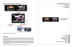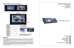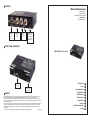
1
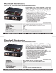
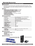
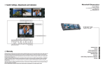
8
Connectors
Marshall Electronics
1910 East Maple Ave.
El Segundo, CA 90245
Tel.: 800-800-6608 • Fax: 310-333-0688
www.LCDRacks.com
Email: [email protected]
S-Video
&
YCrCb
inputs
9
Composite
BNC
input
SDI
Output
1+2
6VDC from
V-PS6-1.2A
Power Supply
Left Pin-Pos
Right Pin-Neg
Switch Settings and Indicators
BC-0103-10 Users Guide
Product Overview
Selection
Switch
Features
Power Signal
Lock Indicator
10
Warranty
Marshall Electronics warranties to the first consumer, that this BC-0103-10 analog to digital Converter will, under normal use, be free from
defects in workmanship and materials, when received in its original container, for a period of one year from the purchase date.
This warranty is extended to the first consumer only and proof of purchase is necessary to honor the warranty. If there is no proof of purchase provided with a warranty claim, Marshall Electronics reserves the right, not to honor the warranty set forth above. Therefore, labor and
parts may be charged to you.
This warranty does not apply to product exterior and cosmetics. Misuse, abnormal service or handling, improper alterations or modifications
in design or construction, voids this warranty. No sales personnel of the seller, nor any other person is authorized to make any warranties
other than those described above, or to extend the duration of any warranties on behalf of Marshall Electronics, beyond the time period
described above.
Due to constant effort to improve products and product features, specifications may change without notice.
Ver. 2009-0401
Electrical Specifications
General Information
Included Accessories
Optional Accessories
Operational Setup
Connectors
Switch Settings and`Indicators
Warranty
1
2
3
4
5
6
7
8
9
10
1
76
Product Overview
The BC-0103-10 is a Composite Video or Y/C (S-Video) (NTSC/PAL) to Serial Digital Interface (SDI) conversion module. Featuring automatic cable compensation, 12-bit processing and a superior adaptive comb filter, the Bc-0103-10 is an ideal solution
for critical DTV applications and facility transitions to a digital environment. There is also a built in Color Bar Generator, System
indicator (PAL/NTSC), and dipswitch settings for Pedestal (On/Off), Adaptive Comb Filter (On/Off), Input signal AGC (On/Off)
and White Peak. All Marshall Electronics Processing and Distribution modules include power supply and owners manual.
An optional base holder (V-CB1) is available for use in desktop applications plus two options for 19” rack mounting (V-CRM2
and V-CRM-3).
2
Optional Accessories
A.
A. 2 Module Rack Mount Kit (Model V-CRM2)
B. 3 Module Rack Mount Kit (Model V-CRM3)
B.
Features
• Cost effective solution for DTV and Multimedia Applications
• Converts Composite Video or Y/C to Digital Component (SDI)
Desktop Stand (Model V-CB1)
• NTSC or PAL operation with automatic detection
• Illuminated power and input signal indicators
• Adaptive filtering removes NTSC interlace artifacts
• 2 x over sampling for true color reproduction
• 12 Bit analog to digital conversion
• 10-bit qauntization of output signal
• 1 line process delay
• Includes color bar generator
• Includes Power Supply Model V-PS6-1.2A
7
3
4
Electrical Specifications
Signal Input
BNC for Composite Video 75Ω, 4 pin mini-din Y/C Video
Signal Output
2 BNC SDI 10 bit Component Digital (SMPTE-259M/ITU-R BT601)
Sample Frequency
27mhz
K factor
<1%
Signal to Noise
>63 db
Differential gain/phase
0.4% / 0.60
Input Cable length
Up to 1000ft (300m) AGC compensated - (Belden 8281 typical)
Power required
6 V D.C. from external power supply (included) max 1.2 AMP
General Information
Power required
6V D.C. from external supply 3.0 Amp max
Dimensions
4.75”W x 3.75”D x 1.0”H
Weight
0.55 lbs
Operational Setup
1. Unpack the BC-0103-10 and accompanying V-PS6-1.2A power supply. Physically inspect for any damage that may have
occurred during shipping. Also verify there is a small package with mounting accessories. Should there be any damage,
immediately contact Marshall Electronics at 800-800-6608. If you are not located within the continental united states call +1
310-333-0606.
2. Install in your desired location. If wall mounting is required, attach the mounting brackets by removing the Phillips head
screws on the sides, closest to the rear of the unit. (See Below) Only one screw per side should be removed.
Use the same screw to attach the bracket with the flange facing away from the side and parallel to the front of the BC-0103-10
metal case. The flange has two holes. For desktop use, apply the supplied rubber pads.
3. Connect required cables for signal input and output.
Please note that power must be applied to the BC-0103-10 for the SDI Output to be activated. All BNC connectors should be
rated for 75Ω.
3. Plug the V-PS6-1.2A power supply into the A.C. source
4. Attach twist lock power connection from V-PS6-1.2A power supply to the back of the unit.
5. Turn on the BC-0103-10 by depressing the power switch located on the front of the unit.
Refer to Page 4 picture for location of switch settings.
Bracket Installation
5
2
Included Accessories
Power Supply (Class 2)
Desktop Stand (Model V-CB1)
Users Guide
3 Module Rack Mount Kit (Model V-CRM3)
Weight
Wall Mount Brackets
BC-0103-10 Users Guide
Feet Installation
Marshall Electronics
3